
Subscribe to Our Youtube Channel
Related Manuals for Armstrong HumidiClean HC-6000 Series


Summary of Contents for Armstrong HumidiClean HC-6000 Series
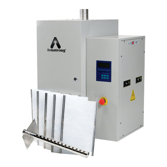
- Page 1 HumidiClean Humidifiers ™ Series HC- 6100/6300/6500/6700 Installation, Operation and Maintenance Instructions Please read and save these instructions 539D-EN V2.0...
-
Page 2: Table Of Contents
Contents Warning Labels ........3-4 Model Number Description ..... 5 Installation ........6-13 Display Menus ........14-15 Start-Up Procedure and Operation .... 16 Maintenance ........17-21 Troubleshooting ........21-26 Typical Wiring Schematic ....... 27-36 Repair Parts ........37-41 PID Control ........42 Software Update ........ -
Page 3: Warning Labels
The Armstrong HumidiClean™ humidifier converts ordinary tap water or purified water to steam for distribution to raise the relative humidity level. To allow HumidiClean™ to function to its full capability, be certain to install in accordance with Armstrong recommendations. DANGER: ELECTRICAL SHOCK HAZARD HIGH VOLTAGES EXIST INSIDE THE HUMIDIFIER TO PROTECT YOURSELF AND OTHERS FROM ACCIDENTAL SHOCKS: 1. - Page 4 Warning: Do not operate the supplied humidifier in combustible or explosive surroundings. Warning: Do not operate the supplied humidifier if there is any damage to the cabinet or any components in humidifier are damaged. Warning: The main switch should be a connection breaker which has over current and leakage current protecting functions per code EN60947-3 or EN60947-2 if point gap required by EN60947-3 can be fulfilled.
-
Page 5: Model Number Description
C = Rated voltage of unit is 400V/380V Pre-Installation 1. Check Shipment. A claim should be filed with the transportation company, (and reported to Armstrong), if any items are missing or damaged. 2. Check Local Codes. The installation of HumidiClean™ should be in accordance with all applicable building, plumbing, and electrical codes. -
Page 6: Installation
Installation Figure 6-1 HC-6100/6300 Installation Pitch Min. 1” Per 12” Back to Unit Hose Clamp Steam Hose or Copper Full Size Tee See Detail “A” Hose 2” Insulated Copper 2” Copper Tee “P” Trap Drain Every Soldered Joints 20’ of Piping or at Reducer Bottom of Vertical Run 1/2”... - Page 7 HC-6100/6300 Mounting The HumidiClean™ models HC-6100/6300 are designed to be wall mounted. A wall mounting bracket and lag screws are provided for mounting on 410 mm (16”) centers. The operating weight of the unit is 106 kg (233 lbs). A clearance of 600 mm (23”) on the front and sides of the cabinet is required for servicing. 1.
- Page 8 Table 8-1. Recommended Branch Circuits Rating Amp 1-12 13-15 16-20 21-24 25-32 33-40 41-48 49-64 68-80 81-100 101-120 121-140 141-60 (AWG) Wire (mm2) Circuit Breaker Table 8-2. Steam Capacities and Rating Amperages HC6100/HC6100DI HC6300/HC6300DI 3 KW Unit 9 KW Unit 15 KW Unit 18 KW Unit 30 KW Unit...
- Page 9 Duct Steam Distribution 1. The dispersion tube should be proper length. Verify correct size from Table 9-1. 2. Install dispersion tube(s) horizontally in duct so holes face upward. Air flow must be vertical up or horizontal. Do not restrict duct with a height of 200 mm (8”) or less. Installations over 10 m/s (1800 FPM) air velocity are not recommended.
- Page 10 When shielded cable is used, shield is to be grounded at the humidifier only. The wire should not be longer than 30 meters (100 ft). If the wire is out of this limit, please contact Armstrong. Refer to Figures 11-1 and 11-2 for wiring schematics.
- Page 11 Figure 11-1 Standard Humidistat Supply Main Stat/Sensor In Modulating High Limit Sensor Outdoor D51768 or Temperature Sensor D51772 Ground 0-10 Vdc Stat Class 2 Alarm A8581 High Limit/ High Limit Air Flow Switch Humidistat Ground A9023 Pressure Switch To Set Up: 1) S3 - 24 VAC (Top Position) 2) S2-1, 2, 3, 4, 5 Off 3) Select 0-10v “Signal”...
- Page 12 Figure 12-1 0-10 Vdc or 4-20mA Control Signal Supply Main Stat/Sensor In Modulating Control High Limit Sensor Signal Outdoor Temperature Sensor Ground S5079a,b,c 4-20ma Setup or 10 vdc Setup 1) S2-1, 2, 3 On if 4-20ma 2) S2 Off (All) If 0-10vdc 3) Select Corresponding Signal Type In Setup Menu.
- Page 13 High Limit Humidistat Remove the jumper tab from ground and in of high limit/pressure switch connections and wire the high limit stat between these terminals. Refer to Figure11-1 (the overall wiring diagram) for more information. A duct mounted high limit humidistat is recommended to prevent over-saturation of the duct air. Use an on-off controller that opens on fault (high humidity).
-
Page 14: Display Menus
Display Menus Designs, materials, weights and performance ratings are approximate and subject to change without notice. Visit armstronginternational.com for up-to-date information. - Page 15 Designs, materials, weights and performance ratings are approximate and subject to change without notice. Visit armstronginternational.com for up-to-date information.
-
Page 16: Start-Up Procedure And Operation
When power is initially supplied to the unit from the circuit breaker, the LCD will display “ARMSTRONG HC6000”. The “POWER” LED will come on and the unit’s fill valve solenoid is energized to allow water to enter the tank at a rate of 1.2 L/min (.31 GPM) (HC-6500/6700 fill rate is 3.735 L/min (1 GPM)). -
Page 17: Maintenance
Maintenance When 90% of the setting service time has accumulated, the “STATE” LED on the control panel will blink in yellow. (Refer to EOL settings, for bed life duration settings). If the HumidiClean™ is not serviced at this time; the unit will continue to operate for the remaining 10% of the service life setting. - Page 18 End of Season Drain If at any time during normal operation there is not a demand for a continuous 72 hour period, HumidiClean drains the tank and the PC Board initiates a drying cycle by cycling the heating elements for short intervals in order to dry the ionic beds.
- Page 19 Figure 19-1 HC-6100/6300 Figure 19-2 HC-6500/6700 Designs, materials, weights and performance ratings are approximate and subject to change without notice. Visit armstronginternational.com for up-to-date information.
- Page 20 Cleaning the Water Level Electrodes 1. If there is water in the steam generating tank, operate the “SETUP”, “MODE” menu to “MANUAL DRAIN”. The drain valve should energize, and the unit should completely drain. 2. After the tank has drained, turn off the main power at the disconnect. 3.
-
Page 21: Troubleshooting
OFF and the component disconnected from wiring. All continuity checks should be made with main power OFF. If unsure concerning any of the following procedures, PLEASE consult the Armstrong Humidification Group at (269) 273-1415. Humidifier will not fill with water when power is applied. - Page 22 Humidifier fills with water, but does not show steam output for 3 minutes after reaching low water level. 1. Perform steps 1 through 3 from above “Humidifier will not fill...” 2. For Tap Water: Check AC voltage across the common electrode (longest) and the low level electrode (medium length).
- Page 23 Humidifier overfills with water on initial fill.. 1. Check electrode canister (float canister for DI units) and level electrodes for debris or scale build up. Clean as needed. See Page 20 for cleaning procedure for electrodes. On DI Units, the high water float switch may be defective or “hung up”.
- Page 24 Humidifier runs continuously, %RH is well under set-point. 1. Verify humidistat/RH sensor is wired correctly and dip switches (S2 & S3, See Fig. 11-1 and 12-1) on the PC board are set correctly for the humidistat signal. 2. Check humidistat demand signal at low voltage terminal strip. It should be close or at 100%. 3.
- Page 25 Dispersion tube spits water or water is present in duct Hint: It is very helpful to cut a small observation window in the duct and cover it with Plexiglas so the steam discharge from the manifold can be observed. This way the problem can be narrowed down to piping/steam quality (steps 1 and 2) or a condensation problem (steps 3 and 4).
- Page 26 Diagnostics There are some diagnostic routines programmed into the PC board. If these routines detect a problem the unit will shut down and display the error message on LCD, the “STATE” LED will be on in red. 1. INIT: FILL TIME - - The low level switch has not closed after 45 minutes of fill valve on time. This is only on initial start-up or after a complete drain down.
-
Page 27: Typical Wiring Schematic
Typical Wiring Schematic HC6100-Wye Wiring Layout (380V, 400V, 480V, 600V) Designs, materials, weights and performance ratings are approximate and subject to change without notice. Visit armstronginternational.com for up-to-date information. - Page 28 HC6100-Delta Three Phase Wiring Layout (208V, 220V, 240V) Designs, materials, weights and performance ratings are approximate and subject to change without notice. Visit armstronginternational.com for up-to-date information.
- Page 29 HC6100-PAR Single Phase Delta Wiring Layout (208V, 220V, 240V) Designs, materials, weights and performance ratings are approximate and subject to change without notice. Visit armstronginternational.com for up-to-date information.
- Page 30 HC6300-Wye Wiring Layout (380V, 400V, 480V, 600V) Designs, materials, weights and performance ratings are approximate and subject to change without notice. Visit armstronginternational.com for up-to-date information.
- Page 31 HC6300-Delta Wiring Layout (208V, 220V, 240V) Designs, materials, weights and performance ratings are approximate and subject to change without notice. Visit armstronginternational.com for up-to-date information.
- Page 32 HC6500-Wye Wiring Layout (380V, 400V, 480V, 600V) Designs, materials, weights and performance ratings are approximate and subject to change without notice. Visit armstronginternational.com for up-to-date information.
- Page 33 HC6500-Delta Wiring Layout (208V, 220V, 240V) Designs, materials, weights and performance ratings are approximate and subject to change without notice. Visit armstronginternational.com for up-to-date information.
- Page 34 HC6500-WYE (2 contactors) Wiring Layout (380V, 400V, 480V, 600V) Designs, materials, weights and performance ratings are approximate and subject to Designs, materials, weights and performance ratings are approximate and subject to change without notice. Visit armstronginternational.com for up-to-date information. change without notice. Visit armstronginternational.com for up-to-date information.
- Page 35 HC6500-Delta (2 contactors) Wiring Layout (208V, 220V, 240V) Designs, materials, weights and performance ratings are approximate and subject to change without notice. Visit armstronginternational.com for up-to-date information.
- Page 36 HC6700-WYE Wiring Layout (380V, 400V, 480V, 600V) Designs, materials, weights and performance ratings are approximate and subject to change without notice. Visit armstronginternational.com for up-to-date information.
-
Page 37: Repair Parts
Repair Parts HC6100/6300 Repair Parts Item Item Electrical Compartment Electrical Compartment Item Item Water Compartment Water Compartment Part No. Part No. Part No. Part No. and Front Panel and Front Panel PVC Tubing 5/8” PVC Tubing 5/8” A7618A A7618A Label Front Panel With Keypad Label Front Panel With Keypad D10876 D10876... - Page 38 Heating Elements 6100/6300 TC= Thermocouple HC-6100 3kW DI Voltage Without TC With TC Without TC With TC 2PCS/Unit 1PCS/Unit 2PCS/Unit 1PCS/Unit B5808-1 B5809-1 B5810-1 B5811-1 B5808-2 B5809-2 B5810-2 B5811-2 B5808-1 B5809-1 B5810-1 B5811-1 B5808-3 B5809-3 B5810-3 B5811-3 B5808-4 B5809-4 B5810-4 B5811-4 HC-6100 15kW...
- Page 39 HC6500/6700 Repair Parts Item Electrical Compartment Item Water Compartment Part No. Part No. and Front Panel Item Electrical Compartment Item PVC Tubing 5/8” A7618A Label Front Panel With Keypad D10876 Water Compartment Part No. Part No. and Front Panel Emergency Stop Button D10866 Clap Hose Flat .63 Olive B2716-11...
- Page 40 Heating Elements 6500/6700 TC= Thermocouple HC6500/HC6700 30kW 33.5kW 40kW 45kW Voltage Without TC With TC Without TC With TC Without TC With TC Without TC With TC 5PCS/Unit 1PCS/Unit 5PCS/Unit 1PCS/Unit 5PCS/Unit 1PCS/Unit 8PCS/Unit 1PCS/Unit B5433-1 B5434-1 B5433-1 B5434-1 B5433-1 B5434-1 B5433-1 B5434-1...
- Page 41 Resistance Values of Components Resistance Value of 6100/6300 Components Resistance Value of 6500/6700 Components Component Voltage Resistance Component Voltage Resistance Fill Valve 24Vac 18Ω Fill Valve 24Vac 8.8Ω Drain Valve 24Vac 10Ω Drain Valve 24Vac 4.1Ω Contractor 24Vac 7-9Ω Thermocouple in Heating Elements 0.51Ω...
-
Page 42: Pid Control
PID Control PID control is essential on the HumidiClean™ series for maintaining the desired relative humidity (RH) by adjusting the humidifiers output. Please note that the PID control is only used when a RH sensor is supplying the demand in place of a humidistat (configured in Operation Setup Menu). -
Page 43: Software Update
Software Update Procedure of HC6000 PCB-1 R1.2/1.3 Board Soft Refresh Install the driver program for Atmel MCU, SAM-BA on your computer first. The link for the latest version of the Atmel program can be found here: www.armstronginternational.com/hc6000refresh • Before refreshing the code, the old code in CPU must be erased: 1. - Page 44 7. Click “Connect” button to enter the download window. Please see Figure 44-1. Fig. 44-1 Code Download Window 8. Click the “open folder” button on the right of textbox “Send File Name” to open the latest code, please see Figure 44-2. You will then have to locate the .bin file that you downloaded from the website and then hit open.
- Page 45 9. Click the button “Send File” to send the latest code into board. You will be asked to unlock the involved lock regions (0 to 6), click the button “Yes” to begin send code into board. Please see Figure 45-1. Fig.
-
Page 46: Communication
Communication Modbus Protocol Setup 1) Wire to the RS-485 port, following Figure 46-1. 2) Make sure that all proper connections are made and that the installation instructions that start on page 6 have been adhered to. Power unit on. 3) Once unit is on go to “Setup” and verify the following data: a. - Page 47 BACnet™ Protocol Setup 1. Attach protocessor into upper right hand corner of main pc board. a. BACnet™ MSTP - The ethernet connection should be going to the inside of the board. b. BACnet™ IP - The ethernet connection goes to the outside of the board. Make sure that all pins are seated properly and making a good connection.
- Page 48 BACnet™ – BACbeat by Polarsoft LonWorks™ - Echelon LonMaker. Instructions on how to download and use this software to connect with the Armstrong humidifier can be found on www.armstronginternational.com. Designs, materials, weights and performance ratings are approximate and subject to...
- Page 49 Table 49-1.BACnet Variant List ™ BACnet ™ Address Description Value / (Unit) Attribute data type Fill valve status 0:off 1:on Drain valve status 0:off 1:on Binary contactor 1 status 0:off 1:on read only Input contactor 2 status 0:off 1:on contactor 3 status 0:off 1:on contactor 4 status 0:off 1:on...
- Page 50 Table 50-1.Modbus Variant List Data Address Description Value / (unit) Function Number Class 10001 Fill valve status 0:off 1:on 10002 Drain valve status 0:off 1:on 10003 contactor 1 status 0:off 1:on function 2, read only 10004 contactor 2 status 0:off 1:on 10005 contactor 3 status 0:off 1:on...
- Page 51 Table 51-1.Modbus Variant List, continued Data Address Description Value / (unit) Function Number Class 40001 Language Select 0:English 1:Chinese 40002 Set RH / Demand 40003 Duct High Limit set point 40004 Outside temp. high set point (°C) 40005 Outside temp. low set point 40006 Outside RH low set point 40007...
- Page 52 Dip Switch Settings for Protocessor Profile PSP to BACnet IP/BACnet MSTP HC6000 PSP to Metasys N2 HC6000 Modbus RTU to BACnet IP/BACnet MSTP HC6000 Modbus RTU to Metasys N2 HC6000 Modbus RTU to BACnet IP/BACnet MSTP HC6000 Legacy Modbus RTU to Metasys N2 HC6000 Legacy Address Designs, materials, weights and performance ratings are approximate and subject to change without notice.
- Page 53 Dip Switch Settings - Continued Profile PSP to BACnet IP/BACnet MSTP HC6000 PSP to Metasys N2 HC6000 Modbus RTU to BACnet IP/BACnet MSTP HC6000 Modbus RTU to Metasys N2 HC6000 Modbus RTU to BACnet IP/BACnet MSTP HC6000 Legacy Modbus RTU to Metasys N2 HC6000 Legacy Address Designs, materials, weights and performance ratings are approximate and subject to change without notice.
- Page 54 Dip Switch Settings - Continued Profile PSP to BACnet IP/BACnet MSTP HC6000 PSP to Metasys N2 HC6000 Modbus RTU to BACnet IP/BACnet MSTP HC6000 Modbus RTU to Metasys N2 HC6000 Modbus RTU to BACnet IP/BACnet MSTP HC6000 Legacy Modbus RTU to Metasys N2 HC6000 Legacy Address Designs, materials, weights and performance ratings are approximate and subject to change without notice.
- Page 55 Dip Switch Settings - Continued Profile PSP to BACnet IP/BACnet MSTP HC6000 PSP to Metasys N2 HC6000 Modbus RTU to BACnet IP/BACnet MSTP HC6000 Modbus RTU to Metasys N2 HC6000 Modbus RTU to BACnet IP/BACnet MSTP HC6000 Legacy Modbus RTU to Metasys N2 HC6000 Legacy Address Designs, materials, weights and performance ratings are approximate and subject to change without notice.
-
Page 56: Dimensional Data
Dimensional Data 1” Drain Electrical Supply Knock-Out for Humidistat Knock-Out for Humidistat Figure 56-1. Models HC-6100 and HC-6300 Table 56-1. Physical Data HC-6500, HC-6700 HC-6100 and HC-6300 and HC-6700DI Inches Inches “A”-Width 21-15/16 “B”-Height 32-1/16 56-3/18 1428 “C”-Depth 22-1/3 32-3/32 “D”-Drain - Back 29-3/16 “E”-Drain - Side... - Page 57 Figure 57-1. Models HC-6500 and HC-6700 — Front, Side, Top Views Designs, materials, weights and performance ratings are approximate and subject to change without notice. Visit armstronginternational.com for up-to-date information.
-
Page 58: Start-Up Checklist
Start-Up Checklist Armstrong HC6000 Series Pre Start-Up Checklist Humidifier model: ______________ Serial #: _______________ Voltage: __________ ph: ______ KW : __________ Steam Capacity: ____________ lbs/hr. Job name: ________________________________ Unit Tag: _______________ Inspected by: _________________________ Date: _____/_____/______ Water Type: r Tap water... - Page 59 Steam Dispersion Type: r Humidipack™ r Expresspack r Fan package (EHF) r Dispersion Tube r Dispersion Tube with Drain r Other ____________________________________________ Plumbing: Inlet Water: r Inlet water pressure between 25-120 psig Drain Lines: Size: ________ r Air gap located within 3’ of humidifier r Line pitched 1”...
-
Page 60: Start-Up Procedure
Start-Up Procedure Armstrong HC6000 Series Start Up Checklist Humidifier model: _______________________ Serial # : _________________ Voltage: _____________ ph: _________ KW : _____________ Steam Capacity: _________________ lbs/hr. Unit Tag:___________________ Job name: _____________________________________________________ Unit Tag: _______________ r Completed Start up Checklist If checklist was not completed, complete before proceeding with start up. - Page 61 Notes Designs, materials, weights and performance ratings are approximate and subject to change without notice. Visit armstronginternational.com for up-to-date information.
- Page 62 Notes Designs, materials, weights and performance ratings are approximate and subject to change without notice. Visit armstronginternational.com for up-to-date information.
-
Page 63: Warranty
Armstrong’s repair or replacement of the part or product, excluding any labor or any other cost to remove or install said part or product, or at Armstrong’s option, to repayment of the purchase price. As a condition of enforcing any rights or remedies relating to Armstrong products, notice... - Page 64 Designs, materials, weights and performance ratings are approximate and subject to change without notice. Visit armstronginternational.com for up-to-date information. Armstrong International North America • Latin America • India • Europe / Middle East / Africa • China • Pacific Rim armstronginternational.com 539D-EN V2.0 © Armstrong International, Inc.
Need help?
Do you have a question about the HumidiClean HC-6000 Series and is the answer not in the manual?
Questions and answers