
Related Manuals for Armstrong Gas Fired HumidiClean Series


Summary of Contents for Armstrong Gas Fired HumidiClean Series
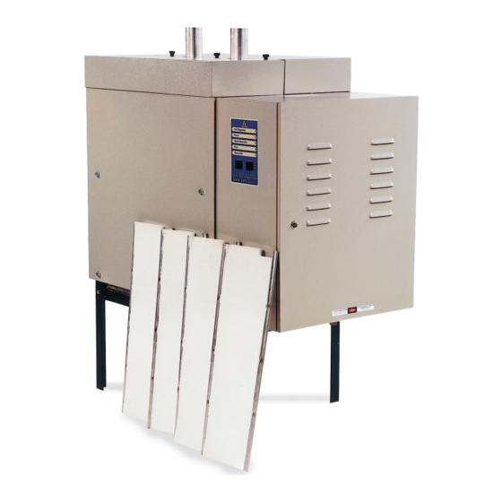
- Page 1 Armstrong Series GFH Gas Fired HumidiClean™ (GFH-150, GFH-300 and GFH-450) Category I / III Gas Fired Appliance Installation and Maintenance Manual Please read and save these instructions 548-EN...
- Page 2 This guide is to be left with the equipment owner. For Customer Support Call: (269) 273-1415 Armstrong International, Inc. 816 Maple Street Three Rivers, MI 49093 Designs, materials, weights and performance ratings are approximate and subject to change without notice. Visit armstronginternational.com for up-to-date information.
-
Page 3: Table Of Contents
Table of Contents Safety Precautions ........................4 Installation ..........................5 Site Selecton ........................5 Mounting Unit ........................6 Water Fill Supply ......................8 Electrical Service ......................8 Drainage ........................... 8 Gas Piping ..........................8 Gas Leak Testing ......................9 Combustion Air ........................... 10 Venting (General) ........................ -
Page 4: Safety Precautions
Safety Precautions Warning: Improper installation, adjustment, alteration, service, maintenance, or use can cause carbon monoxide poisoning, an explosion, fire, electrical shock, or other conditions that may cause personal injury or property damage. Consult a qualified installer, service agency, local gas supplier, or your distributor or branch for information or assistance. -
Page 5: Installation
Installation Check Shipment. A claim should be filed with the transportation company, and reported to Armstrong International, Inc. if any items are missing or damaged. Important: Remove all shipping materials before installing the humidifier Humidifier flue gasses must be vented to the outside atmosphere. -
Page 6: Mounting Unit
Mounting Unit The Series GFH is designed to be floor mounted on a level surface. Required Clearance For recommended service and maintenance purposes, the following clearances should be maintained: Front: 40” Left Side: 1" Figure 6-1. Model 150 ... - Page 7 Table 7-1. GFH Gas Fired HumidiClean Physical Data GHF-150 GFH-300 GFH-450 A - Tank Width 35-1/4 48-1/2 1232 B - Overall Height 54-3/16 1378 54-3/16 1376 54-3/16 1376 C - Overall Width 46-1/8 1172 50-3/8 1280 54-7/8 1394 D - Steam Outlet to End of Cabinet 24-13/16 23-13/16 24-13/16...
-
Page 8: Water Fill Supply
Water Fill Supply The humidifier can use any potable or purified water supply. Water pressure must be 25 – 125 psi (1.7 – 8.6 bar). Water temperature must be less than 140°F (60°C). Average fill rates for all models is 3gpm (0.19 l/sec). -
Page 9: Gas Leak Testing
Gas Supply Line Plugged 1/8" NPT Test Gauge Conn. Humidifier Cabinet Gas Cock Gas Cock Supplied by Ground Joint Armstrong International, Inc. Union Note: All piping and fittings external to humidifier supplied by others. 3" Min. Drip Pocket Table 9-1. Gas Pipe Capacities Gas Flow in Piping (Cu. -
Page 10: Combustion Air
Combustion Air Caution: Air for combustion must not be contaminated by halogenated hydrocarbons, which include fluoride, chloride, bromides and iodide. These elements are found in aerosol sprays, detergents, bleaches, cleaning solvents, salts, air fresheners, and other household products. Humidifier warranty is voided when failure of gas equipment is due to operation in a corrosive atmosphere. - Page 11 The outdoor air source can be a connection outside the building or a connection to an outdoor air plenum inside the building. If the inlet combustion air is to be drawn in from a connection outside the building, special precautions must be made, such as proper termination outside the wall, and a screen on the air inlet to prevent any debris from entering the air inlet pipe.
-
Page 12: Venting (General)
Venting Overview - This humidifier is a Category I / III appliance, which means it produces a positive pressure in the vent system when it is exhausting the appliance flue products to the outdoors. It may be vented vertical or horizontal but special flue pipe must be used which is listed for Category I / III appliances for horizontal piping. -
Page 13: Horizontally Vented
If this humidifier is vented to a lined masonry chimney, the chimney must be sized and installed in accordance with the provisions of the National Fuel Gas Code, or Canadian CAN/CGA.B149 requirements. Vent connectors from the humidifier to the chimney should be made with a vent pipe rated for Category I/III appliance rating. -
Page 14: Vertically Vented
Fig. 5-1 for “P” trap detail. Alternative for shortened non-wettable vapor trail For applications with particularly limited downstream absorption distance, Armstrong HumidiPack may be considered. HumidiPack is a prefabricated separator/header and multiple dispersion tube assembly. It provides uniform distribution and shortened non-wetting vapor trail. Consult Armstrong Installation Bulletin No. -
Page 15: Control Wiring
Table 21-1 for correct switch setting. Ground Refer to Figures 15-1 and 15-2 for appropriate wiring. Sail / Inter. A8581 High Limit Ground 4. Wire standard Armstrong 0-10 Vdc humidistat as shown in Humidistat A9023 Fan Interlock or Figure 15-1. Pressure Switch Figure 15-2 Armstrong C-1471 &... -
Page 16: Air Flow Pressure Switch
High Limit Humidistat A duct mounted High Limit Stat (Armstrong Part A8581) is recommended as a precaution against localized saturation in the duct. It is an on-off controller that opens the contact on a rise in humidity (opens on fault). -
Page 17: Outdoor Enclosure Option
(see drawings on pages 18-21). Consult local codes for exact flue height requirements. B-Vent type piping will be acceptable for all the outdoor enclosure units. An optional curb package can be provided with the unit. Please consult factory, or your local Armstrong Sales Representative for more information. - Page 18 Gas Fired Roof Installation Designs, materials, weights and performance ratings are approximate and subject to change without notice. Visit armstronginternational.com for up-to-date information. North America • Latin America • India • Europe / Middle East / Africa • China • Pacific Rim armstronginternational.com...
- Page 19 GFHE 150 Outdoor Enclosure Designs, materials, weights and performance ratings are approximate and subject to change without notice. Visit armstronginternational.com for up-to-date information. North America • Latin America • India • Europe / Middle East / Africa • China • Pacific Rim armstronginternational.com...
- Page 20 GFHE 300 Outdoor Enclosure Designs, materials, weights and performance ratings are approximate and subject to change without notice. Visit armstronginternational.com for up-to-date information. North America • Latin America • India • Europe / Middle East / Africa • China • Pacific Rim armstronginternational.com...
- Page 21 GFHE 450 Outdoor Enclosure Designs, materials, weights and performance ratings are approximate and subject to change without notice. Visit armstronginternational.com for up-to-date information. North America • Latin America • India • Europe / Middle East / Africa • China • Pacific Rim armstronginternational.com...
-
Page 22: Start-Up Procedure
Start Up Procedure Only qualified personnel should perform start up procedure. Examine the electrical compartment for any loose or disconnected Figure 22-1 component wiring. Check to make sure all of the control wiring has been completed and been done correctly. Unit Diagnostic Remove the top cover of the unit by unscrewing the screws holding the lid in Power... -
Page 23: Principal Of Operation
Principal of Operation The Gas Fired HumidiClean humidifier converts ordinary tap water or purified water to steam for distribution to raise the relative humidity level. The demand for humidity is sensed by a humidistat, which sends a control signal to the Gas Fired HumidiClean. When power is initially supplied to the unit from the circuit breaker, all LEDs will illuminate for 5 seconds. -
Page 24: Maintenance
When servicing or replacing components, use only Armstrong approved replacement parts. Please contact Armstrong directly, or your local Armstrong Representative for a complete parts list. Any substitution of parts or controls not approved by Armstrong International, Inc. is at the owner’s risk. -
Page 25: Cleaning Level Control Electrodes
8. Armstrong also offers a non-caustic cleaning solution called Rite-Quick. Please contact Armstrong, or your local Armstrong Representative for more information. 9. Install new ionic beds, snapping them into place on the support pins. 10. Be sure lid gasket is lapped over all edges of tank access opening. Replace and secure lid. -
Page 26: Burner Assembly
8. Reinstall the probes and probe wires in their proper locations. The high water probe (shortest) goes in the right hole of the canister. The low water probe (medium length) goes in the left front hole of the canister. The common probe (longest) goes in the left, rear hole of the canister. 9. -
Page 27: Removing / Replacing Heat Exchanger
Removing / Replacing Heat Exchanger Turn the Steam Generation switch to the off position to drain the tank completely. Tun off gas, electricity and water supply to the unit. Using a vacuum, remove all dust from the control cabinet area, and blower assembly. Disconnect the gas piping going to the gas valve. -
Page 28: Troubleshooting
Troubleshooting Diagnostics There are some diagnostic routines programmed into the PC board. If these routines detect a problem the unit will shut down and flash the “ERROR” LED a certain number of times, followed by a long pause. Table 28-1 Service Power Steam Generator... -
Page 29: Clearing Error Codes
Clearing Error Codes After troubleshooting, the error state must be cleared by depressing the reset button for 10 seconds. All the LED's will then flash. Release the reset button and the unit should resume normal operation (it will fill or drain to get to the low level switch then fill to the high and begin boiling). -
Page 30: Wiring Schematics
Wiring Schematics 115V System Ladder Schematic Designs, materials, weights and performance ratings are approximate and subject to change without notice. Visit armstronginternational.com for up-to-date information. North America • Latin America • India • Europe / Middle East / Africa • China • Pacific Rim armstronginternational.com... - Page 31 Outdoor Enclosure Units System Wiring Schematic Designs, materials, weights and performance ratings are approximate and subject to change without notice. Visit armstronginternational.com for up-to-date information. North America • Latin America • India • Europe / Middle East / Africa • China • Pacific Rim armstronginternational.com...
- Page 32 System Wiring Schematic Designs, materials, weights and performance ratings are approximate and subject to change without notice. Visit armstronginternational.com for up-to-date information. North America • Latin America • India • Europe / Middle East / Africa • China • Pacific Rim armstronginternational.com...
- Page 33 System Wiring Schematic Designs, materials, weights and performance ratings are approximate and subject to change without notice. Visit armstronginternational.com for up-to-date information. North America • Latin America • India • Europe / Middle East / Africa • China • Pacific Rim armstronginternational.com...
- Page 34 Designs, materials, weights and performance ratings are approximate and subject to change without notice. Visit armstronginternational.com for up-to-date information. North America • Latin America • India • Europe / Middle East / Africa • China • Pacific Rim armstronginternational.com...
-
Page 35: Parts List
Parts List GFH Series Gas Fired HumidiClean Item Number Part Number Description A21583 Drain Valve A21582 Fill Valve C4559 Liquid Level Canister B5139 Float Switch - DI B5135 Bracket, Liquid Level B2960 Low Level Safety Probe C5389 PC Board w/Stand-Offs B5140 LED Board B6624... - Page 36 As a condition of enforcing any rights or remedies relating to Armstrong products, notice of any warranty or other claim relating to the products must be given in writing to Armstrong: (i) within 30 days of last day of the applicable warranty period, or (ii) within 30 days of the date of the manifestation of the condition or occurrence giving rise to the claim, whichever is earlier.
Need help?
Do you have a question about the Gas Fired HumidiClean Series and is the answer not in the manual?
Questions and answers