Advertisement
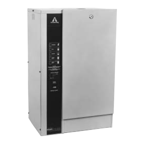
Armstrong EHU-600 Series Humidifiers
The Armstrong EHU-600 Series humidifier is an electronically controlled,
non-pressurized, electric steam-generating humidifier, with its vapor discharged into a
duct of an air-handling system or through a fan package.
To allow the EHU-600 Series humidifier to function to its full capability, be certain to
install in accordance with Armstrong recommendations.
These installation and maintenance guidelines should be used by experienced person-
nel as a guide to ensure that the Armstrong EHU Humidifier functions correctly. Selection
or installation of equipment should always be accompanied by competent technical
assistance. We encourage you to contact your local representative or Armstrong if further
information is required.
READ AND SAVE THESE INSTRUCTIONS
HUMIDIFICATION
Installation and Maintenance of
Bulletin No. 526-G
Advertisement
Table of Contents

Subscribe to Our Youtube Channel
Related Manuals for Armstrong EHU-600


Summary of Contents for Armstrong EHU-600
- Page 1 To allow the EHU-600 Series humidifier to function to its full capability, be certain to install in accordance with Armstrong recommendations.
-
Page 2: Table Of Contents
F. Diagnostics • • • • • • • • • • • • • • • • • • • • • • • • • • Page 29 1. Output circuits 2. Input circuits G. Humidistat Troubleshooting • • • • • • • • • • • • • • Page 31 © Armstrong International, Inc. 2003... -
Page 3: Check Shipment
Pre-Installation 1. Check Shipment A claim should be filed with the transportation company (and reported to Armstrong) if any items are missing or damaged. Your shipment may consist of as many as four cartons which contain: a. Humidifier b. Steam generator(s) (two cartons on Model EHU-602) c. -
Page 4: Mounting The Humidifier
Installation 1. Mounting The Humidifier The EHU-600 Series is intended to be mounted on a wall by means of 3/8" diameter lag screws or other suitable fasteners capable of supporting the maximum operating weight of the humidifier. Mounting Bracket Model EHU-600: Making sure the humidifier is level, hold it against the 3/8”... -
Page 5: Water Fill Supply
50 and 800 micromhos have been used successfully. Please consult factory if micromhos are over 800. If unsure of water conductivity, Armstrong will test free of charge. Consult factory. e. Connect the water supply to the 3/8" tube compression fitting on the fill valve adapter. - Page 6 Figure 6-1: Steam Generator Tank Consult factory. Connections Model EHU-600: Steam generator drain and cabinet drain are the same, Steam Generator Tank 1" O.D. A short piece of 1" I.D. clear hose is provided. Models EHU-601 and 602: Steam generator drain is 3/4" NPT. Cabinet Be Sure Feet Set drain is 5/8"...
-
Page 7: Drain Connection
Installation and Maintenance EHU-600 Series Humidifiers Preferably the location should be 6 inches down stream and/or 10 feet Steam Dispersion Tube upstream from any dampers, vanes, bends in the duct, or controllers 1-3/8" O.D. (1-1/4" Nom.) Copper Tube (i.e. high limit stat). Do not install the dispersion tube into ducts in which... -
Page 8: Steam Generator
C-1472 Figure 8-4: On/Off Humidistat Figure 8-5: Armstrong Humidistat 7. Control Humidistat The Series EHU-600 is compatible with any humidistat with the follow- Figure 8-6: ing characteristics: Pressure Loss in Copper Pipe NOTE: Use of shielded wire or wiring in conduit is recommended for (40 Feet Equivalent Run) control wiring. - Page 9 Installation and Maintenance EHU-600 Series Humidifiers The EHU-600 as shipped, is usually set to accept input signals from the Armstrong control humidistat. To adapt the EHU-600 to a different Capacity Stepping Selector type of control humidistat (with characteristics as listed above) jumper Display Connector BJ2 must be changed on the printed circuit board (See Fig.
- Page 10 100%. 8. High Limit Duct Humidistat Figure 10-2: Control Range for A duct mounted High Limit Stat (Armstrong Part A8581) is recommended Sensing Elements as a precaution against localized saturation in the duct. It is an on-off controller that opens the contact on a rise in humidity (opens on fault).
-
Page 11: Steam Dispersion Tube
Complete installation and wiring instructions are contained in the duct pressure switch package. Armstrong Pressure Switch: (Armstrong Part A9023) All Pressure and electrical connections and set point adjustments are on side for each installation. Temperature limit: 32°F. to 180°F. - Page 12 Installation and Maintenance EHU-600 Series Humidifiers 10. Wiring Diagram Figure 12-1: EHU-600 Wiring Diagram...
-
Page 13: Physical Data
Installation and Maintenance EHU-600 Series Humidifiers 11. Capacity Chart Chart 13-1: EHU-600 Series Capacities and Nominal Amperage Ratings Output lb./hr. (kg/hr.) @ Voltage Recommended Branch Circuit Single Phase Three Phase Rating Module Wire Fuse Model EHU-600 Humidifiers (One Steam Generator) 2.1(.9) - Page 14 "S" Right Clearance * Water Supply Conn. 3/8" Compression. Unit is designed to mount on 16" centers. 2 lag screws are provided for EHU-600. 2 lag screws & bracket are provided for EHU-601 & 602. 1Z\x" I.D. Hose Cuff 3/4" NPT...
- Page 15 The Armstrong EHU-600 Series consists of three models: The EHU-600, 601 and 602. The maximum capacity of the series is 192 lb/hr.
- Page 16 The EHU-600 Series has a patented self-regulating maximum output feature that eliminates manual adjustment and improves humidity control. In low demand situations, units with greater capacity can quickly overshoot setpoint because a fraction of the output satisfies the requirement.
-
Page 17: Control Humidistat
Installation and Maintenance EHU-600 Series Humidifiers 2. Suggested Specification Steam humidifier for distribution of humidity (steam vapor) into air handling system or directly into space shall be of the self-contained, electronically controlled design. a. Humidifier shall generate steam from ordinary tap water. - Page 18 "Demand Meter" – Indicates the demand for humidity in relation to the RH set on the humidistat. The demand meter for the EHU-600 is a series of 5 LED's which indicate demands of 10%-30%, 30%-50%, 50%-70%, 70%-90%, and 90%-100%.
- Page 19 Armstrong humidistat. See troubleshooting section of this manual for more information on humidistat wiring. NOTE: If the humidistat is not the standard Armstrong stat, the method of forcing a demand signal will be different. Generally, increasing the humidity set point on the humidistat will generate a demand signal.
- Page 20 Installation and Maintenance EHU-600 Series Humidifiers Another method of forcing a 100% demand is to remove the controller input signal from terminal 6, jumper terminal 13 to terminal 6 with a short piece of wire, and select either 1.9-3.9Vdc or on/off control setting on the main circuit board.
- Page 21 Tube 21. If the dispersion tube is equipped with a drain fitting, verify that it is working. Look at the tube mounting plate, there is an Armstrong "A" Logo or "UP" sticker which should be pointing up. If not, the tube will not drain properly (See Figure 21-1).
- Page 22 Installation and Maintenance EHU-600 Series Humidifiers 1. Recommended Maintenance Schedule Maintenance 1 Week after start up a. Check unit operation b. Look in drain pan for leaks. c. Check steam piping for leaks. d. Observe duct low points for signs of poor humidity distri- bution.
- Page 23 This is a bottom blowdown, so if minerals stick to the sides of the steam generator, they will accumulate. The standard drain interval is every 30 minutes for the EHU-600 and every 15 minutes for the EHU-601/602. Drain duration is automatically adjusted based on water hardness. If the water is very hard an increased drainage EPROM may be needed.
- Page 24 Installation and Maintenance EHU-600 Series Humidifiers c. Softening: Water softeners remove calcium and add sodium which stays in solution instead of plating out. Minerals will drain out and accumulate less. Caution: Soft water may be more conductive and does not allow a protective coating to form on electrodes.
- Page 25 Installation and Maintenance EHU-600 Series Humidifiers Note: Arcing or flashing in the steam generator tank can be caused by one or more of the following: 1. Poor drainage 2. Abnormal water conditions 3. Dirty tank (needs cleaning) If you notice arcing, shut the unit off and call the factory before restarting unit.
- Page 26 • Check the drain valve, tank drain adapter and tubing for proper operation and good flow when the tank is drained prior to removal. • On EHU-600 models, it is easier to disconnect the electrical wires back at the contactor, not on top of the steam generator tank.
- Page 27 When reinstalling push pin connector, make sure they are tight. See Figure 6-3 and 6-4. Washer Hexnut Model EHU-600 – Three Phase a. Clean the inside of the steam generator thoroughly and rinse with clear water. O-Ring b. High voltage units are supplied with a barrier/drain screen assembly in the lower tank half to reduce the possibility of arcing and increase electrode life.
- Page 28 Tighten these so they are snug. Figure 28-2: Model EHU-600 1 Phase Model EHU-600 is shown above. Models EHU-601 and EHU-602 are similar but some part numbers are different. Parts Description 11. Hose Nut Gasket 21. Upper Tank Half - 1 Phase 1.
-
Page 29: High Limit Duct Humidistat
Installation and Maintenance EHU-600 Series Humidifiers Diagnostics The EHU-600 has a diagnostic function which serves as a trouble- shooting aid. The diagnostics will check all the output circuits: fill valve, drain valve, contactor, and display lights to make sure they are working. -
Page 30: Operation
If All the lights are on, then all controls are allowing the humidifier to fill. In case of component malfunction, consult your Armstrong Represen- tative or the factory for further assistance. Note: To end the diagnostic routine, push and release the Tank On/ Off switch once. -
Page 31: Troubleshooting
Installation and Maintenance EHU-600 Series Humidifiers If the Armstrong Humidistat is mis-wired Table 31-1 shows the unit Humidistat response. * indicates wrong wire connected. W, G, and B stand for Troubleshooting white, green, and black, the wire colors on the humidistat. See Section 7 for more information on control humidistat wiring. - Page 32 As a condition of enforcing any rights or remedies relating to Armstrong products, notice of any warranty or other claim relating to the products must be given in writing to Armstrong: (i) within 30 days of last day of the applicable warranty period, or (ii) within 30 days of the date of the manifestation of the condition or occurrence giving rise to the claim, whichever is earlier.
Need help?
Do you have a question about the EHU-600 and is the answer not in the manual?
Questions and answers