
Subscribe to Our Youtube Channel
Related Manuals for Armstrong EvaPack Series


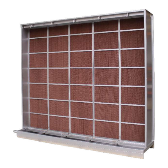
Summary of Contents for Armstrong EvaPack Series
- Page 1 EvaPack™ Series IOM-542-V11 Evaporative Pad Adiabatic Humidifier/Cooler Installation and Operation Manual For RW and DW configuration...
-
Page 2: Table Of Contents
Table of Contents General Safety Information ..........................3 Product Information ..............................5 EvaPack ™ humidifier, operation principle ........................... 5 Direct Water (DW) configuration ............................5 Recirculated Water (RW) configuration ..........................6 EvaPack ™ Pad pressure drop ............................... 6 Droplet separator pressure drop ............................7 Product Installation ...............................7 General Installation Requirements ............................. -
Page 3: General Safety Information
General Safety Information This bulletin should be used by experienced personnel as a guide to the installation of the Armstrong EvaPack™. Selection or installation of equipment should always be accompanied by competent technical assistance. Please contact Armstrong International or its local sales representative for additional information. - Page 4 Armstrong International or to an authorized dealer. Lifting or handling must only be carried out by trained and qualified personnel. It is the customer’s responsibility to ensure that operators are trained in handling heavy goods and to enforce the relevant lifting regulations.
-
Page 5: Product Information
Product Information EvaPack™ humidifier, operation principle Armstrong EvaPack™ Series converts ordinary tap water into Cool Moist water vapor by using an adiabatic process. Dry air passes through a corrugated bank of wetted cells media made from Hot Dry non-organic fibers. EvaPack™ series uses the sensible air heat to evaporate the water. -
Page 6: Recirculated Water (Rw) Configuration
Recirculated Water configuration Operation sequences A. Water enters into the basin passing through the filling valve (1). The water level sensor (7) controls the basin (2) filling, the pump (3) starting-up and the fill valve opening. B. The recirculation water pump (3) supplies water to the different dispersion manifolds (5). -
Page 7: Evapack Pad Pressure Drop
EvaPack Pad pressure drop ™ Air Front Velocity in m/s Droplet separator is: Recommended when net air velocity ≥ 3.2 m/s Necessary when net air velocity ≥ 3.5 m/s Droplet separator pressure drop Air Speed in m/s... -
Page 8: Product Installation
2. AHU / Duct – work floor must be designed with a loading capacity capable of supporting the humidifier weight when wet. 3. EvaPack™ humidifier must be installed horizontally. Armstrong International recommends using a spirit level to make sure that the unit is level front to back and across the width when installed. Failure to observe this point could result in footing of the AHU/Duct, or an incomplete unit emptying. -
Page 9: Minimum Space Needed For The Cassette Extraction/Installation
Rear or upstream Air direction Air direction Front Extraction/ Installation For inspection, commissioning and maintenance, Armstrong International recommends to always providing an area of minimum 500 mm(*) rear and 500 mm front of the EvaPack ™ humidifier. min. 500 mm min. -
Page 10: One Evapack™ Module Assembly
One EvaPack™ module assembly When the unit has been supplied dismounted for any transport or installation reason, please follow this pro- cedure to assemble the EvaPack™ module. INCLUDED WITH STANDARD DELIVERY: Additional for N° For Standard DW N° droplet separator N°... -
Page 11: Evapack™Stucture Assembly Method
EvaPack™stucture assembly method Place the basin on a solid and plane surface. Place the pillars to the intended fixing points on the basin, with the open part towards the outside of the EvaPack™. Screw and nut M4 Screw M4 without nut... - Page 12 Roof assembly Vertically : 1 x nut M4 for each welded threaded stud bolt. Horizontally : 1 screw + nut M4. Install the roof carefully on the four pillars by intro- ducing the welded threaded stud bolts into the four Vertically : 1 x nut M4 for each intended pillar holes.
-
Page 13: Cassette Installation By The Side
Cassette installation by the side Please respect the minimum space needed for cassette extraction/ installation as described in page 9. Introduce the cassettes one by one, by sliding them. Please make sure the watering area is in-between top rails. Attach the union frames with M4 screws at the rear and front cassette sides. Introduce the droplet separator cassettes (if supplied) one at a time, by sliding them. - Page 14 Access side-door assembly. Vertically : 1 x screw M4. Horizontally : 1 screw + nut M4 (x6) EvaPack™ final assembly with droplet separator option. For ancillary installation, please review the corresponding chapter.
-
Page 15: Cassette Installation By The Front
Cassette installation by the front Please respect the minimum space needed for cassette Extraction/Installation as described in page 9. Second side-door assembly. Vertically : 1 x screw M4. Horizontally : 1 screw + nut M4 (x6) Hexagonal Extract the manifold support screws M4. - Page 16 Install the cassettes one by one, from the center, and by sliding them towards the sides. Be careful: respect the correct insertion of the watering part into the cassette tops. Reinstall the manifolds and their support Reinstall the cassettes downstream frames.
- Page 17 Install the droplet separators one by one, from the center, and by sliding them towards the sides. The droplet separator can fall down, we recommend at least 2 people for this step. Correct droplet separa- tor cassette top posi- tion. Hexagonal M6 nuts for the droplet separator top rail.
-
Page 18: Evapack™ Configuration "11" Assembly (Valid Also For Configuration "21")
EvaPack™ configuration “11” assembly (valid also for configuration “21”) several self-drilling screws (upstream downstream) to secure the two EvaPack™assembly. Be careful : do not drill the upper water basin. Flangeable unit for duct installation Flange the unit to the duct frame and screw it properly. Do not drill the water basin and use the correct sealant to tight the flange connection. -
Page 19: Supplied Water Installation
Supplied water installation EvaPack™ can work with different types of water: potable water, reverse osmosis or softened water. It is the responsibility of the user to ensure that the water supply system is part of a managed, hygiene monitored water system. Water quality must comply with the local regulations and laws. Reverse osmosis water Reverse osmosis water is water purified under pressure by a semipermeable membrane. - Page 20 Chemical parameters Acrylamide ≤ 0,1μg/l Epichlorohydrin (1) ≤ 0,1 μg/l Aluminium <200 μg/l Fluoride (1) ≤ 1,5 mg/l Ammonium (1) < 0,1 mg/l Iron total (1) ≤ 200 μg/l Antimony (1) ≤ 5,0μg/l Lead (1) ≤ 10 μg/l Arsenic (1) ≤...
-
Page 21: Inlet Tap Water Treatment Recommendations
Inlet tap water treatment recommendations (optional) Water filtration to eliminate solid particles: To avoid any trouble or leakage due to solid particles obstructing the inlet water valve we recommend the use of water pre-filter. Water filtration to eliminate microorganisms: To reduce the inlet tap water microorganism quantity we recommend to use a water filter of 20 μm followed by a water filter of 1 μm mesh size. -
Page 22: Inlet Water Valve Installation
NOTES: - Inlet water valves have to be protected against impacts, humidity and light. - The Armstrong ECV2 series water valve in stainless steel can be used for proportional inlet water control when using RO water only. - For RW system, in order to eliminate possible microorganisms between the last water treatment point and the water inlet valve, we recommend to install an additional solenoid valve for periodic draining of the inlet water system. -
Page 23: Water Distribution Headers
Water distribution headers Depending on your needs, we can supply different EvaPack™ headers. NOTES For DW units the header should be connected to the inlet water system (solenoid valve or ECV2 valve). In order to comply with VDI 6022 hygienic requirements and guidelines, the header should be installed with a slope towards the draining valve, in order to insure the complete emptying of the irrigation piping. -
Page 24: Irrigation Water Hoses
Pump running dry protections: 240W (400V/III/50Hz) 125W (400V/III/50Hz) 6 cm (400V/ III/50Hz) 1 cm • The pump has a thermic protection which switches off the pump in case of overheating and gives an alarm signal to the control panel. • The water level switches on the pump only when 90 100 the minimum water level is reached. -
Page 25: Water Level Sensor Installation
Water level sensor installation For RW Two water level detections: • Low level water to protect the pump against running dry, • High level water to switch off the filling. Connection 1-1/2" (DN40) High Level Low Level High Level Reference Reference Low Level x2 M6 screws... -
Page 26: Water Draining Installation
Water draining installation For RW EvaPack ™ humidifier is designed with a water basin sloped on all sides towards the drain. A draining valve with a water hose connected is supplied loose to avoid any damage during shipment. The other end of the hose must be connected to the basin draining pipe with a clamp. Draining valve with manual draining option 30°... - Page 27 NOTES: The drain valve has to be protected from impacts, humidity and light. The overflow piping outlet must be always free. The drain must be equipped with a siphon with non-return valve or a siphon disconnected from the sewage network. Siphon by positive pressure Siphon by negative pressure H min.
-
Page 28: Maintenance Requirements
Maintenance Requirements EvaPack™ drying and bleed-off settings to reduce maintenance To prevent microorganism development The EvaPack™ humidifier system must be connected to a clean, potable water supply. It is the responsibility of the user to ensure that the water system complies with local regulations and laws, particularly those for the control of Legionella bacteria. -
Page 29: Humidifier Drying Recommendations
Humidifier drying recommendations It is the responsibility of the user to ensure that the humidifier is emptied and completely dried by fan overrunning for few minutes before switching off the unit. Drying formula guide To estimate the cassette drying time, we recommend the following formula: Δt = 60 x 0,068 x H x L x E /C With: (Δt): Drying time in min. - Page 30 Understanding of water hardness and other values Puckorius Saturation Index (PSI) PSI = 2 For PSI index calculation, we recommend water analysis including the following parameters: = 9.3 + A + B - C – D (Edstrom) A = (log(TDS)-1)/10 TDS (mg/l or ppm) B = (-13.12 x log(T+273))+34.55 Water temperature T (ºC)
- Page 31 Data for quick calculations of PSI for EvaPack and tap water ™ (μS/cm) (PPM as PPM (as PPM (as (ºC) (ºF) (mg/l) (mmol/l) (mmol/l) CaCO CaCO CaCO (μMHO’s) 0.06 2.38 0.09 51.8 2.36 0.10 53.6 2.34 0.12 55.4 2.32 250 - 300 0.13 57,2 2.30...
- Page 32 Note: table valid for set point PSI = 6.0 If set point PSI > 6.0 (6.0+x), please read from PSI water COC must be > 1 When bleed-off water flow is more than 1.5 times the evaporated water (COC < 1.66), we recommend DW water configuration only.
- Page 33 Draining set-up example: The data are: Evapack™ basin length: 900 mm Water evaporation flow: 70 l/h COC = 2 then bleed-off water flow = 70 l/h The total draining duration = 70 l/h / 0.7 (l/s) = 100 s/h. The draining valve must be opened 100s/h for a bleed-off of 70 l/h. The water basin can be emptied in 61s. It is not possible to open the draining valve 100s in once because after 61s only fresh water will be eliminated.
-
Page 34: Periodic Maintenance
Periodic Maintenance The user is responsible for establishing and respecting its maintenance schedule. These following recommendations can be completed by the checklists given by the VDI 6022 (p. 35 - 36). We recommend a first checking of the evaporative pad after 300-360 operating hours to confirm that the bleed-off control is correctly done. - Page 35 Checklist for operation and maintenance according to VDI 6022 These checklists must be respected to comply with the VDI 6022. RECIRCULATING WATER (RW) EvaPack™ Frequency Activity Action required month months months months Check for contamination, damage, Clean and repair. microbial growth, and corrosion. Function-check, Readjust.
- Page 36 DIRECT WATER (DW) EvaPack™ Frequency Activity Action required month months months months Check for contamination, damage, Clean and repair. microbial growth, and corrosion. Check steam distribution system for Clean. deposits. Clean or replace watering Check watering manifolds. manifold. Check drain. Clean and repair.
-
Page 37: Cassettes Dismantling For Replacement
Cassettes dismantling for replacement Cassette Side Extraction Open the service side-door (the cassette can be extracted by both sides) Vertically : 1 x screw M4. Horizontally : 1 screw + nut M4 (x6) Pull the cassette Unscrew the cassette union Hexagonal screws M4. -
Page 38: Lateral Extraction For Droplet Separator Cassettes And Pad
Lateral Extraction for droplet separator cassettes and pad Pull the droplet separator Unscrew the cassette union Hexagonal screws M4. To install the new/cleaned cassettes follow the disassembly instructions inversely. Be careful and put the cassettes top correctly as shown in this picture :... -
Page 39: Front Extraction For Droplet Separator Cassettes And Pad
Front Extraction for droplet separator cassettes and pad Remove the flexible hoses from the manifold and the header by unscrewing the hose clamps. Disconnect the header from the pump by unscrewing the union nut. - Page 40 The droplet separator can fall down, we recommend at least 2 people for this step. Dismantle the droplet separator guide top. Unscrew the watering distribution manifold support frame. Hexagonal screws M4. Hexagonal screws M6. Dismantle the droplet separator bottom rails and the droplet separator unions. Hexagonal screws M4.
- Page 41 We recommend at least 2 people for this step. Disassemble the watering distribution manifolds and the evaporative cassette top rails. Hexagonal screws M4. Extract the cassette evaporative pad carefully.
-
Page 42: Disinfection Product Recommendations For The Evapack™ Evaporative Pad
Important : this recommendation is based on our experience. It is of the user’s responsibility to use an appropriate disinfection method and/or product. In case of doubt, please contact Armstrong to confirm if the proposed disinfection product/ method is usable on EvaPack™ Evaporative Pad. -
Page 43: Troubleshooting
Troubleshooting 1. There is scale on the pad surface, the pump, and / or water basin. The potable water is transparent, but it is including salts dissolved. The evaporation reduces the water quantity, increases the salt concentration, and increases the salt precipitation and scale formation. Check the following: •... -
Page 44: Glossary
Glossary CFU (colony-forming unit) Unit by which the culturable number of microorganisms is expressed. [DIN EN 13098] Disinfection Method aiming to reduce the number of viable-microorganisms in a liquid or on a surface to such extent that an infection hazard no longer exists. Clean swept Condition of a surface which was cleaned using, e. - Page 45 Armstrong’s repair or replacement of the part or product, excluding any labor or any other cost to remove or install said part or product, or at Armstrong’s option, to repayment of the purchase price. As a condition of enforcing any rights or remedies relating to Armstrong products, notice...
- Page 46 Notes...
- Page 47 Notes...
- Page 48 Armstrong International North America • Latin America • India • Europe / Middle East / Africa • China • Pacific Rim armstronginternational.com IOM-542-V11 Printed in Europe - 2020/07 © 2020 Armstrong International, SA...
Need help?
Do you have a question about the EvaPack Series and is the answer not in the manual?
Questions and answers