Table of Contents

Related Manuals for Clemas & Co TENNANT T300


Summary of Contents for Clemas & Co TENNANT T300
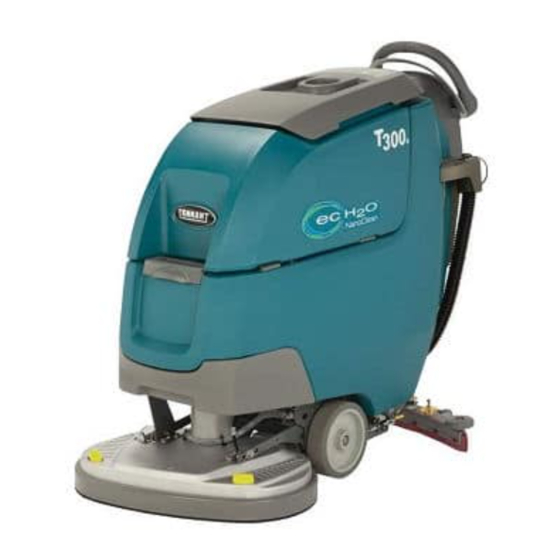
- Page 1 TENNANT T300 SCRUBBER DRYER OPERATOR MANUAL Clemas & Co. Unit 5 Ashchurch Business Centre, Alexandra Way, Tewkesbury, Gloucestershire, GL20 8NB. Tel: 01684 850777 Fax: 01684 850707 Email: info@clemas.co.uk Web: www.clemas.co.uk...
-
Page 2: Intended Use
INTRODUCTION INTENDED USE This manual is furnished with each new model. The automatic floor scrubber is intended for It provides necessary operation and maintenance commercial use, for example in hotels, schools, instructions. hospitals, factories, shops, offices and rental businesses. It is designed to scrub hard floor surfaces Read this manual completely and (concrete, tile, stone, synthetic, etc.) in an indoor understand the machine before... -
Page 3: Table Of Contents
TABLE OF CONTENTS OPERATION MAINTENANCE IMPORTANT SAFETY INSTRUCTIONS ..MAINTENANCE CHART ..... SAFETY LABELS . -
Page 4: Operation
OPERATION IMPORTANT SAFETY INSTRUCTIONS - SAVE THESE INSTRUCTIONS The following warning precautions are used throughout FOR SAFETY: this manual as indicated in their description: 1. Do not operate machine: WARNING: Unless trained and authorized. To warn of hazards or unsafe practices which could result in severe personal Unless operator manual is read and injury or death. - Page 5 OPERATION 4. Before leaving or servicing machine: 6. When loading/unloading machine onto/off truck or trailer: Stop on level surface. Drain tanks before loading machine. Set the parking brake, if equipped. Use a ramp, truck or trailer that can support Turn off machine and remove key. the machine weight and operator.
-
Page 6: Safety Labels
OPERATION SAFETY LABELS The safety labels appear on the machine in the locations indicated. Replace labels if they are missing or become damaged or illegible. WARNING LABEL - FOR SAFETY WARNING LABEL - Batteries emit LABEL - Read Flammable hydrogen gas. manual before materials or Explosion or fire... -
Page 7: Machine Components
OPERATION MACHINE COMPONENTS Scrub Head Types 17 in / 43cm 20 in / 50cm 24 in / 60cm 20 in / 50cm 20 in / 50cm Disk Disk Dual Disk Cylindrical Orbital 1. Cup holder/tray 15. Speed control knob (drive model) 2. -
Page 8: Machine Symbols
OPERATION MACHINE SYMBOLS CONTROL PANEL COMPONENTS T300e Model Control Panel Fast speed (drive model) Slow speed (drive model) Forward / Reverse (drive model) ec-H2O scrubbing (option) Battery charge 1. Service indicator - Lights up when a machine or charger fault is detected. Do not lift by accessory rails 2. -
Page 9: T300 Model With Membrane Control Panel
OPERATION T300 Model with Membrane Control Panel T300 Model with Pro-Panel Controls (LCD - Liquid Crystal Display) 1. Help icon - For first time users. Use to select 1. Service indicator - Lights up when a machine or display language, identify control panel symbols charger fault is detected. -
Page 10: Installing Batteries
OPERATION BATTERY PACK LIFT- OUT TRAY (Option) INSTALLING BATTERIES Models equipped with the optional battery lift-out tray for quick or frequent battery pack exchange. WARNING: Batteries emit hydrogen gas. FOR SAFETY: Before leaving or servicing machine, Explosion or fire can result. Keep sparks and open stop on level surface, turn off machine, remove key flame away when charging. -
Page 11: How The Machine Works
OPERATION HOW THE MACHINE WORKS BRUSH AND PAD INFORMATION Conventional scrubbing: For best cleaning results use the appropriate brush or When using the conventional scrubbing mode, water pad for your cleaning application. Listed below are and detergent mixture from the solution tank flows to brushes and pads and the applications for which each the floor and the rotating brush(es)/pad(s) scrub the is best suited. -
Page 12: Machine Setup
OPERATION INSTALLING BRUSH/PAD - 3 Lug Disk (T300e) MACHINE SETUP FOR SAFETY: Before leaving or servicing machine, stop on level surface, turn off machine, remove key and set parking brake if equipped. ATTACHING SQUEEGEE ASSEMBLY 1. Step down on the scrub head lift pedal to raise the FOR SAFETY: Before leaving or servicing machine, scrub head off the floor (Figure 8). -
Page 13: Installing Brush/Pad - Insta-Click Magnetic Disk
OPERATION Dual disk model - Turn the brush motor hub until the lug slot with spring clip is visible. Position the INSTALLING BRUSH/PAD - Insta-Click Magnetic three lugs into the motor hub slots and give the pad Disk driver/brush a quick turn towards the spring clip FOR SAFETY: Before leaving or servicing machine, (Figure 11). -
Page 14: Installing Pad - Orbital
OPERATION 4. To remove the pad driver(s)/brush(es), raise the 2. Install the backer pad, retaining strips facing scrub head and press the yellow plunger button outward, to bottom of scrub head (Figure 20). with foot or hand (Figure 17). Pad will drop to floor. Make sure pad is centered on scrub head. -
Page 15: Filling Solution Tank
OPERATION 2. Remove the debris tray by sliding it out from the scrub head (Figure 23). FILLING SOLUTION TANK FOR SAFETY: Before leaving or servicing machine, stop on level surface, turn off machine, remove key and set parking brake if equipped. Remove the solution tank lid and fill the solution tank. -
Page 16: Filling Severe Environment Tank (T300 Ec-H2O Model Option)
OPERATION 3. Adjust the mixing ratio knob according to the FILLING SEVERE ENVIRONMENT TANK cleaning detergent’s mixing instructions (Figure 31). (T300 ec-H2O model Option) The ec-H2O NanoClean model may come equipped with the optional Severe Environment mode. The Severe Environment button allows you to dispense cleaning detergent as needed for excessive soil buildup. -
Page 17: Accessory Rails
OPERATION To install the accessory clips, hook the clip over the rail ACCESSORY RAILS and push downward until it snaps into position. To remove the accessory clip, reach under the clip and The machine is equipped with one or two accessory carefully pull the latch tab downward to release from rails which straddle the control console. -
Page 18: T300 Control Panel Operation
OPERATION 4. Models equipped with Severe Environment button option - Press Severe Environment button one T300 CONTROL PANEL OPERATION time to dispense cleaning detergent for 30 seconds (Figure 41). A green LED in the corner will blink slowly when dispensing. During the last 5 seconds, T300 WITH MEMBRANE CONTROL PANEL the LED will blink rapidly as an alert that the dispensing is about to stop. -
Page 19: T300 Model With Pro- Panel Controls
OPERATION To change the Zone Settings for a specific scrubbing application, configure the new zone T300 MODEL WITH PRO- PANEL CONTROLS settings and press and hold the zone button until it There are two types of user modes that will interface blinks three times to save new zone setting. - Page 20 OPERATION When supervisor controls are configured for the operator mode, a login screen will appear at start Press the solution flow icon to display the up (Figure 47 ). Enter the login number assigned solution flow scale (Figure 50). Press the (+) symbol by the supervisor and press the green arrow to to increase solution flow.
- Page 21 OPERATION NOTE: When the severe environment mode is NOTE: The Severe Environment and ec-H2O turned on, the down pressure and solution flow modes cannot be configured together. settings automatically increase to the high setting. When turned off, the settings revert back to the original settings.
- Page 22 OPERATION Red or Yellow ec-H2O system fault icon (Figure Tutorials button - Includes videos on how to 62). See SERVICE INDICATOR CODES to diagnose ec-H2O system fault. perform specific operation and maintenance procedures. Press the video icons to start videos When the ec-H2O system fault icon is blinking (Figure 59).
-
Page 23: Machine Operation
OPERATION ATTENTION: If cleaning detergent is accidentally cycled through ec-H2O system, immediately turn the MACHINE OPERATION ec-H2O system off. Drain solution tank, refill with cool water and operate the ec-H2O system to flush out FOR SAFETY: Do not operate machine unless detergent. - Page 24 OPERATION 6. Drive models - push the directional lever to the 9. T300e ec-H2O model - To adjust the solution flow forward position to go forward (Figure 68). To rate when ec-H2O scrubbing, press the solution reverse the machine pull the directional lever flow button located on the ec-H2O module (Figure backwards.
-
Page 25: While Operating Machine
OPERATION WHILE OPERATING MACHINE EMERGENCY SHUT-OFF BUTTON (Drive models) Push the emergency shut-off button in the event of an WARNING: Flammable materials materials or emergency (Figure 75). This red button shuts off all reactive metals can cause an explosion or fire. Do power to machine. -
Page 26: Circuit Breaker Panel
OPERATION CIRCUIT BREAKER PANEL DRAINING TANKS The machine is equipped with resettable circuit breakers to protect the machine from a current FOR SAFETY: Before leaving or servicing machine, overload. If a circuit breaker trips, disconnect the stop on level surface, turn off machine, remove key battery cable connection and reset the breaker by and set parking brake if equipped. -
Page 27: Draining Solution Tank
OPERATION 4. T300 models - Remove the debris tray and empty 3. Rinse out solution tank with clean water (Figure (Figure 81). 84). FIG. 81 FIG. 84 5. Rinse out the recovery tank with clean water and 4. Remove the solution tank filter and clean screen wipe clean of any soil residue (Figure 82). -
Page 28: Service Indicator Codes
OPERATION SERVICE INDICATOR CODES When the machine or battery charger detects a fault, the service indicator will flash. A fault code will be provided to determine problem as described below. T300 Pro-Panel Controls (LCD) T300e/T300 Control Panels Flashing service indicator Press icon to access fault code screen Fault code screen... - Page 29 OPERATION SERVICE INDICATOR CODES - Continued LCD Fault LED Fault Code Code = Flashing CAUSE SOLUTION 0x0503 Vacuum motor over current. Contact service. S 0x0504 0x0505 Vacuum motor shorted fault. Contact service. S S S 0x0506 0x0603 Severe environment detergent...
- Page 30 OPERATION ec-H2O SYSTEM SERVICE INDICATOR CODES - OPTION T300 Pro-Panel Controls (LCD) T300e/T300 Control Panel Flashing service indicator Press icon to access fault code screen Fault code screen Solid or Red or yellow ec-H2O Flashing blinking Red Flashing system fault icon LED fault ec-H2O service...
-
Page 31: Maintenance
MAINTENANCE MAINTENANCE CHART Person Interval Resp. Description Procedure Pad(s) Check, flip or replace Daily Brush(es) Check, clean Cylindrical Brushes Check, clean Recovery tank Drain, rinse, clean float shut-off screen and debris tray if equipped Solution tank Drain, rinse Severe environment tank (option) Check, refill Squeegee Clean, check for damage and wear... -
Page 32: Machine Maintenance
MAINTENANCE 4. Drain and rinse out the solution tank (Figure 89). MACHINE MAINTENANCE To keep the machine in good working condition, simply perform the following maintenance procedures. FOR SAFETY: Before leaving or servicing machine, stop on level surface, turn off machine, remove key and set parking brake if equipped. -
Page 33: After Weekly Use
MAINTENANCE 7. Wipe the squeegee blades clean. Inspect blades 11. Severe environment option - Refill the severe for wear and damage (Figure 93). Rotate blade if environment tank with a recommended cleaning worn. See SQUEEGEE BLADE REPLACEMENT. detergent at full concentration (Figure 97). Replace cap. -
Page 34: After Every 50 Hours Of Use
MAINTENANCE AFTER EVERY 50 HOURS OF USE AFTER EVERY 100 HOURS OF USE If machine is equipped with the optional battery 1. Remove the solution tank filter and clean screen watering system, check the watering hoses and (Figure 101). Turn the filter bowl counter-clockwise connections for damage and wear (Figure 105). -
Page 35: Belts
MAINTENANCE BELTS BATTERIES FOR SAFETY: Before leaving or servicing machine, stop on level surface, turn off machine, remove key FOR SAFETY: Before servicing machine, stop on and set parking brake if equipped. level surface, turn off machine, remove key and set parking brake if equipped. -
Page 36: Checking Connections / Cleaning
MAINTENANCE CHARGING BATTERIES The charging instructions in this manual are intended for the battery charger supplied with your machine. The use of other battery chargers that are not supplied and approved by Tennant are prohibited. If your machine is equipped with an off-board battery charger refer to the charger’s owners manual for operating instructions. -
Page 37: Battery Charger Settings
MAINTENANCE For models equipped with off-board chargers, first connect the charger’s DC cord into the machine’s BATTERY CHARGER SETTINGS battery charge receptacle then plug the AC power The battery charger is set to charge the battery type supply cord into a properly grounded wall outlet supplied with your machine. - Page 38 MAINTENANCE 4. Disconnect the battery cable, power cord and wire * The factory setting, dial position “0”, is pre-programmed to accommodate the battery type supplied with new harness from charger. Using a T25 star screwdriver, remove the four screws that mount machine.
-
Page 39: Squeegee Blade Replacement
MAINTENANCE 5. Squeeze the squeegee frame and blade retainer together and re-tighten the two outside knobs SQUEEGEE BLADE REPLACEMENT (Figure 125). FOR SAFETY: Before leaving or servicing machine, stop on level surface, turn off machine, remove key and set parking brake if equipped. Each squeegee blade has four wiping edges. -
Page 40: Ec-H2O Nanoclean Water Conditioning Cartridge Replacement
MAINTENANCE 4. Fill in the installation date on the new cartridge label (Figure 128). ec-H2O NanoClean WATER CONDITIONING CARTRIDGE REPLACEMENT FOR SAFETY: Before leaving or servicing machine, stop on level surface, turn off machine, remove key and set parking brake if equipped. The water conditioning cartridge is required to be replaced when it reaches its maximum water usage or expiration time of when the cartridge was activated,... -
Page 41: Loading/Unloading Machine For Transporting
MAINTENANCE LOADING/UNLOADING MACHINE FOR STORING MACHINE TRANSPORTING The following steps should be taken when storing the When transporting the machine by use of trailer or machine for extended periods of time. truck, carefully follow the loading and tie-down 1. Charge the batteries before storing machine to procedure: prolong the life of the batteries. -
Page 42: Troubleshooting
MAINTENANCE TROUBLESHOOTING PROBLEM CAUSE SOLUTION Service indicator icon is Machine or on-board battery charger See SERVICE INDICATOR CODES blinking fault has been detected ec-H2o indicator icon is ec-H2O system fault has been See SERVICE INDICATOR CODES red or blinking red detected Machine will not operate Emergency stop button activated... - Page 43 MAINTENANCE TROUBLESHOOTING - Continued PROBLEM CAUSE SOLUTION Trailing water - poor or Full recovery tank or excessive foam Drain recovery tank not water pickup buildup Loose drain hose cap or flow control Replace cap or close flow control valve on valve is open drain hose Worn squeegee blades...
-
Page 44: Specifications
SPECIFICATIONS GENERAL MACHINE DIMENSIONS/CAPACITIES/PERFORMANCE MODEL 43 cm Disk (Push) 50 cm Disk (Push) 43 cm Disk (Drive) 50 cm Disk (Drive) Length 1302 mm 1372 mm 1302 mm 1372 mm Width 508 mm 559 mm 508 mm 559 mm Height 1095 mm 1095 mm 1095 mm... - Page 45 SPECIFICATIONS GENERAL MACHINE DIMENSIONS/CAPACITIES/PERFORMANCE MODEL 60 cm Dual Disk 50 cm Cylindrical Brush 50 cm Orbital Length 1314 mm 1283 mm 1245 mm Width 660 mm 635 mm 521 mm Height 1095 mm 1095 mm 1095 mm Weight 113 kg 113 kg 216 kg Weight (with batteries)
-
Page 46: Machine Dimensions
SPECIFICATIONS MACHINE DIMENSIONS SINGLE DISK MODEL 772 mm 1095 mm 1302 mm 508 mm 43 cm Model 43 cm Model 1372 mm 559 mm 50 cm Model 50 cm Model Tennant T300e/T300 (03- 2015) - Page 47 SPECIFICATIONS DUAL DISK MODEL 772 mm 1095 mm 660 mm 1314 mm Tennant T300e/T300 (03- 2015)
- Page 48 SPECIFICATIONS CYLINDRICAL BRUSH MODEL 772 mm 1095 mm 1283 mm 635 mm Tennant T300e/T300 (03- 2015)
- Page 49 SPECIFICATIONS ORBITAL PAD MODEL 772 mm 1095 mm 1245 mm 521 mm Tennant T300e/T300 (03- 2015)
- Page 50 SPECIFICATIONS Tennant T300e/T300 (03- 2015)
-
Page 51: Supervisor Controls
SUPERVISOR CONTROLS ATTENTION: The following instructions are intended Hold down the Zone Setting button until it blinks for supervisor use only. Remove pages from manual if three times to save the preferred supervisor control mode (Figure 133). In this example, Lockout mode necessary. - Page 52 SUPERVISOR CONTROLS T300 MODEL WITH PRO-PANEL CONTROLS There are two types of user modes that will interface with the operator home screen: Operator Mode - Capable of machine operation with permissions and restrictions controlled by the supervisor. Supervisor Mode - Capable of machine operation with full use of all controls, along with configuring permissions and restrictions for the operator mode.
- Page 53 SUPERVISOR CONTROLS Press the “Add Profile” button to add a new user profile (Figure 140). FIG. 143 6. Now select the controls that the new user should have access to use (Figure 144). Green represents unlocked controls and gray represents locked FIG.
- Page 54 SUPERVISOR CONTROLS 9. Now at machine start up, a login screen will display To change the factory-assigned default supervisor (Figure 147). The new user will need to enter their login number, press the Supervisor button. Then assigned login number to operate machine press the “DEFAULT SUPER”...
- Page 55 SUPERVISOR CONTROLS b. Press the “yes” button to enter the Default d. Select a pre-assigned user profile. In this User screen (Figure 153). example, operator profile “JOHN” is selected (Figure 155). Turn the key off to apply the setting. FIG. 153 c.
Need help?
Do you have a question about the TENNANT T300 and is the answer not in the manual?
Questions and answers