Table of Contents
Advertisement
Quick Links
Advertisement
Table of Contents

Related Manuals for RAMSET TRAKFAST


Summary of Contents for RAMSET TRAKFAST
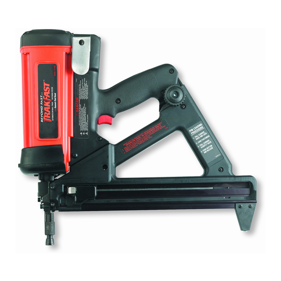
- Page 1 TRAKFAST REPAIR MANUAL TRAKFAST REPAIR MANUAL Tool Repair Manual...
-
Page 2: Table Of Contents
TRAKFAST REPAIR MANUAL TABLE OF CONTENTS Safety Instructions ............... . .3 Tool Operation Overview . - Page 3 TRAKFAST REPAIR MANUAL • 5/32” Hex Key • Inside Snap Ring Pliers • Outside Snap Ring Pliers • #2 Phillips Screwdriver • T15 Torx Screwdriver • T25 Torx Screwdriver • T7 Torx Screwdriver • Flat Blade Screwdriver • Needle Nose Pliers •...
-
Page 4: Safety Instructions
DANGER DANGER ALWAYS keep the TrakFast tool, fuel cell, battery and The TrakFast tool is an internal combustion battery charger out of the reach of children. devise. It produces hot exhaust gases that may ignite flammable materials. - Page 5 11. DO NOT drive fasteners too close or on top of other fasteners. The TrakFast tool is not a toy — it is a tool. Careless and improper use may result in a serious accident. A fastener may ricochet and cause serious injury.
- Page 6 Do not use a defective battery charger, one that erly. NOTE: DEAD BATTERY MUST BE overheats and/or smokes when plugged in. RETURNED TO YOUR LOCAL TRAKFAST DISTRIBUTOR FOR PROPER DISPOSAL. Plug the battery charger into a 120V AC outlet only.
-
Page 7: Tool Operation
TRAKFAST REPAIR MANUAL TOOL OPERATION OVERVIEW This assembly generates and controls forces that drive Magazine Assembly the fasteners. It will require the majority of routine service and/or repair. The magazine assembly has two functions. Its primary func- tion is to store and feed fasteners into the nose of the tool. -
Page 8: Start And Pre-Combustion
TRAKFAST REPAIR MANUAL TOOL OPERATION START and PRE-COMBUSTION When lower probe (E) is pressed against the work surface, cage (F) is forced against the spring (G). Combustion chamber (H) is raised up against cylinder head (I), and O-Rings (J & M) seal off the combustion chamber, creating an air tight seal. -
Page 9: Combustion
TRAKFAST REPAIR MANUAL TOOL OPERATION Combustion Depressing the trigger activates the ignition circuit. This causes a spark (N) to jump the gap between the spark element and cylinder head, igniting the fuel/air mixture in the combustion chamber. Pis- ton assembly (O) is forced downward driving the fastener into the work surface. -
Page 10: Power/Exhaust
TRAKFAST REPAIR MANUAL TOOL OPERATION Power/Exhaust Downward movement of the piston assembly, past exhaust ports (P), allows exhaust gases to exit. The pressure of the exhaust gases against the flat washer compresses the wave washers, allowing the gases to flow through the mid-check area (Q) and out of the tool through the exhaust ports in the bot- tom of the housing (R). -
Page 11: Return
TRAKFAST REPAIR MANUAL TOOL OPERATION Return Reduced pressure within the combustion chamber allows wave washers (T) to reseal the combustion chamber. Rapid cooling of gases trapped in the combustion chamber (U) creates vacuum. This vacuum is strong enough to lift and hold the pis- ton assembly in its starting position. -
Page 12: Purging
TRAKFAST REPAIR MANUAL TOOL OPERATION Purging The combustion chamber drops when the tool is lifted from the work surface and the trigger is re- leased. This opens the seal between the combustion chamber and cylinder head O-Ring (W) and sleeve O-Ring (X). -
Page 13: Preparing Tool For Operation - Battery/Charger Troubleshooting
TRAKFAST REPAIR MANUAL TROUBLESHOOTING Preparing Tool for Operation — Battery/Charger Problems SYMPTOM POSSIBLE PROBLEMS SERVICE Battery Cell doesn’t appear to ac- Inoperative indicator lights on Char- Try Battery Cell in tool after charge cept charge — green Charger light ger. -
Page 14: Tool Disassembly
TRAKFAST REPAIR MANUAL TOOL DISASSEMBLY DANGER ALWAYS TAKE THE FOLLOWING PRECAUTIONS BEFORE ANY SERVICE OR ROUTING MAINTENANCE IS PERFORMED: • REMOVE FASTENERS • REMOVE FUEL CELL • REMOVE BATTERY REMOVE THE MAGAZINE ASSEMBLY Loosen and remove knob (part #801124). Slide the magazine back and away from nose. -
Page 15: Handle Assembly - Part 1
TRAKFAST REPAIR MANUAL TOOL DISASSEMBLY REMOVE HANDLE ASSEMBLY (Part 1) Lift off cap, grill and filter with screw driver. Loosen four screws using a 5/32” hex key (Part # 7405061). Lift off cap assembly (Part # 401365). Rev. 09/07... - Page 16 TRAKFAST REPAIR MANUAL REMOVE HANDLE ASSEMBLY (Part 1) Remove Screw at bottom of Handle Assembly (Part # 7405065). Remove Cam Bushing.(Part # 401397). Push Cam Bushing out of Handle from side where the Screw was removed. Rev. 09/07...
-
Page 17: Motor/Cylinder Head Assembly
NEVER attempt to operate tool without cap assembly securely fastened. Cap assembly secures cylinder head to combustion chamber. Operating TrakFast with cap assembly off or loose will cause burn- ing fuel to escape through top of tool, causing burns and damage to tool. - Page 18 TRAKFAST REPAIR MANUAL TOOL DISASSEMBLY Motor/Cylinder Head Assembly Torque Head Switch to 5-10 in-lbs. Torque Spark Plug to 20-25 in-lbs. Install Stem Adapter as illustrated. Notice the difference between one end of the Sleeve to the other. One side of the sleeve has a rib. The other side does not. The ribs should be to the inside and should touch the fan motor.
- Page 19 TRAKFAST REPAIR MANUAL Motor/Cylinder Head Assembly (cont’d) Apply a small amount of oil or lubricant to the inside of the bore where the Fan Motor is positioned. Insert Motor Assembly as illustrated. The Motor Sleeve orientation will determine how well the spacing will be around the shaft.
- Page 20 TRAKFAST REPAIR MANUAL TOOL DISASSEMBLY Motor/Cylinder Head Assembly (cont’d) Make sure the “flat” side of the shaft is where the Set Screw on the Fan Blade will be tightened. Position the Fan Blade approximately .120” away from the bottom of the cylinder head. Feeler Gages or an 1/8” drill bit works well as a spacer.
- Page 21 TRAKFAST REPAIR MANUAL TOOL DISASSEMBLY CYLINDER HEAD ASSEMBLY KEY PART NO. DESCRIPTION 401365 Cap, grill & filter assembly 7505018 Foam filter only 901065A Screw kit, #10-24 x 1-1/4” Sems (pkg. 4) 900271 P.C board assembly 7405090 P.C board screw & washer, #8-32 x 1/2” (pkg. 3)
-
Page 22: Handle Assembly - Part 2
TRAKFAST REPAIR MANUAL TOOL DISASSEMBLY Handle Assembly (part 2) Remove Trigger Cam (part #401396). Remove Belt Hook and screw. (screw, part #7405065) (Belt Hook, part #401495) Remove (3) screws (part #7405067). Remove (1) screw (part #7405066). Lift off Handle half. - Page 23 TRAKFAST REPAIR MANUAL TOOL DISASSEMBLY Handle Assembly - Part 2 (cont’d) Remove Trigger and Spring from Handle. (Trigger, part #401394A) (Spring, part #401395) Remove Trigger Switch with screw driver. Undo the two screws and lift out. Unplug from the Spark Unit.
- Page 24 TRAKFAST REPAIR MANUAL TOOL DISASSEMBLY TOOL DISASSEMBLY Handle Assembly - Part 2 (cont’d) Lift up Spark Plug wire and remove from Handle half (part #7505166). Unplug Spark Wires from Spark Unit. Lift up with screw driver to remove Spark Unit (part #7405163).
- Page 25 TRAKFAST REPAIR MANUAL TOOL DISASSEMBLY Handle Assembly - Part 2 (cont’d) Remove Fan Blade Set Screw (requires #T-7). (Fan Blade part #403167 with screw) With Phillips screw driver remove (3) screws (part #7405090) holding P.C. Board. Unplug Fan Connector. Pull out red Stem Adapter (part #401340).
- Page 26 TRAKFAST REPAIR MANUAL TOOL DISASSEMBLY Handle Assembly - Part 2 (cont’d) Remove Spark Plug (part #7505164). Fan Motor Kit (part #900525A). See inserts for Motor/Cylinder Assembly. Rev. 09/07...
- Page 27 TRAKFAST REPAIR MANUAL TOOL DISASSEMBLY Handle Assembly KEY PART NO. DESCRIPTION 7405163 Spark Unit (MSU) 7505166 Red Wire and Boot Only (MSU) (For tools after serial no. 398091440) 900012 Wire Cover Plate 404619 Insulator (under Trigger Switch) 404490 Trigger Switch...
-
Page 28: Magazine Assembly
TRAKFAST REPAIR MANUAL TOOL DISASSEMBLY Magazine Assembly Remove (2) screws holding Foot (part #7505146). Remove Foot (part #801113). Pull off Magazine. Remove Lower Rail (part #801110). Pull and slide out rear of Magazine. Remove (3) screws from Magazine (part #7405070). - Page 29 TRAKFAST REPAIR MANUAL TOOL DISASSEMBLY Magazine Assembly (cont’d) Remove (2) screws from Shear Block (part #7405147). Remove Magazine halves (part #7405149). Remove Upper Rail (part #801112). Inspect Upper Rail for heavy burrs. Remove Cover Plate (part #7506006). Rev. 09/07...
- Page 30 TRAKFAST REPAIR MANUAL TOOL DISASSEMBLY Magazine Assembly (cont’d) Remove Battery Contact (part #7505017). Inspect Battery Contact for bent or broken terminals. Replace Contact Assembly if these conditions exist. Remove Shear Block. Take out (2) screws (part #7405147). Shear Block (part #7405145).
- Page 31 TRAKFAST REPAIR MANUAL TOOL DISASSEMBLY Magazine Assembly (cont’d) Remove Carrier Assembly from Magazine half. CAUTION Hold Carrier firmly and slide forward to front of Magazine towards the post and lift Constant Force Spring off post (part #7405168). Remove Lockout Bracket screw (part #801122).
- Page 32 TRAKFAST REPAIR MANUAL TOOL DISASSEMBLY Magazine Assembly (cont’d) Remove pin from Spring Carrier/Follower Assembly (part #7405168). Remove spring from Carrier (part #7405168). Rev. 09/07...
- Page 33 TRAKFAST REPAIR MANUAL TOOL DISASSEMBLY Magazin mbl bly ly K K EY EY PART NO. PART NO RT NO. IPTION PTIO PTION N 14 14 07 07 7 0 07 7 1 071 1 14 4 6 1 1 3...
-
Page 34: Housing Assembly
TRAKFAST REPAIR MANUAL TOOL DISASSEMBLY Housing Assembly Remove (3) screws (part #7405060). Lift off Dust Shield (part #7505013). Lift off Housing (part #7505148). Lift off Nosepiece Assembly (part #801130A). Rev. 09/07... - Page 35 TRAKFAST REPAIR MANUAL TOOL DISASSEMBLY TOOL DISASSEMBLY Housing Assembly (cont’d) Remove Piston Stop Retaining Ring (part #401328), using Snap Ring pliers (part #401333). Make sure when you reassemble that Retaining Ring ends are not positioned in the vertical notches in the Sleeve.
- Page 36 TRAKFAST REPAIR MANUAL TOOL DISASSEMBLY Housing Assembly (cont’d) Slide off Cage and Spring. (part #7405144 only comes as an assembly) (Spring, part #401488) Lift out Mid-check Retaining Ring (part #401322). Remove with Snap Ring Pliers (part #401333). Remove 2 Wave Washers and 1 Seal Washer (part #7405056).
- Page 37 TRAKFAST REPAIR MANUAL TOOL DISASSEMBLY Housing Assembly (cont’d) Lift off O-Ring (part #404482). Lift off Piston Rings (part #7405055). Always make sure the Piston Ring end gaps are opposite each other. Rev. 09/07...
-
Page 38: Nose Assembly
TRAKFAST REPAIR MANUAL TOOL DISASSEMBLY Nose Assembly Remove (2) screws (part #7405059). Lift off Stop Plate (part #801127). Lift off Lock-out Probe (part #801128). Lift off Work Contact Element (part #801129). Inspect Work Contact Element for burring or damage. Replace if burring or damage is noted. - Page 39 TRAKFAST REPAIR MANUAL TOOL DISASSEMBLY Nose Assembly (cont’d) Remove (2) screws (part #7405059). Lift off Guide Block (part #801131). Slide out Upper Probe (part #801132). Inspect rubber Grommet for damage. Replace Upper Probe if grommet is damaged. Rev. 09/07...
-
Page 40: Tool Reassembly
TRAKFAST REPAIR MANUAL TOOL REASSEMBLY Original Nosepiece KEY PART NO. DESCRIPTION KEY PART NO. DESCRIPTION 401322 Mid-Check Retaining Ring 401313 Air Dam 401488 Cage Spring 7405171 Combustion Chamber (w/Air Dam) 092769 Screw, #10-32 x 1/4” 25A 900234 Cage 7405057 Upper Probe with Grommet... - Page 41 TRAKFAST REPAIR MANUAL TOOL REASSEMBLY Telescoping Nosepiece KEY PART NO. DESCRIPTION 401313 Air Dam KEY PART NO. DESCRIPTION 7405171 Combustion Chamber (w/Air Dam & Cage) 092769 Screw, #10-32 x 1/4” 25A 900234 Cage 801132 Upper Probe with Grommet 401330 Chamber Lockout Bar...
-
Page 42: Magazine Assembly
TRAKFAST REPAIR MANUAL TOOL REASSEMBLY Magazine Assembly Place Shear Block in Magazine Assembly (part #7405145). Secure with screws (part #7405147). Check Shear Block for any damage. Place Battery Clip in Magazine Half (part #401422). Secure with screw (part #401423). Check for any damage. - Page 43 TRAKFAST REPAIR MANUAL TOOL REASSEMBLY Magazine Assembly Place Cover Plate in Magazine Assembly (part #7506006). Notice position of notch. It should be placed toward the bottom/ rear of Magazine. Place Upper Rail in Magazine Half (part #801112). Check for any damage.
- Page 44 TRAKFAST REPAIR MANUAL TOOL REASSEMBLY Magazine Assembly Slide Carrier all the way back to the lock position (part #7405168). Place Magazine Halves together (part #7405149). Secure with screws . (part #7405070, 3 each) (part #7405071, 1 each) (Shear Block screws, part #7405147) Slide Lower Rail into Magazine Halves (part #801110).
- Page 45 TRAKFAST REPAIR MANUAL TOOL REASSEMBLY Magazine Assembly TESTING OPERATION OF HANDLE ASSEMBLY Place Handle Assembly on to the Magazine Assembly. Screw on the Knob. This will hold the handle on the Magazine. Place Battery in Magazine. You will have a green light. If you have a red light, you will need to check the Battery or the Battery Contact.
-
Page 46: Handle Assembly - Part 2
TRAKFAST REPAIR MANUAL TOOL REASSEMBLY Handle Assembly - part 2 Spark Unit (part #7405163). Remove any silicone residue from Handle. Place new silicone in Handle. Press Spark Unit into Handle. Replace the unit if it does not spark. Push red wire into Spark Unit and route the wires into the Handle. - Page 47 TRAKFAST REPAIR MANUAL TOOL REASSEMBLY Handle Assembly - part 2 Place plastic wire cover over wires. Make sure all wires are seated properly in handle.vva Place Trigger Switch on top of the wire cover. Secure with screws. Check for any damage.
- Page 48 Replace cylinder head if cracked or broken. Replace O-Ring after cleaning, worn or pinched. Drop oil on O-Ring. ONLY use TrakFast oil or Paslode Impulse oil (do not use grease). Replace Fan Blade if bent or if replacing the Fan Motor.
- Page 49 TRAKFAST REPAIR MANUAL TOOL REASSEMBLY Handle Assembly - part 2 Place Actuator inside the Handle. Note the position of the handle. Replace if broken or damaged. Check all wires before placing Handle half. Secure with screws. Pull Trigger to make sure it is in correct position.
- Page 50 TRAKFAST REPAIR MANUAL TOOL REASSEMBLY Handle Assembly - part 2 Place Handle half on Magazine Assembly. Place Battery in Magazine. For testing, push Head Switch then pull Trigger. This will activate the Fan Motor and Spark Unit. CAUTION Keep fingers away from Fan!
-
Page 51: Housing Assembly
The Bumper is marked “top”. It should be oriented so the word “top” is visible. Replace O-Ring if it has been pinched, worn or after cleaning. Lubricate the O-Ring with TrakFast or Paslode Impulse oil (DO NOT use grease). • Install Flat Seal Washer •... - Page 52 Housing Assembly - (cont’d) Slide the Combustion Chamber on to Sleeve Mid-Check Assembly. Check for any damage on parts. Lubricate sealing surfaces on Combustion Chamber with TrakFast or Paslode oil prior to assembling the sleeve. Place Lockout Bracket in holes.
- Page 53 Check to make sure Piston is not too short. If length is too short, the tool will not shoot overhead or drive fasteners properly. Lubricate Piston Rings and inside of Sleeve Bore with TrakFast or Paslode Impulse oil prior to assembly.
- Page 54 TRAKFAST REPAIR MANUAL TOOL REASSEMBLY Housing Assembly - (cont’d) Place Nosepiece Assembly on Mid-check Assembly. Note how parts line up. Slide Housing over Nosepiece and Mid-check Assembly. Note the position of the Lockout Bar. Slide Dust Shield over Nosepiece. Secure with screws.
- Page 55 TRAKFAST REPAIR MANUAL TOOL REASSEMBLY Housing Assembly - (cont’d) Slide Handle Assembly into Housing. Keep Handle Assembly straight so that the fan does not hit the inside of Chamber. Line up Cam with Housing. Place Cam Bushing inside the Cam and Housing.
- Page 56 TRAKFAST REPAIR MANUAL TOOL REASSEMBLY Housing Assembly - (cont’d) Place Grill on Cap Assembly. Slide in and tap down. Place Shear Block into Nosepiece. Slide Magazine onto Handle/Housing Assembly. Secure Magazine Assembly and Housing together with Knob. Place Battery in Tool.
-
Page 57: Nosepiece Assembly (Original Nosepiece)
TRAKFAST REPAIR MANUAL TOOL REASSEMBLY Nosepiece Assembly — Original Nose Original Nose piece (part #801114A). Roll pins (part #7405058). Check for any damage. Replace Roll Pins if loose. Slide Lower Probe in Nosepiece (part #7505057). Replace Probe if bent or grommet is worn or missing. -
Page 58: Nosepiece Assembly (Telescoping Nosepiece)
TRAKFAST REPAIR MANUAL TOOL REASSEMBLY Nosepiece Assembly — Telescoping Nose Telescoping Nosepiece Assembly (part #801130A). Check for any damage. Nose and Flange should be tight and without movement. Slide Lower Probe into Nosepiece. Replace Probe if bent or grommet is worn or missing. - Page 59 TRAKFAST REPAIR MANUAL TOOL REASSEMBLY Nosepiece Assembly — Telescoping Nose Slide Lockout Probe onto Work Element. Check for any damage. If the Work Element is burred, the fasteners will not flow into the firing position. Slide Lockout Probe and Work Element onto the Nosepiece.
- Page 60 REASON FOR CHANGE: The “Telescoping Nose” provides improved fastener guidance, thereby increasing fastener “stick” or success rate along with the elimination of plastic jamming in the end of the nose. ACTION REQUIRED: No action required. Please Note: Magnetic probes used for the TrakFast tool are “nose specific”. See photos below.
-
Page 61: Troubleshooting Guide
TRAKFAST REPAIR MANUAL TROUBLESHOOTING GUIDE PROBLEM SOLUTION Fan motor does not run. • Check Battery • Check for solid green light • Red light — check Battery Contact (7505017) • Check Fan Motor and Head Switch connectors • Check Fan Motor (7405164) •... - Page 62 Always check the tool for proper operation before placing it back in service, but before operating the tool for the first time after performing service, go through the following checklist: • Make sure all parts removed during service have been replaced in the tool. Do not attempt to operate the TrakFast tool if there are extra parts left over after assembly.
- Page 63 TRAKFAST REPAIR MANUAL TROUBLESHOOTING GUIDE PREPARING TOOL FOR OPERATION — TOOL PROBLEMS SYMPTOM POSSIBLE PROBLEMS SERVICE Fasteners do not slide freely into Pin or pins not properly collated. Use strip with proper collation. Magazine; strip does not advance into Damaged strip.
- Page 64 TRAKFAST REPAIR MANUAL TROUBLESHOOTING GUIDE PREPARING TOOL FOR OPERATION — BATTERY/CHARGER PROBLEMS PREPARING TOOL FOR OPERATION — BATTERY/CHARGER PROBLEMS PREPARING TOOL FOR OPERATION — BATTERY/CHARGER PROBLEMS SYMPTOM POSSIBLE PROBLEMS SERVICE Battery Cell doesn’t appear to accept Inoperative indicator lights on Charger.
- Page 65 TRAKFAST REPAIR MANUAL TROUBLESHOOTING GUIDE NORMAL STAGE OF OPERATION Symptom Possible Problems Service Fan not running – tool LED is off. Battery Cell not charged. Charge Battery Cell according to Owner’s Manual. Magazine is loose, preventing current Make sure Magazine is tight to nose flow from Magazine to Handle and...
- Page 66 Cylinder Head O-Ring is dry or not Lubricate Cylinder Head O-Ring with seated in groove properly. TrakFast Lubricating Oil or replace O-Ring if O-Ring does not seat in groove. Upper Sleeve O-Ring is dry or not Lubricate O-Ring with TrakFast Lubri- seated in groove properly.
- Page 67 TRAKFAST REPAIR MANUAL TROUBLESHOOTING GUIDE POWER/EXHAUST STAGE OF OPERATION Symptom Possible Problems Service Tool works properly, but pins won’t Check application. Check application. drive fully. Fuel Cell is low. Check Fuel Cell according to Owner’s Manual. Tool works properly, but pins are Bumper is not seated properly in base Seat Bumper properly.
- Page 68 TRAKFAST REPAIR MANUAL TROUBLESHOOTING GUIDE POWER/EXHAUST STAGE OF OPERATION (cont’d) Symptom Possible Problems Service Tool cycles with a “poof” sound – no Piston Rings are damaged or not Check Piston Rings and service as pin is driven. seated properly in piston ring required.