Teka EWF 60 4G AI AL CI Instruction Manual
Hide thumbs
Also See for EWF 60 4G AI AL CI:
- Instructions for the installation and advice for the maintenance (92 pages) ,
- User manual (112 pages) ,
- Instruction manual (84 pages)
Table of Contents
Advertisement
Quick Links
Advertisement
Table of Contents

Subscribe to Our Youtube Channel
Related Manuals for Teka EWF 60 4G AI AL CI


Summary of Contents for Teka EWF 60 4G AI AL CI
- Page 1 Instructions for the installation and advice for the maintenance EWF 60 4G AI AL CI EW 60 4G AI AL CI EWF 90 5G AI AL TR CI EW 90 5G AI AL TR CI Instructions Manual EWF 60 4G AI AL CI...
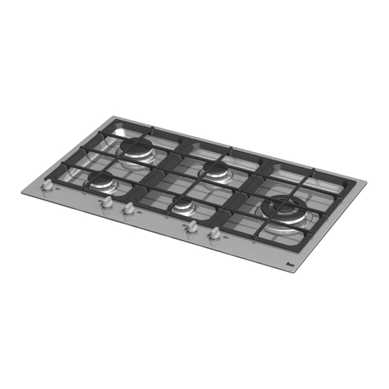
- Page 2 DESCRIPTION OF THE HOT PLATES MODEL: EWF 60 4G AI AL CI MODEL: EWF 90 5G AI AL TR CI EW 60 4G AI AL CI EW 90 5G AI AL TR CI 1 Ultra rapid gas burner of 3100 W...
- Page 3 1) BURNERS - Always place a lid on the pans. - Use only pan with a flat bottom. A diagram is screen-printed above each knob on the front panel. This diagram indicates to which burner the knob in question corresponds. After Burners Power ratings Pan Ø...
- Page 4 Notes: use of a gas cooking appliance produces heat and moisture in the room in which it is installed. The room must therefore be well ventilated by keeping the natural air vents clear (fig. 3) and by activating the mechanical aeration device (suction hood or electric fan fig. 4 and fig. 5). Intensive and lengthy use of the appliance may require additional ventilation.
- Page 5 CLEANING IMPORTANT: - Check that enamelled burner cap “C” (fig. 6) always disconnect the appliance from the gas have correctly positioned on the burner head. and electricity mains before carrying out any It must be steady. cleaning operation. - The exact position of the pan support is established by the rounded corners, which should be set towards the side edge of the 2) HOT PLATE...
-
Page 6: Installation
INSTALLATION TECHNICAL INFORMATION 4) FIXING THE HOT PLATE FOR THE INSTALLER The hot plate has a special seal (in the case of filotop) or putty (in the case of semifilo) which Installation, adjustments of controls and prevents liquid from getting into the cabinet. maintenance must only be carried out by a Strictly comply with the following instructions in qualified engineer. - Page 7 INSTALLATION...
- Page 8 INSTALLATION “FILOTOP” HOT PLATE INSTALLATION R 14 R 14,5 FIG. 10/A FIG. 10/B...
- Page 9 INSTALLATION “SEMIFILO” HOT PLATE INSTALLATION FIG. 11/A FIG. 11/B...
-
Page 10: Room Ventilation
INSTALLATION I M P O RTA N T I N S TA L L AT I O N connection must comply with the pertinent S P E C I F I C AT I O N S standards and provisions in force. When gas is supplied through ducts, the appliance The installer should note that the appliance that side must be connected to the gas supply system:... -
Page 11: Electrical Connection
INSTALLATION 8) ELECTRICAL CONNECTION When the appliance is connected straight to the electricity main: The electrical connections of the appliance - install an omnipolar circuit-breaker between the must be carried out in compliance with the appliance and the electricity main. This circuit- provisions and standards in force. - Page 12 ADJUSTMENTS Always disconnect the appliance from the - Insert a small screwdriver “D” into hole “C” (fig. 13) electricity main before making any adjustments. and turn the throttle screw to the right or left until All seals must be replaced by the technician at the burner flame has been adequately regulated to the end of any adjustments or regulations.
-
Page 13: Replacing The Injectors
CONVERSIONS 10) REPLACING THE INJECTORS seals on the regulating or pre-regulating devices. The envelope with the injectors and the labels can The burners can be adapted to different types of be included in the kit, or at disposal to the gas by mounting injectors suited to the type of gas authorized customer Service Centre. - Page 14 SERVICING Always disconnect the appliance from the Greasing the taps (see fig. 19) electricity and gas mains before proceeding If a tap becomes stiff to operate, it must be with any servicing operation. immediately greased in compliance with the following instructions: 11) REPLACING HOT PLATE PARTS - remove the tap.
- Page 15 SERVICING CABLE TYPES AND SECTIONS TYPE OF TYPE OF SINGLE - PHASE HOT PLATE CABLE POWER SUPPLY Gas hot plate H05 RR - F Section 3 x 0.75 mm ATTENTION!!! If the power supply cable is replaced, the installer should leave the ground wire longer than the phase conductors (fig.
- Page 16 TECHNICAL DATA ON THE DATA LABEL 4 BURNERS 5 BURNERS CATEGORY = II CATEGORY = II 2H3B/P 2H3B/P G 30 - BUTANE = 30 mbar G 30 - BUTANE = 30 mbar G 31 - PROPANE = 30 mbar G 31 - PROPANE = 30 mbar G 20 - NATURAL = 20 mbar G 20 - NATURAL = 20 mbar Gas Natural = 6.95 kW...
- Page 17 TECHNICAL DATA FOR THE APPLIANCE GAS REGULATION...
-
Page 18: Technical Assistance And Spare Parts
TECHNICAL ASSISTANCE AND SPARE PARTS Before leaving the factory, this appliance will have been tested and regulated by expert and specialized personnel in order to guarantee the best performances. Any repairs or adjustments which may be subsequently required may only be carried out by qualified personnel with the utmost care and attention.
Need help?
Do you have a question about the EWF 60 4G AI AL CI and is the answer not in the manual?
Questions and answers