Table of Contents
Advertisement
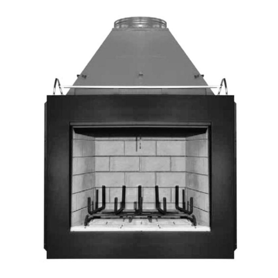
INSTALLATION
INSTRUCTIONS
ESTATE SERIES
48" Wood Burning Fireplaces
P/N 850,006M REV. C 04/2004
LENNOX HEARTH PRODUCTS
MODELS
EST-48
EST-48-H
This installation manual will enable you to obtain a safe, efficient and
dependable installation of your fireplace system. Please read and under-
stand these instructions before beginning your installation.
Do not alter or modify the fireplace or its components under any
circumstances. Any modification or alteration of the fireplace system,
including but not limited to the fireplace, chimney components and
accessories, may void the warranty, listings and approvals of this system
and could result in an unsafe and potentially dangerous installation.
IMPORTANT! TO ASSURE PROPER ALIGNMENT OF GLASS DOORS:
INSTALL THIS FIREPLACE IN A SQUARE AND PLUMB CONDITION,
USING SHIMS AS NECESSARY AT SIDES AND/OR BOTTOM.
PLEASE RETAIN THIS MANUAL FOR FUTURE REFERENCE.
RETAIN THESE INSTRUCTIONS
FOR FUTURE REFERENCE
WH Report No. 629-915173
1
NOTE: DIAGRAMS & ILLUSTRATIONS NOT TO SCALE.
Advertisement
Table of Contents

Related Manuals for Lennox Signature ESTATE EST-48


Summary of Contents for Lennox Signature ESTATE EST-48
- Page 1 INSTALLATION INSTRUCTIONS ESTATE SERIES 48" Wood Burning Fireplaces P/N 850,006M REV. C 04/2004 LENNOX HEARTH PRODUCTS MODELS EST-48 EST-48-H This installation manual will enable you to obtain a safe, efficient and dependable installation of your fireplace system. Please read and under- stand these instructions before beginning your installation.
-
Page 2: Table Of Contents
TABLE OF CONTENTS Safety Rules ... page 2 Tools and Building Supplies ... page 2 Precautions ... page 3 Introduction ... page 3 Clearances/Height Requirements ... page 3 Chimney System ... page 3 Assembly Outline ... page 4 Location of Fireplace ... page 4 Assembly Steps ... -
Page 3: Precautions
PRECAUTIONS Note: These fireplace systems are not difficult to install. However, in the interest of safety, it is recommended that the installer be a quali- fied or certified “tradesman” familiar with com- monly accepted fireplace installation and safety techniques as well as prevailing local codes. The most important areas of concern dealing with the installation of factory-built fireplaces are clearances to combustible materials, proper... -
Page 4: Assembly Outline
Insulate Joists 19" Same As Ceiling (483mm) 19" (483mm) Draft Stops F10FS-2 Firestop FTF13-CT2 Termination Note: Non- Combustible Chase Flashing must be Used to Cover Chase Opening (2.4m) Level Insulation (Thermal Barrier) Figure 2 WARNING: IF INSULATION IS USED, THE FIREPLACE MUST NOT BE PLACED DI- RECTLY AGAINST IT. -
Page 5: Assembly Steps
Black Portion Of Frame Not To Be Covered With Combustible Materials Wall Covering 12” 1” Door Opening Safe 12” Zone Figure 5 ASSEMBLY STEPS Note: The following steps represent the normal sequence of installation. Each installation is unique, however, and might require a different sequence. -
Page 6: Est-48 Fireplace Specifications
2" Metal Safety Strips with 1" Overlap Figure 8 Platform 2" Special “Z” Metal Safety Strips with 1" Overlap Figure 9 IMPORTANT: UNDER NO CIRCUMSTANCES CAN THE FIREPLACE TOP SPACERS ( FIGURE 10 ) BE REMOVED OR MODIFIED, NOR MAY YOU NOTCH THE HEADER TO FIT AROUND OR BE INSTALLED LOWER THAN THE SPACERS. -
Page 7: Framing Specifications
FRAMING SPECIFICATIONS Figure 11 Back Wall of Chase/Enclosure FOAK Including Finising Materials if any Combustion Air Kit Rough Framing Face (Unfinished Inside Chase Shown) Figure 12 Back Wall of Chase/Enclosure FOAK Including Finising Materials Combustion if any Air Kit - Optional Rough Framing Face Outside Chase... -
Page 8: Installing The Chimney System
Anchor Tab Figure 17 Step 4. The fireplace should be secured to the side framing members using the nailing flange. Use 8d nails ( Figure 18 ). Nailing Flange Framing Stud 8d Nail Figure 18 Note: The nailing flange and the area directly behind the nailing flange is exempt from the clearances described on the fireplace clearance label. - Page 9 Step 4. Note: Chimney sections are constructed with a unique locking tab design, which en- sures an immediate, tight assembly between sections. Plan your chimney requirements care- fully before assembly as chimney is difficult to disassemble after installation. If disassembled, the tabs might become damaged.
-
Page 10: Ten Foot Rule Summary
Step 8. The standard Security Chimneys F10 roof flashing assemblies include a storm collar. Slide the storm collar over outer chimney, rest on flashing spacers and align with top surface of flashing. Insert tab in slot, pull tight and bend tab back over slot. -
Page 11: Multiple Terminations
MULTIPLE TERMINATIONS If more than one termination is located in the same chase or within the same general proxim- ity, we suggest they should be separated in distance at least 24" horizontally from flue cen- ter to flue center and stacked or staggered vertically at least 18"... -
Page 12: Vertical Elevation Chart
Height Of Chimney Only Inches Feet/Inches 12" 0 11 2 11 7 11 9 11 17 11 18 10 20 10 22 10 27 10 29 10 35 11 37 11 FTF13 VERTICAL ELEVATION CHART Number Of FTF13 Height Of Chimney Lengths Chimney Only Chimney Only... -
Page 13: Ftf13 Offset Elevation Chart
Figure 36 Joints Chimney Section No. 8 x 1/2" SMS Figure 37 FTF13 OFFSET ELEVATION CHART FTF13-ES30 Offset Height Offset/Return (Inches) (Inches) Elbow Set INSTALLING OFFSETS First, review the Offset Elevation Chart and see Figure 39 for reference. Step 1. Determine the offset distance where chimney is to pass through the first ceiling- dimension “A.”... -
Page 14: Combustion Air Kits
Underside Of Chimney Figure 38 FTF13-E30 Return Elbow* Chimney Section (S) FTF13-30 Offset Elbow* *Part of Offset/Return Package Model FTF13-ES30 Figure 39 Note: See Framing and Dimension Chart for the sizes of the ceiling and roof openings. The size of the roof opening varies with the degree of pitch of the roof. -
Page 15: Gas Line Connection
OPTIONAL EQUIPMENT CONSIDERATIONS Gas Line Connection The EST-48 has been listed to accept a " gas line for an approved gas appliance. Always have the appliance installed in accordance with all local building codes. CAUTION: ALL GAS CONNECTIONS SHOULD ONLY BE PERFORMED BY A QUALIFIED, LI- CENSED TRADESMAN. -
Page 16: Hearth Extensions/Wall Shields
Hearth Extensions and Wall Shields A hearth extension must be installed with all fireplaces. It is to protect the floor in front of the fireplace from both radiant heat and sparks. For Model EST-48, the hearth extension must ex- tend 12" beyond both sides and must extend 20"... -
Page 17: Finish To Your Taste
The sum of all “R” values is: .70 + .10 + .068 + .5825 = 1.4505 This would be an acceptable combination of materials for the hearth extension since the total calculated “R” value of all material used exceed the required “R” value of 1.19. WARNING: THE CRACK BETWEEN THE FIREPLACE AND THE HEARTH EXTEN- SION MUST BE SEALED WITH A NON-... -
Page 18: Installation Components
INSTALLATION COMPONENTS Round Termination 63L44 Firestop Spacer (Flat) 63L36 63L19 63L20 Chimney Section 63L21 63L40 FTF13-CTD Flashing 63L41 F10FS-2 Chase Termination (Square) 63L50 FTF13-12 FTF13-18 Storm Collar 63L59 FTF13-36 NOTE: DIAGRAMS & ILLUSTRATIONS NOT TO SCALE. F10F6 F10F12 FTF13-CT1... - Page 19 NOTE: DIAGRAMS & ILLUSTRATIONS NOT TO SCALE.
- Page 20 Lennox Hearth Products reserves the right to make changes at any time, without notice, in design, materials, specifications, prices and also to discontinue colors, styles and products. Consult your local distributor for fireplace code information. Printed in U.S.A. © 2001 by LENNOX HEARTH PRODUCTS P/N 850,006M REV.
Need help?
Do you have a question about the Signature ESTATE EST-48 and is the answer not in the manual?
Questions and answers