Table of Contents
Advertisement
Available languages
Available languages
Federal regulations require ceiling fans
with light kits manufactured or imported
after January 1, 2009, to limit total
wattage consumed by the light kit to
190W.
Therefore, this fan is equipped
with a wattage limiting device.
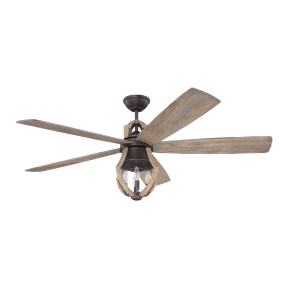
Installation Guide
For Model:
WIN56ABZWP5
E192641
net weight of fan: 0.00 lb (0.00 kg)
READ THESE INSTRUCTIONS AND
SAVE THEM FOR FUTURE USE
Table of Contents:
Safety Tips. pg. 1
Unpacking Your Fan. pg. 2
Parts Inventory. pg. 2
Installation Preparation. pg. 3
Hanging Bracket Installation. pg. 3
Fan Assembly. pgs. 4 - 5
Wiring. pg. 6
Canopy Assembly. pg. 7
Blade Assembly. pg. 7
Light Kit Assembly. pg. 8
Testing Your Fan. pg. 10
Troubleshooting. pg. 11
Warranty. pg. 11
Parts Replacement. pg. 11
PRINTED IN CHINA
Advertisement
Chapters
Table of Contents

Related Manuals for Craftmade WIN56ABZWP5


Summary of Contents for Craftmade WIN56ABZWP5
-
Page 1: Table Of Contents
190W. Therefore, this fan is equipped with a wattage limiting device. Installation Guide For Model: WIN56ABZWP5 Table of Contents: Safety Tips. pg. 1 Unpacking Your Fan. pg. 2 Parts Inventory. pg. 2 Installation Preparation. pg. 3 Hanging Bracket Installation. -
Page 2: Safety Tips
SAFETY TIPS. WARNING: To reduce the risk of electrical shock, turn off the electricity to the fan at the main fuse box or circuit panel before you begin the fan installation or before servicing the fan or installing accessories. READ ALL INSTRUCTIONS AND SAFETY INFORMATION CAREFULLY BEFORE INSTALLING YOUR FAN AND SAVE THESE INSTRUCTIONS. -
Page 3: Unpacking Your Fan
1. Unpacking Your Fan. Carefully open the packaging. Remove items from Styrofoam inserts. Remove motor housing and place on carpet or Styrofoam to avoid damage to finish. Do not discard fan carton or Styrofoam inserts should this fan need to be returned for repairs. -
Page 4: Installation Preparation
3. Installation Preparation. blade edge To prevent personal injury and damage, ensure inches 7 feet that the hanging location allows the blades a (2.13m) (76cm) clearance of 7 feet (2.13m) from the floor and 30in. (76cm) from any wall or obstruction. 12ft. -
Page 5: Fan Assembly. Pgs
5. Fan Assembly. If you wish to extend the hanging length of your fan, you must remove the hanging ball from the set screw set screw hole downrod provided to use with an extended downrod (sold separately). [If you wish to use the stop pin downrod provided, please proceed to instructions following the dotted line below.]... - Page 6 5. Fan Assembly. (cont.) Remove the 2 screws from the edge of the cap at the top of the motor housing. Align holes in yoke cover with holes in cap. Re-insert the 2 screws that were just removed to secure yoke cover.
-
Page 7: Wiring
6. Wiring. white supply wire CAUTION: Be sure outlet box is properly grounded or ground that a ground wire (GREEN or Bare) is present. (green or bare) black supply wire Make sure all electrical connections comply with Local Codes or Ordinances and the National Electrical Code. If you are unfamiliar with electrical wiring or if the from ceiling wire... -
Page 8: Canopy Assembly
7. Canopy Assembly. Locate 2 screws on underside of hanging bracket and hanging bracket remove screw closest to the open end of the hanging bracket. Partially loosen the other screw. Lift canopy to screw hanging bracket. Place rounded part of slotted hole in canopy over loosened screw in hanging bracket and canopy push up. -
Page 9: Light Kit Assembly
9. Light Kit Assembly. motor housing Remove 1 screw from motor plate on underside of motor housing and partially loosen the other 2 screws. Connect WHITE wire from motor housing to WHITE wire from light kit fitter. Connect BLACK wire from motor housing to BLACK wire from light kit fitter. -
Page 10: Automated Learning Process./Activating Code
10. Automated Learning Process./Activating Code. wall control remote control IMPORTANT: Remote and wall controls must be III IV SYNCHRONIZED with fan in order to properly function. IMPORTANT: The code switches in remote and wall controls MUST MATCH ON ECE for fan to function 1 2 3 4 properly. -
Page 11: Testing Your Fan
11. Testing Your Fan. Wall Control It is recommended that you test fan before finalizing installation. Locate ON/OFF slider switch on wall control and set to the ON position. Test light and dimmer function and then test fan speeds. Locate III IV remote control. -
Page 12: Troubleshooting
Return fan, shipping prepaid, to transmitter and wall control are set properly. Craftmade/Ellington. We will repair or ship you a 3. Verify wall control is wired properly. replacement fan, and we will pay the return shipping cost. - Page 13 Por lo tanto, este ventilador tiene un aparato que sirve para limitar el vatiaje. Guía de instalación Para modelo: WIN56ABZWP5 Indice de materias: Sugerencias de seguridad. Pág. 1 Desempaquetado del ventilador. Pág. 2 Inventario de piezas. Pág. 2 Preparación para la instalación. Pág. 3 Instalación del soporte de montaje.
-
Page 14: Sugerencias De Seguridad. Pág
SUGERENCIAS DE SEGURIDAD. ADVERTENCIA: Para evitar la posibilidad de una descarga eléctrica, desconectar la corriente en la caja de fusibles principal o el interruptor protector antes de iniciar la instalación del ventilador o antes de repararlo o instalar accesorios. LEER TODAS LAS INSTRUCCIONES E INFORMACION DE SEGURIDAD CUIDADOSAMENTE ANTES DE INSTALAR SU VENTILADOR Y GUARDAR ESTAS INSTRUCCIONES. -
Page 15: Desempaquetado Del Ventilador. Pág
1. Desempaquetado del ventilador. Abrir el empaque cuidadosamente. Sacar los artículos del embalaje. Sacar el motor y ponerlo en una alfombra o en el embalaje para evitar rayar el acabado. Guardar la caja de cartón o el empaquetamiento original en caso de que tenga que mandar el ventilador para alguna reparación. -
Page 16: Preparación Para La Instalación. Pág
3. Preparación para la instalación. borde del aspa 76cm Para prevenir daño corporal y otros daños, estar seguro de que el lugar en donde va a colgar el ventilador le 2,13m pulg.) permite un espacio libre de 2,13m (7 pies) entre las (7 pies) puntas de las aspas y el piso y 76cm (30 pulg.) entre las aspas y cualquier pared u otra obstrucción. -
Page 17: Ensamblaje Del Ventilador. Págs
5. Ensamblaje del ventilador. agujero para Si usted desea extender la longitud colgante del el tornillo tornillo ventilador, usted tendrá que quitar la bola que sirve para perno de fijación de fijación colgar del tubo provisto para usarla con un tubo más de tope largo (a la venta por separado). - Page 18 5. Ensamblaje del ventilador. (cont.) Quitar los dos tornillos del borde de la tapa en la parte superior del bastidor del motor. Alinear los agujeros en la cubierta del cuello con los agujeros en la tapa. Volver a introducir los 2 tornillos que apenas se quitaron para asegurar la cubierta del cuello.
-
Page 19: Instalación Eléctrica. Pág
6. Instalación eléctrica. PRECAUCION: Asegurarse de que la caja de salida esté alambre conductor blanco toma de tierra conectada a tierra como es debido o que exista un (verde o pelada) conductor a tierra (VERDE o pelado). alambre conductor negro Asegurarse de que toda conexión eléctrica cumpla con los Códigos o las Ordenanzas Locales y el Código Nacional del techo... -
Page 20: Colocación De La Cubierta Decorativa. Pág
7. Colocación de la cubierta decorativa. Localizar los 2 tornillos en la parte inferior del soporte de montaje y quitar el tornillo que está localizado más cerca del extremo abierto del soporte de montaje. Aflojar soporte de montaje parcialmente el otro tornillo. Elevar la cubierta decorativa tornillo hasta el soporte de montaje. -
Page 21: Instalación Del Juego De Luz. Pág
9. Instalación del juego de luz. bastidor Quitar 1 tornillo de la placa del motor en el lado del motor inferior del motor y aflojar los otros 2 tornillos. Conectar el cable BLANCO del conectador para el juego de luz al cable BLANCO del bastidor del motor. - Page 22 10. Proceso de aprendizaje automático./El activar el código. control remoto control de pared IMPORTANTE: Hay que SINCRONIZAR el control remoto y el III IV control de pared con el ventilador para que funcionen correctamente. IMPORTANTE: Usar la MISMA SECUENCIA de números en los conmutadores de las ON ECE unidades de control...
-
Page 23: Verificación Del Funcionamiento Del
11. Verificación del funcionamiento del ventilador. Se le recomienda poner el ventilador a prueba control de pared antes de terminar la instalación. Localizar el interruptor corredero de APAGADO y ENCENDIDO en el control de pared y ponerlo en posición ENCENDIDO. Poner a prueba la luz y el reductor de luz y luego las velocidades del III IV ventilador. - Page 24 Craftmade/Ellington pagará los gastos de envío de regreso. 10 (página 9) que tiene que ver con el botón SET. GARANTIA LIMITADA DE 6 AÑOS hasta DE POR VIDA: CRAFTMADE/ELLINGTON reparará...
Need help?
Do you have a question about the WIN56ABZWP5 and is the answer not in the manual?
Questions and answers