
Related Manuals for Unitech MS912


Summary of Contents for Unitech MS912
- Page 1 Wireless CCD Scanner - MS912 - User's Manual Version 1.2 © 2014 unitech Electronics Co., Ltd. All rights reserved. unitech is a registered trademark of unitech Electronics Co., Ltd.
-
Page 3: Table Of Contents
Table of Contents Chapter 1 Overview......................1 Introducing the MS912...................1 Package Contents ....................2 Scanner Detail......................2 Chapter 2 Installation and Connection ................3 Connecting (Pairing) the Scanner to a Host PC ............3 Power Management .....................12 Charging the Battery ....................13 Chapter 3 Specification .................... - Page 4 Inter-block and Inter-character Delay ..............26 Keyboard Layout ....................27 Caplock Mode, Numeric Key................28 Chapter 5 Wireless Scanner Settings ................29 Interface .......................29 Bluetooth Profile ....................30 Pincode Setup ......................31 Getting Connected - iOS & Android ..............32 Power Off Timeout ....................33 Set Bluetooth Device ID ..................34 Set SPP Pincode ....................35 SPP Master Mode ....................36 SPP Remote Control, Shut Down, Disconnection ..........37...
- Page 5 Interleaved 2 of 5, Code 11 ..................57 Industrial 2 of 5, Matrix 2 of 5 ................59 Codabar .......................61 ABC Codabar, CX Codabar .................63 Codabar Coupling ....................64 Code 39 (Full ASCII/Standard), Code 32 .............65 UPC-E ........................67 UPC-E(0)&(1), UPC-E EXPAND ................68 UPC-A ........................69 EAN-8........................70 EAN-13, ISSN, ISBN, ISMN .................71 EAN/UCC 128, Code 128..................72...
-
Page 7: Chapter 1 Overview
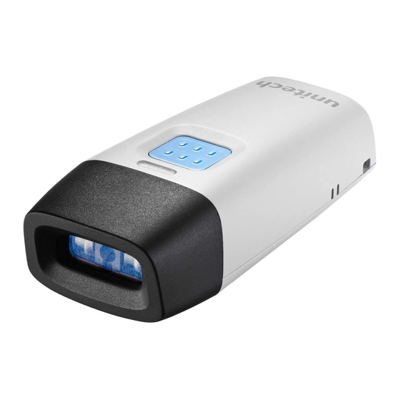
MS912 scanner ensures the productivity and mobility of your business application. The MS912 is the smallest wireless scanners in the market and is compatible with all major OS on the nowadays popular smartphones and tablet PCs via both HID and SPP profiles. -
Page 8: Package Contents
Package Contents Please make sure the following contents are in the MS912 box. If something is missing or damaged, please contact your Unitech representative. MS912 scanner Resource CD Quick Guide USB Charging Cable Hand Strap Quick Connection Card NOTE: 1. The scanner’s default power off (idle mode) time is 3 minutes. -
Page 9: Installation And Connection
Connecting (Pairing) the Scanner to a Host PC Please make sure your PC or Smartphone has a built-in wireless adaptor; the MS912 supports both HID and SPP wireless profiles. If you are connecting it to an iOS (Apple) smartphone, please follow the instruction of “Connecting via Human Interface Device (HID) Mode”;... - Page 10 7. On your host device, in the settings section where you can see Bluetooth settings and manage your connections. a. You will see the MS912 listed as [Wireless Scanner] under Bluetooth devices. b. You will see a message under that [Pair with this device].
- Page 11 If not, please scan [Disconnect] barcode below and repeat steps 1 to 9 above. NOTE: To disconnect the scanner from the host or to switch the wireless profile from one to another, please scan the [Disconnect] barcode: Disconnect After scanning the [Disconnect] barcode, the MS912 will emit 3 beeps.. - 5 -...
- Page 12 Connecting via Human Interface Device (HID) Mode (Non- Pincode) 1. Press the trigger for 1 second to activate the scanner. 2. Scan [DISCONNECT] Disconnect 3. Scan [BT mode - HID non-pincode]; the scanner will emit 8 beeps. BT mode - HID non-pincode 4.
- Page 13 6. Click Wireless Scanner to add to the computer. Then, click Next. 7. In this step, the computer is connecting the wireless scanner. When it connects, click Next. 8. Click Pair without using a code. Then, click Next. - 7 -...
- Page 14 9. Then, click Close. 10. You will see a message telling that the device driver software is installed successfully. 11. The scanner will beep twice to verify the connection. NOTE: In this mode, the scanner is recognized by the host as a mouse (pointing device).
- Page 15 4. Scan the [SPP] barcode below: 5. The scanner will emit several beeps. 6. Conduct a search for the MS912 on your host. Select “Wireless Scanner” from discovered device list and the scanner will beep twice. 7. Enter pincode, which is “1234” by default.
- Page 16 Getting Connected - iOS (Apple) Simply follow instruction in [BT mode - HID]. (page 30), in which step 5 & 6 can be skipped since Apple devices will not require pincode for connection. Touch Keyboard ENABLE iOS HOTKEY DISABLE iOS HOTKEY .
- Page 17 Set Bluetooth Device ID To customize your own Bluetooth device (MS912) name for the wireless scanner, please follow below steps: STEP 1 Scan the Default Wireless ID barcode. .B022$ STEP 2 Scan the Set Wireless ID barcode. .B023$ STEP 3 Scan 7 alphanumeric characters from Full ASCII Chart of Appendix A.
-
Page 18: Power Management
Power Variable Timeout SET MINUTE SET SECOND (Range: 00 ~ 60) (Range: 00 ~ 60) . B030$ . B029$ The timeout is 3 minutes by default, and is programmable to the second and minute, ranging from 10 seconds (00:10) to 60 minutes and 60 seconds (60:60) For example, to set the timeout as 5 minutes 30 seconds: 1. -
Page 19: Charging The Battery
Scanner LED & Beeper Indication Scanner LED & Beeper Indication Green LED Red LED Beeper Remark Power Off or See Power Off Standby Timeout Charging Solid Disconnected or Flash Discoverable Initializing Flash Flash 1 long beep Power Up 1 long beep Barcode scanning w/o proper Flash... - Page 20 - 14 -...
-
Page 21: Chapter 3 Specification
Chapter 3 Specification MS912 Performance/Optical Image Sensor Linear CMOS sensor Light Source 625nm Visible Red LED Max. Resolution 5 mil (0.127mm) Scan Rate 240 scans/second Printing Contrast Scale 30% Minimum Depth of Field Code 39, 5mil: 15mm (near) / 60mm (far) - Page 22 Communication Range 10M (line of sight) Host Interface supported Mini USB Interface/Profile SPP, HID Wireless Class Wireless Class 2 Mechanical Housing Material Dimensions L65 x W24 x H18mm / 2.6 x 0.9 x 0.7in Weight 24.6g / 0.9oz Regulation Approvals FCC Class B, CE Accessories Mini USB cable, Hand Strap, Tools CD...
-
Page 23: Chapter 4 General Settings
Chapter 4 GENERAL SETTINGS Default, Abort, Check Version, Setup Code Read DEFAULT SETUP CODE READ . A001$ . B015$ * Reset to factory default . B016$ CHECK VERSION * Caution: Scanning SETUP CODE . A007$ OFF will turn the scanner into unprogrammable state and the * Check firmware version scanner will not react to any... - Page 24 . F002$ * The LED will light when the trigger is pressed. * The LED will go off when the trigger is released. . F006$ * The LED is always on when the trigger is pressed. * The LED will go off if no bar code has been detected after 60 seconds.
-
Page 25: Beep Tone, Terminator
Beep tone, Terminator BEEP TONE TERMINATOR . D010$ 2.7KHz Buzzer .F01 $ . D011$ . D012$ . D013$ .F021 .F018$ . D014$ .F020$ . D015$ .F022$ . D016$ NOTE: Below is the position of Terminator among output data string: [Preamble] [Symbology ID] [Barcode Length] [Barcode Data] [Postamble] [Terminator] By default, with Preamble, Postamble, Barcode Length and Symbology ID disabled, the scanner data output will be:... -
Page 26: Send Data Length, Preamble, Postamble
Send Data Length, Preamble, Postamble SEND DATA LENGTH PREAMBLE & POSTAMBLE ( PREFIX AND SUFFIX ) .D019$ . A011$ .D020$ . A012$ . A013$ EXAMPLE: Set PREAMBLE String as “ ## ” POSTAMBLE String as “ $$ ” SETTING PROCEDURE: STEP 1 : Scan : CLEAR PRE/ POSTAMBLE. -
Page 27: Accuracy Adjustment
Accuracy Adjustment ACCURACY ADJUSTMENT . A010$ Accuracy Adjustment assures a more reliable decoded output. Enabling the feature and setting a number from 1 to 9 subjects the decoded output a higher standard of accuracy. The higher the number, the greater the accuracy. -
Page 28: Code Id, Inverse Barcode
Code ID, Inverse Barcode ENABLE INVERSE BARCODE .D021$ .D022$ ENABLE CODE ID .A008$ .A014$ .A015$ DISABLE CODE ID .A009$ NOTE: 1. Only ONE code ID will be sent. 2. The code ID is located at the position before the bar code data and after the preamble. -
Page 29: Symbologies Code Identifier
Symbologies Code Identifier SYMBOLOGIES CODE ID IDENTIFIER Factory AIM ID Factory AIM ID Symbologies Symbologies (new) (new) EAN 128 MSI(MOD 10 / CDV & not send CD) Code 128 Code 32 EAN8(+2/+5 OFF) EAN8(+2 ON) Codabar EAN8(+5 ON) Codabar(ABC Codabar) Codabar(CDV &... -
Page 30: Set Code Id
Set Code ID EAN 13 Set ID IATA Set ID . P001$ . P021$ EAN 8 Set ID Code 128 Set ID . P002$ . P010$ UPC E Set ID EAN 128 Set ID . P003$ . P016$ UPC A Set ID Telepen Set ID . - Page 31 Set Code ID MSI Code Set ID Full ASCII Code39 Set ID . P014$ . P008$ UK Plessey Set ID GS1 Databar (RSS) Limited Set ID . P015$ . P019$ Matrix 2 of 5 Set ID GS1 Databar (RSS) Expanded Set ID .
-
Page 32: Inter-Block And Inter-Character Delay
Inter-block and Inter-character Delay INTERBLOCK DELAY INTERCHARACTER DELAY 140uS . B001$ . B010$ 10mS 500uS . B002$ . B011$ 50mS . B003$ . B012$ 100mS . B004$ . B013$ 200mS 16mS . B005$ . B014$ 500mS . B006$ - 26 -... -
Page 33: Keyboard Layout
Keyboard Layout KEYBOARD LAYOUT . C010$ . C021$ . C026$ . C018$ . C024$ . C031$ . C012$ . C016$ . C030$ . C011$ . C023$ . C028$ . C014$ . C009$ . C027$ . C013$ . C025$ . C032$ . -
Page 34: Caplock Mode, Numeric Key
Caplock Mode, Numeric Key CAPITAL LOCK MODE NUMERIC KEY . A004$ . D017$ . A005$ . D018$ . A006$ NOTE: 1. When barcode scanner is set to Caplock Free mode, no matter keyboard Capslock LED indicator is ON or OFF, output will be always the same as the Original barcode. -
Page 35: Wireless Scanner Settings
Chapter 5 WIRELESS SCANNER SETTINGS Interface WIRELESS USB-HID USB-VCP . C035$ . C008$ . C006$ The scanner’s interface Please connect the Please connect the is Wireless by default. scanner with the host scanner with the host with mini USB cable with mini USB cable After scanning above before scanning above... -
Page 36: Bluetooth Profile
(Recommanded) BT mode - SPP BT mode - HID BT mode - HID non-pincode . E042$ . E043$ . E040$ 1. Press the trigger for 1 second to activate 1. Press the trigger for 1. Press the trigger for the scanner. 1 second to activate 1 second to activate the scanner. -
Page 37: Pincode Setup
Pincode Setup STEP 1 Pincode Start . E032$ STEP 2 Scan numeric barcodes (see NUMERIC BARCODES below) based on the pincode generated by the Bluetooth application. NUMERIC BARCODES STEP 3 Enter STEP 4 Pincode Stop . E033$ - 31 -... -
Page 38: Getting Connected - Ios & Android
Getting Connected - iOS & Android Getting Connected - iOS (Apple) Simply follow instruction in [BT mode - HID]. (page 30), in which step 5 & 6 can be skipped since Apple devices will not require pincode for connection. Touch Keyboard ENABLE iOS HOTKEY DISABLE iOS HOTKEY . -
Page 39: Power Off Timeout
Power Off Timeout Variable Timeout SET MINUTE SET SECOND (Range: 00 ~ 60) (Range: 00 ~ 60) . B030$ . B029$ The timeout is 3 minutes by default, and is programmable to the second and minute, ranging from 10 seconds (00:10) to 60 minutes and 60 seconds (60:60) For example, to set the timeout as 5 minutes 30 seconds:... -
Page 40: Set Bluetooth Device Id
Set Bluetooth Device ID To customize your own Bluetooth device name for the wireless scanner, please follow below steps: STEP 1 Default Wireless ID . B022$ STEP 2 Set Wireless ID . B023$ STEP 3 Scan up to 16 alphanumeric characters from Full ASCII Table (page 77-83) as your desired ID name. -
Page 41: Set Spp Pincode
Set SPP Pincode By default, the pincode under SPP profile for the scanner is “1234”. You may customize this pincode with below steps: STEP 1 Set SPP Pincode . B024$ STEP 2 Scan numeric barcodes (see NUMERIC BARCODES below) Up to 8 numbers can be set as SPP pincode. -
Page 42: Spp Master Mode
SPP Master Mode First, please generate one configuration barcode for the target SPP slave device in below methods: 1. The barcode must be Code 39 with no checksum 2. Barcode data format: LTB + Target MAC address For example, the target SPP slave device’s MAC address is 001583522C3B. Please encode: *LTB001583522C3B* in Code39 barcode. -
Page 43: Spp Remote Control, Shut Down, Disconnection
SPP Remote Control, Shut Down, Disconnection SPP REMOTE CONTROL the host under SPP There are two ways to verify connection status by profile. Command Response Host sends: CR,LF,{,A,L,},CR,LF (8 bytes) Scanner replys: O,K,CR,LF (4 bytes) Beeper Response Host sends: CR,LF,{,M,1,},CR,LF (8 bytes) Scanner replys: a short beep... -
Page 44: Batch Mode, Binary Check Character
Batch Mode, Binary Check Character BATCH MODE ENABLE DISABLE . E054$ . E053$ When out of range, the scanner will temporarily keep scanned data in its memory buffer (2K RAM) until the buffer is full. When back in range, the scanner will send all stored data back to the host. NOTE: Batch Mode will not function when Memory Mode is enabled, or no connection is made beforehand. -
Page 45: Memory Mode - Enable Memory, Delete Record
Memory Mode - Enable Memory, Delete Record MEMORY MODE For memory version only ENABLE MEMORY DISABLE MEMORY . R001$ . R002$ Once enabled, the scanner will stop sending data via Bluetooth and start storing data into the internal flash disk (2MB) Delete Last Record/ Clear All Record DELETE LAST RECORD CLEAR ALL RECORD... -
Page 46: Memory Mode - Data Output
Memory Mode - Data Output DATA OUTPUT For memory version only . R003$ OUTPUT DATA Data Output - Interface WIRELESS USB-HID USB-VCP . C035$ . C008$ . C006$ Data Output - Wireless Method To output stored data via WIRELESS, please do the following: 1. - Page 47 Memory Mode - Data Output Data Output - Tethered Method To output stored data via USB-HID please do the following: 1. Connect the scanner and the host with mini USB cable. 2. Scan [USB-HID] 3. Scan [ENABLE MEMORY] (page 39) and scan your desired barcodes. 4.
-
Page 48: Memory Mode - Data Format, Date & Time Setup
Memory Mode - Data Format, Date & Time Setup DATA FORMAT For memory version only . R011$ ENABLE MEMORY The default Data Format is <Item No.>, <Date>, <Time>, <Barcode Data> below are items and their setup codes: Code Item Code Item Item No. - Page 49 Memory Mode - Data Format, Date & Time Setup DATE & TIME SETUP For memory version only . R006$ SET DATE Example: To set Date to 2012-08-01 (Year-Month-Day): 1. Scan [Set Date] 2. Scan [1], [2], [0], [8], [0], [1] from page 83 3.
-
Page 50: Memory Mode - Date Format, Time Format
Memory Mode - Date Format, Time Format DATA FORMAT For memory version only . R008$ DATE FORMAT The default Date Format is DD/MM/YYYY (Code = 09), below is full list of available formats and their setup codes: Code Item Code Item DD-MM-YYYY DD/MM/YYYY... - Page 51 Memory Mode - Date Format, Time Format TIME FORMAT For memory version only . R009$ TIME FORMAT The default Time Format is HH:MM:SS (Code = 01), below are available formats and their setup codes: Code Item Code Item HH:MM:SS HH:MM Example: To set Time Format to HH:MM (Code = 02) 1.
-
Page 52: Memory Mode - Quantity
Memory Mode - Quantity QUANTITY For memory version only . R017$ ENABLE QUANTITY INPUT Once you enable quantity input, the operation procedure under memory mode will be as follows: 1. Scan [ENABLE MEMORY] (page 39) 2. Set DATA FORMAT (page 42-43) as appropriate. For example, your data format is <Barcode Data>, <Quantity>. - Page 53 . R018$ DISABLE QUANTITY INPUT Once quantity input is diabled, the operation procedure under memory mode will be as follows: 1. Scan [ENABLE MEMORY] (page 39) 2. Set DATA FORMAT (page 42-43) as appropriate. For example, your data format is <Barcode Data>, <Quantity>. 3.
- Page 54 - 48 -...
-
Page 55: Chapter 6 Symbologies
Chapter 6 SYMBOLOGIES Enable/Disable Barcode Symbology ENABLE DISABLE . A002$ . A003$ . K010$ . K011$ . K001$ . K002$ . L010$ . L011$ . N001$ . N002$ . M010$ . M011$ . J001$ . J002$ . J010$ . J011$ . - Page 56 Enable/Disable Barcode Symbology ENABLE DISABLE . H001$ . H002$ . H007$ . H008$ . H019$ . H020$ . H013$ . H014$ . L001$ . L002$ . G008$ . G009$ . I 010$ . I 011$ . G010$ . G011$ . M001$ .
-
Page 57: China Postcode (Toshiba Code)
Enable/Disable Barcode Symbology ENABLE DISABLE . N032$ . N033$ . N038$ . N039$ . N010$ . N011$ . N026$ . N027$ . N028$ . N029$ . G021$ . G022$ China postcode (Toshiba code) . K001$ . K004$ . K002$ . K005$ . -
Page 58: Setting Procedure
APPENDIX FULL ASCII ( Code 39 ) NUMERIC TABLE SETTING PROCEDURE: MIN / MAX LENGTH STEP 1 - Scan: MIN LENGTH/ MAX LENGTH STEP 2 - Scan: Two digits from Appendix. STEP 3 - Scan: MIN LENGTH/ MAX LENGTH Please note that when Min Length and / or Max Length are enabled, the scanner will only read bar codes that fall into those length parameters. -
Page 59: Msi Code, Uk Plessey Code
MSI code, UK Plessey code UK PLESSEY CODE . L001$ . L010$ . L002$ . L011$ . L004$ . L012$ . L003$ . L013$ . L007$ . L008$ . L009$ . L005$ . L006$ - 53 -... - Page 60 APPENDIX FULL ASCII ( Code 39 ) NUMERIC TABLE SETTING PROCEDURE: MIN / MAX LENGTH STEP 1 - Scan: MIN LENGTH/ MAX LENGTH STEP 2 - Scan: Two digits from Appendix. STEP 3 - Scan: MIN LENGTH/ MAX LENGTH Please note that when Min Length and / or Max Length areenabled, the scanner will only read bar codes that fall intothose length parameters.
-
Page 61: Code 93, Telepen, Iata
Code 93, Telepen, IATA CODE 93 TELEPEN IATA . G010$ . L014$ . N017$ . G011$ . L015$ . N018$ . G012$ . L020$ . N019$ . G013$ . L021$ . N020$ . N021$ . N022$ . N023$ - 55 -... - Page 62 APPENDIX FULL ASCII ( Code 39 ) NUMERIC TABLE SETTING PROCEDURE: MIN / MAX LENGTH STEP 1 - Scan: MIN LENGTH/ MAX LENGTH STEP 2 - Scan: Two digits from Appendix. STEP 3 - Scan: MIN LENGTH/ MAX LENGTH Please note that when Min Length and / or Max Length areenabled, the scanner will only read bar codes that fall intothose length parameters.
-
Page 63: Interleaved 2 Of 5, Code 11
Interleaved 2 of 5, Code 11 INTERLEAVED 2 OF 5 CODE 11 . J001$ . I 010$ . J002$ . I 011$ . J003$ . I 012$ . J004$ . I 013$ . J005$ . I 042$ . J008$ . I 043$ . - Page 64 APPENDIX FULL ASCII ( Code 39 ) NUMERIC TABLE SETTING PROCEDURE: MIN / MAX LENGTH STEP 1 - Scan: MIN LENGTH/ MAX LENGTH STEP 2 - Scan: Two digits from Appendix. STEP 3 - Scan: MIN LENGTH/ MAX LENGTH Please note that when Min Length and / or Max Length areenabled, the scanner will only read bar codes that fall intothose length parameters.
-
Page 65: Industrial 2 Of 5, Matrix 2 Of 5
Industrial 2 of 5, Matrix 2 of 5 INDUSTRIAL 2 OF 5 MATRIX 2 OF 5 . N001$ . M010$ . N002$ . M011$ . N003$ . M012$ . N004$ . M013$ . N005$ . M014$ . N006$ . M015$ . - Page 66 APPENDIX FULL ASCII ( Code 39 ) NUMERIC TABLE SETTING PROCEDURE: MIN / MAX LENGTH STEP 1 - Scan: MIN LENGTH/ MAX LENGTH STEP 2 - Scan: Two digits from Appendix. STEP 3 - Scan: MIN LENGTH/ MAX LENGTH Please note that when Min Length and / or Max Length areenabled, the scanner will only read bar codes that fall intothose length parameters.
-
Page 67: Codabar
Codabar CODABAR START / STOP CLSI FORMAT . I 001$ . I 030$ CLSI- Enable library space insertion. If you enable the CLSI format, this option inserts spaces in position 2, 7, 13 of the data string for use in library systems. - Page 68 APPENDIX FULL ASCII ( Code 39 ) NUMERIC TABLE SETTING PROCEDURE: MIN / MAX LENGTH STEP 1 - Scan: MIN LENGTH/ MAX LENGTH STEP 2 - Scan: Two digits from Appendix. STEP 3 - Scan: MIN LENGTH/ MAX LENGTH Please note that when Min Length and / or Max Length areenabled, the scanner will only read bar codes that fall intothose length parameters.
-
Page 69: 43 Abc Codabar, Cx Codabar
43 ABC Codabar, CX Codabar ABC- CODABAR CX CODE- CODABAR . I 017$ . I 022$ . I 018$ . I 023$ . I 035$ . I 037$ . I 039$ . I 040$ . I 036$ . I 038$ * The data can be any * The data can be any alphanumerics alphanumerics of FULL ASCII... -
Page 70: Codabar Coupling
Codabar Coupling CODABAR COUPLING . I 019$ . I 020$ . I 021$ . I 041$ . I 026$ ABC-Codabar and CX-Codabar have certain rules regarding the Stop Character of first bar code and the stop character of second bar code while in conjunction, while Codabar- Coupling is enabled, the data from any two Codabar bar codes can be coupled into one set of data without any limitations between the Stop character of first bar code and the Start character of second bar... -
Page 71: Code 39 (Full Ascii/Standard), Code 32
Code 39 (Full ASCII/Standard), Code 32 STANDARD CODE 39 & FULL ASCII 39 . G008$ . G009$ . G001$ . G002$ . G014$ . G003$ . G004$ . G005$ . G006$ . G007$ . G015$ NOTE: The default for Code 39 is Standard Code 39. If Full ASCII Code 39 is enabled, Standard Code 39 will be automatically disabled. - Page 72 APPENDIX FULL ASCII ( Code 39 ) NUMERIC TABLE SETTING PROCEDURE: MIN / MAX LENGTH STEP 1 - Scan: MIN LENGTH/ MAX LENGTH STEP 2 - Scan: Two digits from Appendix. STEP 3 - Scan: MIN LENGTH/ MAX LENGTH Please note that when Min Length and / or Max Length areenabled, the scanner will only read bar codes that fall intothose length parameters.
-
Page 73: Upc-E
UPC-E UPC-E . H007$ . H008$ . H009$ . H010$ . H011$ . H012$ ADD ON SUPPLEMENT . H037$ . H038$ . H039$ . H040$ . H047$ . H048$ . H056$ . H055$ NOTE: If ADDENDA REQUIRED is set to ON, the scanner will only read an UPC-E bar code that has an addenda. -
Page 74: Upc-E(0)&(1), Upc-E Expand
UPC-E(0)&(1), UPC-E EXPAND UPC-E0 . H064$ . H063$ UPC-E1 . H065$ . H066$ NOTE: Most UPC bar codes lead with 0 number systems, for these bar codes use UPC E(0) selection. For the bar codes that lead with the 1 number, use UPC E(1) selection. -
Page 75: Upc-A
UPC-A UPC- A . H001$ . H002$ . H003$ . H004$ . H005$ . H006$ UPC-A EXPANDTO EAN-13 . H068$ . H067$ ADD ON SUPPLEMENT . H033$ . H034$ . H035$ . H036$ . H045$ . H046$ . H060$ . H059$ NOTE: If ADDENDA REQUIRED is set to ON, the scanner will only read an UPC-E bar code that has an addenda. -
Page 76: Ean-8
EAN-8 EAN-8 . H019$ . H020$ . H021$ . H022$ . H023$ . H024$ ADD ON SUPPLEMENT . H029$ . H030$ . H031$ . H032$ . H043$ . H044$ . H062$ . H061$ NOTE: If ADDENDA REQUIRED is set to ON, the scannerwill only read an UPC-E bar code that has an addenda.At the same time please also scan +5 ON or +2 ON sothe scanner will output a 5-digit or 2-digit addendum. -
Page 77: Ean-13, Issn, Isbn, Ismn
EAN-13, ISSN, ISBN, ISMN EAN-13 . H013$ . H014$ . H015$ . H016$ . H017$ . H018$ ADD ON SUPPLEMENT . H025$ . H026$ . H027$ . H028$ . H041$ . H042$ . H058$ . H057$ ISBN . H050$ . H049$ NOTE: 1. -
Page 78: Ean/Ucc 128, Code 128
EAN/UCC 128, Code 128 EAN/ UCC-128 . M001$ . M002$ . M003$ . M004$ . M005$ . M006$ . M007$ NOTE: DEFINE EAN 128 IThe first FNC1 character is translated to ]c1, and the second FNC1 character is translated to an ASCII <GS> character (scan from page 75-86) String format: DATA CHARACTERS <GS>... -
Page 79: Databar(Rss) Stacked, Limited, Expanded
DataBar(RSS) Stacked, Limited, Expanded GS1 DataBar (RSS) - OMNI & STACKED . N032$ . N034$ . N036$ . N038$ . P024$ . N033$ . N035$ . N037$ . N039$ GS1 DataBar (RSS) - LIMITED . N010$ . N012$ . N024$ . - Page 80 - 74 -...
-
Page 81: Chapter 7 Symbologies
Chapter 7 SYMBOLOGIES Full ASCII table(Code 39) CONTROL CODES - 75 -... - Page 82 Full ASCII table(Code 39) CONTROL CODES - 76 -...
- Page 83 Full ASCII table(Code 39) SYMBOLS · · & - 77 -...
- Page 84 Full ASCII table(Code 39) SYMBOLS " < > - 78 -...
- Page 85 Full ASCII table(Code 39) UPPER CASE ALPHABETS - 79 -...
- Page 86 Full ASCII table(Code 39) UPPER CASE ALPHABETS - 80 -...
- Page 87 Full ASCII table(Code 39) LOWER CASE ALPHABETS - 81 -...
- Page 88 Full ASCII table(Code 39) LOWER CASE ALPHABETS - 82 -...
- Page 89 Full ASCII table(Code 39) NUMBERS - 83 -...
-
Page 90: Function Key Table(Code 39) For Pc-At
Function Key table(Code 39) for PC-AT FUNCTION KEYS Home Enter $T+D (Numeric Key) $T+O - 84 -... - Page 91 62-64 NAVIGATION KEYS Cursor Right Back Tab Cursor Left Enter Cursor Up Cursor Down Page Up Page Down $T%K - 85 -...
- Page 92 Function Key table(Code 39) for PC-AT MODIFIER KEYS $T%L $T%M $T+E $T+F $T%N $T%O $T+I $T+J $T+K $T+L $T+M $T+N $T%W $T+A $T+G $T+H For UK Keyboard Special Character $T+B $T+C NOTE: *1: When “Alt(Left)Make” is programmed, please scan “Alt(Left)Break” to resume barcode setting..
-
Page 93: Trouble Shooting
Trouble Shooting Our Barcode Scanners are simple to install and use. Most operational issues can be attributed to: INCORRECT INTERFACE CONNECTION INCORRECT CONFIGURATION SETUP POOR BARCODE QUALITY GENERAL PROCEDURES 1. First, make sure the scanner is firmly connected to the host computer, when attached correctly, the scanner will emit one long beep. - Page 94 Does keyboard port supply enough power? Most notebook computers do not supply enough power to the scanner. The symptom of insufficient power is a lower “good read” rate (since there is not enough power to properly support the scanning operation). RS232 INTERFACE PROBLEMS Once you read bar code, there is no output on the monitor, the symptoms may be caused by:...
- Page 95 CONFIGURATION SETUP Are you set up for the right Interface? Are you set up for the right interface? Did you select the Keyboard Wedge cable but set the scanner for RS-232 or Wand Emulation? Or did you change the Keyboard cable to RS-232 but forget to set the scanner interface to RS-232 as well? Set the scanner to its default settings, then select the correct interface based upon the cable and input you are using.
- Page 96 LABELS (PAPER & COLOR & PRINTER) The light source of a bar code scanner is generally red, so there are some restrictions for the printing of labels. Care should be taken when choosing materials, especially color inks and papers. Sometimes the combination of the label color and the color of the ink can, in effect, blind the scanner.
-
Page 97: Appendix I Default Table
Appendix I Default table GROUP PARAMETER DEFAULT Computer Type PC-AT Interface (depends on customer order) Setup Code Reading Mode Trigger Bi-color Light Source Green > Red Magnetic Switch Green LED/ Supplement Light (CCD Scanner) Deactivation Time (CCD & Laser Scanner) 3 Sec Same Code Interval (Laser Scanner) 30 Sec Idle Mode... - Page 98 GROUP PARAMETER DEFAULT Beep Tone Mode 2.1k Beep Medium Beep Tone Mode 2.7k Beep Medium CR(KB, USB); CR+LF Terminator (RS232) Send Data Length Preamble & Postamble None Accuracy Adjustment Label Type Positive/ Negative Disable Enable & Disable Code ID Interblock Delay Intercharacter Delay 140us Keyboard Layout...
- Page 99 GROUP PARAMETER DEFAULT UPC-A Enable UPC-E Enable EAN-8 Enable EAN-13 Enable Disable Code 39 Enable Code 11 Disable Code 93 Disable EAN-128 Enable IATA Disable GS1 Databar Disable GS1 Databar Stacked Enable GS1 Databar Limited Disable GS1 Databar Expanded Disable GS1 Databar Expanded Stacked Enable PDF417...
- Page 100 GROUP PARAMETER DEFAULT Code 93 Enable/Disable Disable Min Length 6 digits Max Length 48 digits Telepen Enable/Disable Disable Telepen ASCII/ Number Number IATA Enable/Disable Disable Check Digits Disable CDV Min Length 6 digits Max Length 48 digits Interleaved 2 of 5 Enable/Disable Enable Check Digits...
- Page 101 GROUP PARAMETER DEFAULT Codabar Enable/Disable Disable Check Digits Disable CDV Min Length 6 digits Max Length 48digits ST/SP; Abcd/abcd, abcd/tn*c, ABCD/ABCD ABCD/ABCD,ABCD/TN*C Start(ST)/Stop(SP) Send CLSI Format ABC-Codabar ON/OFF Insert Data CX-Codabar ON/OFF Insert Data Codabar-Coupling ON/OFF Insert Data Adjacent Required Code 39 Full ASCII 39 Enable/Disable Enable...
- Page 102 GROUP PARAMETER DEFAULT UPC-E Enable/Disable Enable Check Digits Send Lead Digits Send Add a space Addenda required +5 On/Off +2 On/Off UPC-E systems number UPC E(0) On/Off UPC E(1) On/Off UPC-E expand to UPC-A Disable UPC-A expand to EAN-13 Disable UPC-A Enable/Disable Enable...
- Page 103 GROUP PARAMETER DEFAULT EAN-13 Enable/Disable Enable Check Digits Send Lead Digits Send Add a space Addenda required +5 On/Off +2 On/Off ISSN On/Off ISBN EAN/UCC128 Enable/Disable Enable Code ID Disable Func 1 Char Send Not Send Code128 Enable/Disable Enable Check Digits Disable CDV Min Length 5 digits...
- Page 104 - 98 -...
-
Page 105: Appendix Ii
Appendix II Cable Pin Assignment INTERFACES: 1. TTL, Wand Emulation 1.1 ) AMP (D-Sub 9Pin): 1.2 ) Din 5 male (240 degree): Signal Signal Data +5VCC Data +5VCC 2. Keyboard Interface: Din6 Female: 2.1 ) PS/2 Mini Din6 Female: 2.2 ) PS/2 Mini Din6 Male: Signal Signal PC Data... - Page 106 2. Keyboard Interface: Din6 Female: 2.3) PC-AT: Din 5 Male: 2.4) PC-AT: Din 5 Female: Signal Signal KB-Clk PC-Clk KB-Data PC-Data +5VCC +5VCC 3. RS232 Interfaces: 3.1) DB9F 3.2) DB25F Signal Signal TXD(Out) RXD(In) RXD(In) TXD(Out) CTS(In) CTS(In) RTS(Out) RTS(Out) +5VCC +5VCC +5VCC...
-
Page 107: Appendix Ii
Appendix II Barcode test chart NARROW WIDE CHAR.GAP DENSITY mm[mil] mm[mil] mm[mil] RATIO MEDIUM 0.25(10) 0.625(25) 0.25(10) 1/2.5 DENSITY MEDIUM DENSITY NW-7 [CODABAR] CODE-39 Interleaved 2of5 - 101 -... - Page 108 NARROW WIDE CHAR.GAP DENSITY mm[mil] mm[mil] mm[mil] RATIO MEDIUM 0.25(10) 0.625(25) 0.25(10) 1/2.5 DENSITY LOW DENSITY - 102 -...
-
Page 109: Appendix Iv Worldwide Support
Appendix IV Worldwide Support Unitech’s professional support team is available to quickly answer questions or technical-related issues. Should an equipment problem occur, please contact the nearest Unitech regional service representative. For complete contact information please visit the Web sites listed below:...
Need help?
Do you have a question about the MS912 and is the answer not in the manual?
Questions and answers