Table of Contents
Advertisement
Available languages
Available languages
Speed Scrub
Model No.:
608622
608623 – Pac
609243 – Can. Pac
NOBLES
12875 RANSOM STREET
HOLLAND MI 49424 U.S.A.
CUSTOMER SERVICE: 1-800-365-6625
FAX: 1–800–678–4240
Home Find... Go To..
ENGLISH - ESPAÑOL
t
2001
Battery Automatic Scrubber
Fregadora Automática Batería
Operator and Parts Manual
Manual de Operación y de Piezas
608624
Rev. 01 (11-01)
Advertisement
Chapters
Table of Contents

Related Manuals for Nobles 608622


Summary of Contents for Nobles 608622
- Page 1 Speed Scrub 2001 Battery Automatic Scrubber Fregadora Automática Batería Operator and Parts Manual Model No.: Manual de Operación y de Piezas 608622 608623 – Pac 609243 – Can. Pac NOBLES 12875 RANSOM STREET HOLLAND MI 49424 U.S.A. 608624 CUSTOMER SERVICE: 1-800-365-6625 FAX: 1–800–678–4240...
-
Page 2: Table Of Contents
Specifications and parts are subject to change without notice. This machine will provide excellent service. However, the best results will be obtained at minimum costs if: Nobles and Speed Scrub are registered United States trademarks of Tennant Company. The machine is operated with reasonable care. -
Page 3: Safety Precautions
OPERATION 5. When servicing machine: SAFETY PRECAUTIONS – Avoid moving parts. Do not wear loose jackets, shirts, or sleeves. – Block machine tires before jacking This machine is intended for commercial use. It is machine up. suited to scrub floors in an indoor environment and is –... -
Page 4: Machine Components
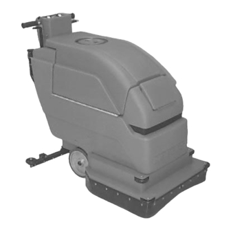
OPERATION MACHINE COMPONENTS 1. Control Grips 12. Recovery Tank Drain Hose 2. Vacuum ON/OFF Switch 13. Solution Tank Drain Hose 3. Brush ON/OFF Switch 14. Squeegee Assembly 4. Battery Meter 15. Control Console 5. Brush Circuit Breaker 16. Recovery Tank 6. -
Page 5: Machine Installation
OPERATION MACHINE INSTALLATION UNCRATING MACHINE Carefully check carton for signs of damage. Report damages at once to carrier. Check carton contents to ensure all accessories are included. To uncrate your machine, remove straps and raise brush head. To raise brush head, step down firmly on the bottom brush lift foot pedal until pedal locks into the raised position. -
Page 6: Machine Setup
OPERATION MACHINE SETUP PRE–OPERATION CHECKS 1. Sweep and dust mop floor. 2. Check battery meter charge level to ensure batteries are fully charged (See BATTERY CHARGING). 3. Check that a pad/brush is installed. FIG. 4 4. Check that squeegee is installed. 3. -
Page 7: Filling Solution Tank
OPERATION 3. Open solution fill door at front of machine and fill solution tank with 38L (10 gal) of clean water, 60°C (140°F) maximum temperature. Or use the rear fill port to fill solution tank. The clear tube below the fill port has 19L (5 gal) increment markers to indicate amount of water in tank (Figure 9). -
Page 8: Machine Operation
OPERATION MACHINE OPERATION FOR SAFETY: Do not operate machine unless operator manual is read and understood. 1. Adjust control grips to a comfortable operating height (three settings). Squeeze together two levers under console to raise or lower control grips (Figure 10). FIG. -
Page 9: While Operating Machine
OPERATION 6. Turn brush switch to the on position. 6. Periodically check battery meter’s discharge level. When needle drops to the red zone, recharge ATTENTION: To prevent floor finish damage, DO batteries. NOT leave machine at stand still once brush begins to spin. -
Page 10: Draining Tanks
OPERATION 2. Clean recovery tank after each use. Use a hose to rinse out recovery tank. Be careful not to spray DRAINING TANKS water into float shut-off screen. 3. Replace drain hose plug tightly after draining. 1. Turn machine off. FOR SAFETY: Before leaving or servicing DRAINING SOLUTION TANK machine, stop on level surface and turn off... -
Page 11: Battery Charging
OPERATION BATTERY CHARGING NOTE: Recharge batteries ONLY after a total of 30 minutes of use or more. This will prolong battery life. The following charging instructions are intended for chargers supplied with machine. Only use a charger with the following specifications to FIG. -
Page 12: Machine Maintenance
OPERATION WEEKLY MAINTENANCE MACHINE MAINTENANCE (Every 20 Hours of Use) 1. Check fluid level in battery cells. To keep machine in good working condition, simply 2. Clean battery tops from corrosion. follow machines daily, weekly and monthly maintenance procedures. 3. Check for loose or corroded battery cables. FOR SAFETY: Before leaving or servicing machine, stop on level surface and turn off MONTHLY MAINTENANCE... -
Page 13: Transporting Machine
OPERATION STORING MACHINE Store machine in a dry area in the upright position. Before storing machine be certain to flush tanks and drain machine of all water. Remove recovery tank lid to promote air circulation. Raise pad driver and squeegee off floor to prevent damage. ATTENTION If storing machine in freezing FIG. -
Page 14: Trouble Shooting
OPERATION TROUBLE SHOOTING PROBLEM CAUSE SOLUTION No power. Batteries need charging. See Battery Charging. Battery(s) faulty. Replace battery(s) Loose battery cable. Tighten loose cables. Batteries are not connected See Battery Installation. correctly. Brush motor does not run. Faulty brush switch. Contact Service Center. - Page 15 OPERATION TROUBLE SHOOTING – CONTINUED PROBLEM CAUSE SOLUTION Poor water pick up. Recovery tank is full. Empty recovery tank. Ball float shutoff screen inside Remove screen and clean. recovery tank is clogged. Squeegee is clogged with debris. Clean squeegee. Squeegee blades are worn. Replace squeegee blades.
-
Page 16: Specifications
OPERATION SPECIFICATIONS LENGTH 1194 mm (47 in) WIDTH 559 mm (22 in) HEIGHT 965 mm (38 in) WEIGHT 146 Kg (315 lb) SOLUTION TANK CAPACITY 38 L (10 gal) RECOVERY TANK CAPACITY 45 L (12 gal) CLEANING PATH WIDTH 508 mm (20 in) BRUSH MOTOR .75hp, 220 rpm, 24v, 20A, 560w VACUUM MOTOR... - Page 17 OPERACIÓN Este manual acompaña a todos los modelos estándar nuevos. En él se indican las instrucciones necesarias DATOS DE LA MÁQUINA para la utilización y el mantenimiento de la máquina. Lea el manual entero para comprender el Sírvase llenar los datos en el momento de la preparación funcionamiento de la máquina antes de utilizarla o para referencia en el futuro.
-
Page 18: Medidas De Seguridad
OPERACIÓN 4. Antes de estacionar o revisar la máquina: MEDIDAS DE SEGURIDAD – Deténgase en una superficie plana. – Apague la máquina. 5. Al revisar la máquina: Esta máquina está destinada al uso comercial. Está – Evite las partes en movimiento. No lleve diseñada para fregar suelos en recintos cerrados y no chaquetas, camisas o mangas sueltas. -
Page 19: Componentes De La Máquina
OPERACIÓN COMPONENTES DE LA MÁQUINA 1. Mandos de control 12. Manguera de vaciado del depósito de recuperación 2. Interruptor de Encendido/Apagado (ON/OFF) de la aspiración 13. Manguera de vaciado del depósito de recuperación con indicación en galones. 3. Interruptor de Encendido/Apagado (ON/OFF) del cepillo 14. -
Page 20: Instalación De La Máquina
OPERACIÓN INSTALACIÓN DE LA MÁQUINA DESEMBALADO DE LA MÁQUINA Compruebe cuidadosamente si la caja de cartón muestra daños. En caso de que así sea informe inmediatamente de los daños al transportista. Controle el contenido de la caja para asegurarse que incluye todos los accesorios. -
Page 21: Preparación De La Máquina
OPERACIÓN PREPARACIÓN DE LA MÁQUINA COMPROBACIONES PREVIAS A LA PUESTA EN FUNCIONAMIENTO 1. Barra el suelo para eliminar partículas y otros restos. 2. Controle el nivel de carga de la batería para asegurarse que de las baterías estén completamente cargadas en caso necesario FIG. -
Page 22: Llenado Del Depósito De La Disolución
OPERACIÓN 6. Conecte el impulsor del cepillo o de la almohadilla al cubo del motor. Alinee los tres pernos de montaje con las ranuras del cubo del motor. Gire rápidamente el impulsor hacia el sujetador de resorte del cubo del motor. Asegúrese de que el impulsor de la almohadilla está... -
Page 23: Funcionamiento De La Máquina
OPERACIÓN 4. Coloque el interruptor de aspiración en la posición de encendido (ON). FUNCIONAMIENTO DE LA MÁQUINA 5. Empuje la palanca del flujo de la disolución ligeramente hacia delante para activar el paso de PARA PROTECCION: No opere la máquina a la disolución. -
Page 24: Durante La Utilización De La Máquina
OPERACIÓN 8. Cuando se vacíe el depósito de la disolución, coloque el interruptor del cepillo en la posición de DURANTE LA UTILIZACIÓN DE LA MÁQUINA apagado (OFF), cierre el flujo de la disolución 1. Compruebe periódicamente que no exista mediante la palanca del flujo de la disolución y acumulación de espuma en el depósito de continúe aspirando hasta que todo el agua sucia recuperación (mire a través de la tapa... -
Page 25: Vaciado Del Depósito De La Disolución
OPERACIÓN 1. Retire la manguera de vaciado de su soporte, 3. Empuje la palanca del flujo de la disolución hacia coloque la manguera en el desagüe del suelo y delante para aclarar el sistema de flujo de la desenrosque el tapón de la manguera de vaciado. disolución. - Page 26 OPERACIÓN FIG. 18 FIG. 20 ADVERTENCIA: Las baterías emiten NOTA: Una vez conectado el cargador a la máquina, hidrógeno gaseoso. Existe peligro de incendio o la máquina no funcionará. explosión. Mantenga chispas y llamas alejadas de 6. Enchufe el cable eléctrico del cargador a un la máquina.
-
Page 27: Mantenimiento De La Máquina
OPERACIÓN MANTENIMIENTO SEMANAL MANTENIMIENTO DE LA MÁQUINA 1. Aclare los depósitos y el sistema de tuberías de la disolución. Haga una disolución con 946 ml de Para mantener la máquina en buenas condiciones de vinagre y 11,3 litros de agua. Aclare funcionamiento bastará... -
Page 28: Transporte De La Máquina
OPERACIÓN ALMACENAMIENTO DE LA MÁQUINA Guarde la máquina en un sitio seco en posición vertical. Antes de guardar la máquina asegúrese de limpiar los depósitos y vaciar el agua de la máquina. Retire la tapa del depósito de recuperación para facilitar la circulación de aire. -
Page 29: Localización De Averías
OPERACIÓN LOCALIZACIÓN DE AVERÍAS PROBLEMA CAUSA SOLUCIÓN No hay alimentación, no Las baterías necesitan ser cargadas. Consultar el apartado de CARGA DE funciona nada. LAS BATERÍAS. Batería(s) defectuosa(s). Sustituir las baterías. Cable de la batería flojo. Apretar los cables flojos. Las baterías están mal conectadas. - Page 30 OPERACIÓN LOCALIZACIÓN DE AVERÍAS – continuación PROBLEMA CAUSA SOLUCIÓN Funcionamiento defectuoso Depósito de recuperación lleno. Vaciar el depósito de recuperación. de las escobilla de goma Filtro del flotador de cierre del depósito Extraer el filtro y limpiarlo. de recuperación obstruido. Escobilla de goma bloqueada por restos.
-
Page 31: Especificaciones
OPERACIÓN ESPECIFICACIONES MODELO Speed Scrubt 2001 LONGITUD 1194 mm (47 in) ANCHURA 559 mm (22 in) ALTURA 965 mm (38 in) PESO 146 Kg (315 lb) CAPACIDAD DEL DEPÓSITO DE LA DISOLUCIÓN 38 L (10 gal) CAPACIDAD DEL DEPÓSITO DE RECUPERACIÓN 45 L (12 gal) ANCHURA DEL CARRIL DE LIMPIEZA 508 mm (20 in) -
Page 32: Electrical Diagrams
ELECTRICAL DIAGRAMS DIAGRAMAS ELECTRICAS BATTERY METER 24V WIRE DIAGRAM VACUUM BRUSH SWITCH SWITCH RED 14 RED 18 RED 18 BLK 18 SOLENOID BLK 16 RED 18 RED 8 RED 10 RED 10 35 AMP BREAKER RED 14 SWITCH RED 8 RED 8 CHARGER PLUG... - Page 33 ELECTRICAL DIAGRAMS DIAGRAMAS ELECTRICAS CHARGER 24V LADDER PLUG DIAGRAM VACUUM SWITCH VACUUM MOTOR BATTERY METER SAFETY LIGHTS BRUSH SWITCH BRUSH MOTOR SOLENOID 35 AMP BREAKER SWITCH Speed Scrubt 2001 Battery (11–01) Home Find... Go To..
-
Page 34: Parts List
PARTS LIST LISTA DE PIEZAS REPLACEMENT BRUSHES AND PAD DRIVER GROUP CEPILLO DEL REEMPLAZO Y GRUPO DEL MANDO DE LA ALMOHADILLA Speed Scrubt 2001 Battery (11–01) Home Find... Go To.. - Page 35 PARTS LIST LISTA DE PIEZAS REPLACEMENT BRUSHES AND PAD DRIVER GROUP CEPILLO DEL REEMPLAZO Y GRUPO DEL MANDO DE LA ALMOHADILLA PART # DESCRIPTION QTY. PART # DESCRIPTION QTY. ∇ DBRUSH, POLY–SCRUB ∇ DPAD DRIVER ASM 20” 240250 240249 DBRUSH, DYNA–SCRUB DLUGS, W/SCREWS (SET OF 3) 240251 240254...
-
Page 36: Solution Tank Group
PARTS LIST LISTA DE PIEZAS SOLUTION TANK GROUP GRUPE DEL DEPÓSITO DE DISOLUCIÓN Speed Scrubt 2001 Battery (11–01) Home Find... Go To.. - Page 37 CLAMP, HOSE 2WIRE BLK 140706 RIVET, POP 1/8 608455 DECAL, SPEED SCRUB 2001 SIDE 608627 TANK, SOLUTION GREEN 608185 DECAL, NOBLES 6.75” LOGO DSCREEN, SOLUTION FILL 607099 150419 FITTING, 1/4MX3/8H ELB 90 3701.6 SCREW, #6X3/8 607775 CLAMP, HOSE 2WIRE BLK DHOSE, 3/8IDX5/8ODX10.25...
-
Page 38: Solution Tank Rear Panel Group
PARTS LIST LISTA DE PIEZAS SOLUTION TANK REAR PANEL GROUP CONJUNTO PANEL TRASERA Speed Scrubt 2001 Battery (11–01) Home Find... Go To.. - Page 39 PARTS LIST LISTA DE PIEZAS SOLUTION TANK REAR PANEL GROUP CONJUNTO PANEL TRASERA PART # DESCRIPTION QTY. PART # DESCRIPTION QTY. DGASKET, TUBE–ADAPTER 100151 140226 SCREW, 5/16–18X5/8 230664 ADAPTER, TUBE 140548 NUT, 5/16 FINJAM 140424 SPRING, TUBE–ADAPTER 240191 KNOB, 5/16–18X2” 230873 MOUNT, PLATE WELDMENT 140259...
-
Page 40: Recovery Tank Group
PARTS LIST LISTA DE PIEZAS RECOVERY TANK GROUP CONJUNTO DESPÓSITO RECUPERAR 37 34 Speed Scrubt 2001 Battery (11–01) Home Find... Go To.. - Page 41 PARTS LIST LISTA DE PIEZAS RECOVERY TANK GROUP CONJUNTO DESPÓSITO RECUPERAR PART # DESCRIPTION QTY. PART # DESCRIPTION QTY. ∇ 701103 ASM, STANDPIPE W/NIPPLE 140259 SCREW, 1/4–20X5/8 606088 FITTING, 1–1/2” NIPPLE 140016 WASHER, 1/4 LOCK DGASKET, WASTE AIR CHAMBER 101714 140000 WASHER, 1/4 FLAT DCABLE, REC.
-
Page 42: Control Console Group
PARTS LIST LISTA DE PIEZAS CONTROL CONSOLE GROUP CONJUNTO CONSOLA DE CONTROLES Speed Scrubt 2001 Battery (11–01) Home Find... Go To.. - Page 43 PARTS LIST LISTA DE PIEZAS CONTROL CONSOLE GROUP CONJUNTO CONSOLA DE CONTROLES PART # DESCRIPTION QTY. PART # DESCRIPTION QTY. DASM., DIODE W/RING TRMNLS 200823 GRIP, HANDLE TUBE 606404 DSWITCH, ROCKER DPST SEAL 608605 140519 NUT, 10–24 KEP DMETER, BATTERY VOLTAGE 24V DSOLENOID, 24 VDC 606020 130218...
-
Page 44: Lever Group
PARTS LIST LISTA DE PIEZAS LEVER GROUP CONJUNTO DE PALANCAS Speed Scrubt 2001 Battery (11–01) Home Find... Go To.. - Page 45 PARTS LIST LISTA DE PIEZAS LEVER GROUP CONJUNTO DE PALANCAS PART # DESCRIPTION QTY. PART # DESCRIPTION QTY. 230661 PLATE, LOCK CONTROL HOUSING 140031 WASHER, #10 EXT 602641 BRACKET, DRAIN HOSE HANGER 230712 PLATE, SQUEEGEE LOCK DGRIP, HANDLE 200816 140616 PIN, ROLL 230719 HANDLE, SOLUTION VALVE...
-
Page 46: Non-Drive Model Wheel Group
PARTS LIST LISTA DE PIEZAS NON-DRIVE MODEL WHEEL GROUP CONJUNTO PARA LEVANTAR CEPILLO Missing Washers 140047 Goes On Before Wheel Speed Scrubt 2001 Battery (11–01) Home Find... Go To.. - Page 47 PARTS LIST LISTA DE PIEZAS NON-DRIVE MODEL WHEEL GROUP CONJUNTO PARA LEVANTAR CEPILLO PART # DESCRIPTION QTY. PART # DESCRIPTION QTY. 230874 LEVER, BRUSH LIFT FOOT 140223 SCREW, 5/16–18X3/4 HXHDCP 200816 GRIP, HANDLE 140433 SPRING, EXTENSION 3” 102560 PAD, NON–SLIP 140506 NUT, 5/16–18 HEX 140509...
-
Page 48: Brush Drive Group
PARTS LIST LISTA DE PIEZAS BRUSH DRIVE GROUP CONJUNTO IMPULSO DE CEPILLO Speed Scrubt 2001 Battery (11–01) Home Find... Go To.. - Page 49 PARTS LIST LISTA DE PIEZAS BRUSH DRIVE GROUP CONJUNTO IMPULSO DE CEPILLO PART # DESCRIPTION QTY. PART # DESCRIPTION QTY. ∇ DMOTOR, W/GEARBOX 24V IMP DSTOP, DRIVER RELEASE 130491 230697 DBRUSH, CARBON (SET OF 4) DCLAMP, BRUSH PLATE 190970 230651 DASM, BRUSH CARD DCLIP, SPRING 190741...
-
Page 50: Skirt Group
PARTS LIST LISTA DE PIEZAS SKIRT GROUP CONJUNTO JUEGO Speed Scrubt 2001 Battery (11–01) Home Find... Go To.. - Page 51 PARTS LIST LISTA DE PIEZAS SKIRT GROUP CONJUNTO JUEGO PART # DESCRIPTION QTY. PART # DESCRIPTION QTY. ∇ 608519 ASM, SKIRT 20” GREEN 605975 SCREW, 10–24X1/2” TRSPHL DSCREW, 5/16–18X1–1/2 TRSPHL DCASTER, SWIVEL 3”X1.25” 140799 606986 DWHEEL, RUBBER 630450 140000 WASHER, 1/4 FLAT 140015 WASHER, 5/16 SPLITLOCK 140016...
-
Page 52: Curved Squeegee Group
PARTS LIST LISTA DE PIEZAS CURVED SQUEEGEE ASSEMBLY CONJUNTO PALETA ENCORUADO Speed Scrubt 2001 Battery (11–01) Home Find... Go To.. - Page 53 PARTS LIST LISTA DE PIEZAS CURVED SQUEEGEE ASSEMBLY CONJUNTO PALETA ENCORUADO PART # DESCRIPTION QTY. PART # DESCRIPTION QTY. DASM, SQUEEGEE ROLLER 9001504 230731 PIVOT, SQUEEGEE MOUNT 700844 140045 WASHER, FLAT 140799 SCREW, 5/16–18 X 1 1/2 DWHEEL, W/BUSHINGS 140024 WASHER, LOCK 630450 140237...
-
Page 54: Options
OPTIONS OPCIONES ESt KIT ESt JUEGO Speed Scrubt 2001 Battery (11–01) Home Find... Go To.. - Page 55 OPTIONS OPCIONES ESt KIT ESt JUEGO PART # DESCRIPTION QTY. PART # DESCRIPTION QTY. ∇ DKIT, ESt 604951 630385 FITTING, 3/4M NIPPLE 604952 COVER, CONTROL PANEL 601490 FITTING, 3/4NPT BULKHEAD DSWITCH, ROCKER DPUMP, SOLUTION 24VDC 630419 630136 DSPLASHGUARD, RCKR SWITCH 578720 605282 TUBING, 5/8X.438’...
-
Page 56: Squeegee Wand Assembly
OPTIONS OPCIONES SQUEEGEE WAND ASSEMBLY GROUPE D’ASPIRATION ET RACLETTE À MAIN PART # DESCRIPTION QTY. PART # DESCRIPTION QTY. ∇ DASM, WAND DOUBLE BEND DHOSE, VAC 1–1/2X10’ 190928 160481 6108.1 WAND, DOUBLE BEND 160451 CONNECTOR, VAC HOSE 13840 SQUEEGEE ASM PUSH/PULL ∇... -
Page 57: Brush Weight Kit
OPTIONS OPCIONES BRUSH WEIGHT KIT KIT DEL PESO DEL CEPILLO PART # DESCRIPTION QTY. PART # DESCRIPTION QTY. ∇ DKIT, BRUSH WEIGHT 190703 130042 WIRE TIE, NYLON 230799 WEIGHT, BRUSH ∇ ASSEMBLY / CONJUNTO INCLUDED IN ASSEMBLY / INCLUIDO EN EL CONJUNTO D RECOMMENDED STOCK ITEMS / ARTICULOS RECOMENDADOS Speed Scrubt 2001 Battery (11–01) Home Find...
Need help?
Do you have a question about the 608622 and is the answer not in the manual?
Questions and answers