Sign In
Upload
Download
Table of Contents
Contents
Add to my manuals
Delete from my manuals
Share
URL of this page:
HTML Link:
Bookmark this page
Add
Manual will be automatically added to "My Manuals"
Print this page
×
Bookmark added
×
Added to my manuals
Manuals
Brands
Nobles Manuals
Floor Machine
265XP 608338
Operator and parts manual
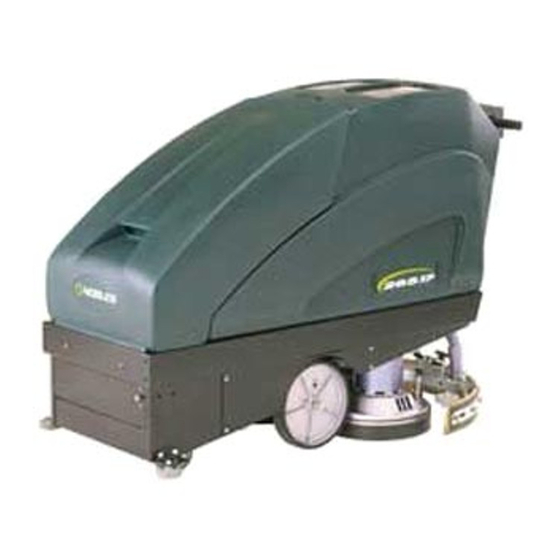
Nobles 265XP 608338 Operator And Parts Manual
Automatic floor scrubber
Hide thumbs
Also See for 265XP 608338
:
Brochure
(2 pages)
1
Table Of Contents
2
3
4
5
6
7
8
9
10
11
12
13
14
15
16
17
18
19
20
21
22
23
24
25
26
27
28
29
30
31
32
33
34
35
36
37
38
39
40
41
42
43
page
of
43
Go
/
43
Contents
Table of Contents
Troubleshooting
Bookmarks
Table of Contents
Table of Contents
Safety Precautions
Controls and Instruments
Operator Responsibility
Receipt of Machine
Battery Installation
Brush and Pad Driver Installation
Squeegee Tool Installation
Filling the Solution Tank
Machine Operation
Est Switch (Option)
Cleaning with the Machine
Operating Tips
Emptying the Tanks
Squeegee Adjustments
Squeegee Blade Replacement
Other Uses for the Machine
Routine Maintenance
Maintenance Chart
Daily Maintenance
Before each Use
After each Use
Battery Maintenance
Charging the Batteries
Weekly Maintenance
Monthly Maintenance
Quarterly Maintenance
Optional Kits and Attachments
Trouble Shooting
Specifications
Home Find
Drive Carriage Assembly
Machine Frame (Front)
Machine Frame (Rear)
Scrubber Head Assembly
Scrubber Head Mounting
Squeegee Assembly
Squeegee Arm Assembly
Control Console Assembly
Tank Assembly
Electrical Panel
Electrical Panel (Cont'D.)
Battery Group
Standard Parts
Breakdowns
Pad Motor & Drive Motor
Options
Wall Roller Kit
Est Option Components
Electrical Diagrams
Wiring Diagram
Ladder Diagram
265Xp
Advertisement
Quick Links
1
Standard Parts
Download this manual
Model No.:
608338
608339 – Pac
609246 – Can. Pac
NOBLES
12875 RANSOM STREET
HOLLAND MI 49424 U.S.A.
CUSTOMER SERVICE: 1-800-365-6625
FAX: 1–800–678–4240
Home
Find... Go To..
265XP
Automatic Floor Scrubber
Operator and Parts Manual
Rev. 00 (09-99)
608370
Table of
Contents
Previous
Page
Next
Page
1
2
3
4
5
Advertisement
Table of Contents
Need help?
Do you have a question about the 265XP 608338 and is the answer not in the manual?
Ask a question
Questions and answers
Related Manuals for Nobles 265XP 608338
Floor Machine Nobles 265 XP Brochure
Automatic walk-behind scrubbers (2 pages)
Floor Machine Nobles 27 Specifications
Sweepers (1 page)
Floor Machine Nobles 24 Specifications
Sweepers (1 page)
Floor Machine Nobles 24 Brochure
Cordless vacuum/sweeper (2 pages)
Floor Machine Nobles Speedshine 1700DS Specifications
Burnishers - single speed (2 pages)
Floor Machine Nobles Speedshine 1700LS Operator And Parts Manual
(30 pages)
Floor Machine Nobles Speedshine 608235 1700LS Operator And Parts Manual
(20 pages)
Floor Machine Nobles Concorde Brochure
Automatic & canister extractors (2 pages)
Floor Machine Nobles FALCON 2800 PLUS Operator And Parts Manual
Automatic carpet extractor (43 pages)
Floor Machine Nobles Speed Scrub 2001HD Operator And Parts Manual
Automatic scrubber (39 pages)
Floor Machine Nobles Speed Scrub 2001HD 612214 Operator And Parts Manual
(105 pages)
Floor Machine Nobles 265XP 608339 Operator And Parts Manual
Automatic floor scrubber (43 pages)
Floor Machine Nobles 265XP 609246 Operator And Parts Manual
Automatic floor scrubber (43 pages)
Floor Machine Nobles Speed Scrub 2001 612946 Operator And Parts Manual
Electric automatic scrubber (49 pages)
Floor Machine Nobles 28 Specifications
Sweepers (1 page)
Floor Machine Nobles Speedshine 1600 Specifications
Burnishers (1 page)
This manual is also suitable for:
265xp 608339
265xp 609246
265xp
608338
608339
609246
Table of Contents
Print
Rename the bookmark
Delete bookmark?
Delete from my manuals?
Login
Sign In
OR
Sign in with Facebook
Sign in with Google
Upload manual
Upload from disk
Upload from URL


Need help?
Do you have a question about the 265XP 608338 and is the answer not in the manual?
Questions and answers