
Related Manuals for LSI Symbios SYM22801


Summary of Contents for LSI Symbios SYM22801
-
Page 1: Scsi Host Adapter
Symbios ™ SYM22801 Dual Channel PCI to Ultra SCSI Host Adapter User’s Guide Version 2.0 ® S14017... - Page 2 Federal Communications Commission (FCC) Declaration of Conformity...
- Page 3 LSI Logic; nor does the purchase or use of a product from LSI Logic convey a license under any patent rights, copyrights, trademark rights, or any other of the intellectual property rights of LSI Logic or third parties.
-
Page 5: Table Of Contents
Contents Chapter 1 Using the SYM22801 Host Adapter General Description Features 1.2.1 1.2.2 1.2.3 Interface Descriptions 1.3.1 1.3.2 1.3.3 Chapter 2 Installing the SYM22801 Host Adapter Quick Installation Procedure Detailed Installation Procedure 2.2.1 2.2.2 2.2.3 2.2.4 2.2.5 SCSI Bus Termination 2.3.1... - Page 6 Chapter 3 Configuring the Host Adapter When to Configure the SYM22801 Host Adapter Starting the SCSI BIOS Configuration Utility 3.2.1 3.2.2 3.2.3 Exiting the SCSI BIOS Configuration Utility Appendix A Technical Specifications Physical Environment A.1.1 Electrical Characteristics A.2.1 A.2.2 A.2.3 Operational Environment A.3.1...
- Page 7 Internal SCSI Device Termination External SCSI Device Termination Internal and External SCSI Device Termination Internal and Internal SCSI Device Termination Termination Override Switch Settings for U1 and U2 SYM22801 Mechanical Drawing SCSI ID Record Setting Interrupts Global Default Settings Device Default Settings...
- Page 8 viii Contents...
- Page 9 Preface This book is the primary reference and User’s Guide for the LSI Logic Symbios ™ SYM22801 Dual Channel PCI to Ultra SCSI Host Adapter. It contains a complete functional description for the SYM22801 and includes complete physical and electrical specifications for the SYM22801.
- Page 10 Appendix B, Glossary of Terms and definitions of various terminology that is referenced throughout this user’s guide. Related Publications PCI SCSI Device Management System SDMS 4.0 User’s Guide, Document No. DB15-000099-01 Preface Abbreviations, provides...
-
Page 11: Chapter 1 Using The Sym22801 Host Adapter
This guide and the PCI SCSI Device Management System SDMS 4.0 User’s Guide contain product information and installation instructions to help you gain the full benefits of the SYM22801 Dual Channel PCI to Ultra SCSI host adapter for your computer system. -
Page 12: Features
1.2 Features This section provides a high level overview of the PCI Interface, the SCSI Interface, and Board Chacteristics for the SYM22801 Host Adapter board. 1.2.1 PCI Interface Full 32-bit DMA bus master Zero wait-state bus master data bursts Universal PCI bus voltage support 1.2.2 SCSI Interface... -
Page 13: Interface Descriptions
PCI is a high-speed standard local bus for interfacing a number of I/O components to the processor and memory subsystems in a high end PC. The PCI functionality for the SYM22801 is contained within the Symbios SYM53C876 PCI to Ultra SCSI I/O Processor chip. The SYM53C876 connects directly to the PCI bus and generates timing protocol in compliance with the PCI specification. -
Page 14: Installing The Sym22801 Host Adapter
LED lights when TERMPWR is shorted. Separate switches for each channel allow user override of termination. A 40 MHz oscillator is installed on the SYM22801 to provide the clock frequency to the SYM53C876 that is necessary to support Wide Ultra SCSI transfers of up to 40 Mbytes/s. -
Page 15: Quick Installation Procedure
Chapter 2 Installing the SYM22801 Host Adapter This chapter provides instructions on how to install the SYM22801 Host Adapter and includes these topics: Section 2.1, “Quick Installation Procedure,” page 2-1 Section 2.2, “Detailed Installation Procedure,” page 2-3 Section 2.3, “SCSI Bus Termination,” page 2-18 Section 2.4, “Setting Interrupts,”... - Page 16 The use of a static ground strap is recommended. Refer to the user’s manual for your computer to confirm the location of the PCI slots. The SYM22801 requires a PCI slot that allows bus master operation. with the PCI slot you intend to use. Save the bracket screw.
-
Page 17: Detailed Installation Procedure
2.2 Detailed Installation Procedure This section provides step-by-step instructions for installing the SYM22801 host adapter and connecting it to your SCSI peripherals. If you are experienced in these tasks, you may prefer to use the preceding Section 2.1, “Quick Installation Procedure.” If you are not confident that you can perform the tasks as described here, LSI Logic suggests getting assistance. -
Page 18: Inserting The Host Adapter
SCSI peripherals. Each chain of SCSI peripheral devices and their host adapter work together, and are referred to as a SCSI bus. Each SYM22801 host adapter that you install can access up to 15 peripheral devices per channel. -
Page 19: Hardware Connections For The Sym22801 Host Adapter
Figure 2.1 Hardware Connections for the SYM22801 Host Adapter C hannel A LED C onnector C hannel A 68-pin Internal H igh D ensity S C S I Interface C hannel A C hannel A 68-pin External 50-pin Internal V HD C I... -
Page 20: Connecting The Scsi Peripherals
Step 8. The bracket around the connectors J3 and J7 (see Figure 2.1) 2.2.3 Connecting the SCSI Peripherals SCSI bus connections to the SYM22801 host adapter inside the computer are made with an unshielded, 68 or 50-conductor ribbon cable (see Figure 2.3). One side of this cable is marked with a color to indicate the pin-1 side. -
Page 21: Scsi Cables
All external SCSI bus connections to the SYM22801 host adapter are made with shielded, 68-conductor cables (see Figure 2.3). The connectors on this cable are always keyed to ensure proper pin-1 connection. Figure 2.3 SCSI Cables S C S I C a b le s fo r In te rn a l C o n n e c tio n s... -
Page 22: Making Internal Scsi Bus Connections
SCSI cables into the SYM22801 SCSI connectors. If you connect the SYM22801 in the middle of the bus, you will incur improper termination since the switches are not assigned on that bus correctly. Refer to the Channel Switches section for more information. -
Page 23: Internal Wide Scsi Ribbon Cable To Host Adapter Connection
Figure 2.4 Internal Wide SCSI Ribbon Cable to Host Adapter Connection Step 2. To connect an 8-bit internal SCSI device, plug the 50-pin connector on one end of an 8-conductor internal SCSI ribbon cable into the connector J4 or J8 (see Figure 2.5). Make certain to match pin-1 on both connectors. -
Page 24: Internal Scsi Ribbon Cable To Host Adapter Connection
Figure 2.5 Step 3. Plug the 68 or 50-pin connector on the other end of the internal 2-10 Installing the SYM22801 Host Adapter Internal SCSI Ribbon Cable to Host Adapter Connection C hannel B C hannel A SCSI ribbon cable into the SCSI connector on the internal SCSI device. -
Page 25: Internal Scsi Ribbon Cable To Internal Scsi Device Connection
Figure 2.6 Internal SCSI Ribbon Cable to Internal SCSI Device Connection Step 4. Additional internal SCSI devices are plugged in by using an internal SCSI ribbon cable with the required number of connectors attached along its length as shown in Figure 2.7. An example of this type of chained connection is shown in Figure 2.8. -
Page 26: Connecting Additional Internal Scsi Devices
Figure 2.7 Connecting Additional Internal SCSI Devices 2-12 Installing the SYM22801 Host Adapter... -
Page 27: Multiple Internal Scsi Devices Chained Together
Figure 2.8 Multiple Internal SCSI Devices Chained Together Step 5. It is also possible to use both internal connectors on a channel if you do not attach any external devices to that channel. An example of this configuration is shown in Figure 2.9. Detailed Installation Procedure 2-13... -
Page 28: Using Both Internal Connectors On A Channel
Note: Step 6. Most PC cabinets are designed with a front panel LED 2-14 Installing the SYM22801 Host Adapter Using Both Internal Connectors on a Channel When two connectors are already used on a channel, the third connector cannot be used. -
Page 29: Making External Scsi Bus Connections
2.2.5 Making External SCSI Bus Connections This section provides step-by-step instructions about making internal SCSI bus connections: Step 1. To connect external SCSI devices to the SYM22801 host Detailed Installation Procedure adapter, plug the 68-pin connector on one end of a shielded external SCSI VHDCI cable (see Figure 2.3) into the host... -
Page 30: External Cable To Host Adapter
Figure 2.11 External Cable to Host Adapter Step 2. Plug the 68-pin connector on the other end of the shielded 2-16 Installing the SYM22801 Host Adapter external SCSI cable into the SCSI connector on your external SCSI device. An example of this connection is shown in... -
Page 31: External Cable To External Scsi Device
Figure 2.12 External Cable to External SCSI Device Step 3. To connect more than one external SCSI device to the host adapter, you must chain them together with shielded external SCSI cables. An example of these chained connections is shown in Figure 2.13. Detailed Installation Procedure 2-17... -
Page 32: Scsi Bus Termination
SCSI bus must have a set of resistors called terminators. All other SCSI devices on the bus must have their terminators removed or disabled. Remember: The SYM22801 host adapter is also on the SCSI bus; its 2-18 Installing the SYM22801 Host Adapter termination is automatically enabled when it is connected to the end of the bus. -
Page 33: Internal Scsi Connections
Caution: The SYM22801 senses SCSI devices by detecting the ground signal on pin-22 of a 50-conductor internal SCSI ribbon cable, or pin-50 of an internal or external 68-conductor SCSI cable. If you use an adapter to connect 8-bit devices externally with a 50-conductor SCSI cable, the ground signal is detected on pin-34. -
Page 34: External Scsi Connections
Termination on the host adapter is automatically enabled in this case. Figure 2.15 shows an example of how termination is determined for this SCSI bus configuration. 2-20 Installing the SYM22801 Host Adapter... -
Page 35: Internal And External Scsi Connections
Figure 2.15 External SCSI Device Termination L a st D e v ic e o n C h a in - Te rm in a tio n E n a b le d 2.3.3 Internal and External SCSI Connections If you have internal and external SCSI device connections to the host adapter, you must terminate the last internal and external devices on the SCSI bus. -
Page 36: Internal Scsi Connections For Both Internal Connectors
SCSI bus. You must disable the termination on all other devices. Termination on the host adapter is automatically disabled in this case. Caution: 2-22 Installing the SYM22801 Host Adapter Te rm in a tio n D is a b le d L a st D e vice... -
Page 37: Internal And Internal Scsi Device Termination
Figure 2.17 shows an example of how termination is determined for this SCSI bus configuration. If you connect the SYM22801 in the middle of the bus, you will incur improper termination since the switches are not assigned on that bus correctly. - Page 38 68-pin connector. When SYM22801 is in the middle of a bus using only one connector, then switch Int68 and Ext68 (switches 2 and 4) for that bus are on. This forces the terminators for that bus to be disabled.
-
Page 39: Setting Scsi Ids
Use this switch only w hen a device is connected to the internal 50 pin connector that does not ground pin 22, like another LSI Logic host adapter. 2-INT68 Sim ulates a device on the Internal 68 pin connector. Use this switch only w hen a... -
Page 40: Scsi Id Record
Table 2.1 SCSI ID 2-26 Installing the SYM22801 Host Adapter any duplications and if 8-bit SCSI devices are to be used, the host adapter ID must not be set above 7. IDs for future reference. The following table is provided as a place to keep this record. -
Page 41: Setting Interrupts
2.4 Setting Interrupts You should not normally have to change the default interrupt routing for the SYM22801, since performance is usually increased by having two separate interrupts. However, if your system does not support two separate interrupts, jumper TP9 (see Figure A.1) is provided to change the interrupt routing. -
Page 42: Completing Your Installation
Step 4. To change the configuration of your host adapter, see Step 5. Finally, refer to the PCI SCSI Device Management System 2-28 Installing the SYM22801 Host Adapter your computer. Chapter 3, Configuring the Host Adapter. SDMS 4.0 User’s Guide (or the guide for the software you plan to use) to load the driver software for your particular operating system. -
Page 43: Chapter 3 Configuring The Host Adapter
Settings for the Host Adapter and All Devices SCAM Support Parity Checking Host Adapter SCSI ID Scan Order 1. Applies to BIOS version 4.09 and later. Symbios SYM22801 Dual Channel PCI to Ultra SCSI Host Adapter Global Default Settings Default Settings Enabled Low to High (0-Max) -
Page 44: Starting The Scsi Bios Configuration Utility
After a brief pause, your computer monitor displays the Main Menu of the Symbios SCSI BIOS Configuration Utility. NVRAM (Non Volatile Random Access Memory) is available on the SYM22801 host adapter. Changes can be made and stored to NVRAM using this menu driven utility. Configuring the Host Adapter... -
Page 45: Configuration Utility Main Menu
Menu appears. This menu displays a list of up to four Symbios PCI to SCSI host adapters in your system and information about each of them. The SYM22801 host adapter appears on the menu as two SYM53C875 entries; one for each channel. To select an adapter, use only the arrow keys and enter key. - Page 46 3.2.1.2 Adapter Boot Order The adapter boot order allows the user to set the order in which host adapters will boot when you have more than one LSI Logic host adapter in your system. When this option is selected, the Boot Order menu appears.
- Page 47 To change an adapter's boot order, select it and press Enter. You are then prompted to enter the new boot sequence number. To remove an adapter's boot order, press Enter again rather than entering a new sequence number. While the maximum capacity is 32 adapters, only four adapters can be assigned a boot order starting with boot sequence number zero (0).
-
Page 48: Utilities Menu
3.2.1.6 Language If enabled, the Language option allows you to select from five languages for the configuration utility: English, German, French, Italian, and Spanish. 3.2.1.7 Help The Help option allows the user to bring up a help screen with information about the Main Menu. 3.2.1.8 Quit The Quit option allows exiting from the SCSI BIOS Configuration Utility when the Main Menu is displayed. - Page 49 3.2.2.1 Adapter Setup Menu When you select Adapter Setup, the corresponding menu appears. Here is an example of the Adapter Setup Menu: Adapter Setup SCAM Support Parity Host SCSI ID Scan Order Removable Media Support None CHS Mapping Spinup Delay (sec) Help Restore Default Setup Exit this menu...
- Page 50 Note: Host SCSI ID – This option refers to the host adapter’s SCSI ID, which is a unique number used to identify the device on the SCSI bus. Note: Scan Order – This option allows the user to tell the SCSI BIOS and device drivers to scan the SCSI bus from low to high (0 to max) SCSI ID, or from high to low (max to 0) SCSI ID.
- Page 51 With Media Installed provides removable media support wherever the drive(s) actually resides. One of these choices can be selected by highlighting it and pressing Enter. CHS Mapping – This option defines the cylinder head sector (CHS) values that will be mapped onto a disk without pre-existing partition information.
-
Page 52: Device Selections Menu
3.2.3 Device Selections Menu When you select the Device Selections option, the corresponding menu appears: Device Selections 0-7 0-Dev0 N/A 1-Dev1 N/A 2-Dev2 N/A 3-Dev3 N/A 4-Dev4 N/A 5-Dev5 N/A 6-Dev6 N/A SYM53C875 Device Selections 8-15 Help Exit this menu The settings in this menu affect individual SCSI devices attached to the selected host adapter. - Page 53 SYM53C875 Inside device Sync Rate Width Disconnect Read/Write I/O Timeout Scan for Device at Boot Time Scan for SCSI LUNs Queue Tags Initial Boot Format Verify Help Restore Default Setup Exit this menu Please review the descriptions of each option below before changing any values.
- Page 54 Disconnect – SCSI devices have the ability to disconnect from the initiator during an I/O transfer. This disconnect option frees the SCSI Bus to allow other I/O processes. This option tells the host adapter whether or not to allow a device to disconnect. Some devices run faster with disconnects enabled (mostly newer devices), while some run faster with disconnects disabled (mostly older devices).
-
Page 55: Exiting The Scsi Bios Configuration Utility
Verify – This option allows the user to read all the sectors on a disk looking for errors. When selected, this option displays the following message: Help – This option brings up a help screen with information about the Device Selections Menu. Restore Default Setup –... - Page 56 3-14 Configuring the Host Adapter...
-
Page 57: A.1.1 Physical Characteristics
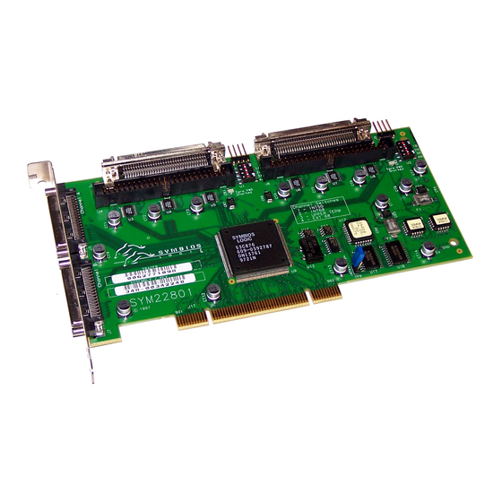
FCC. A.1.1 Physical Characteristics The dimensions of the SYM22801 host adapter board are 7.50” x 3.80”. PCI connection is made through the edge connector J1. Internal 16-bit SCSI connection is made through the 68-pin high density connectors J2 or J6. -
Page 58: A.2 Electrical Characteristics
Figure A.1 A.2 Electrical Characteristics The SYM22801 maximum power requirements, including SCSI TERMPWR, under normal operation are as follows: + 5 V DC + 12 V + 3.3 V Under abnormal conditions such as a short on SCSI TERMPWR, + 5 V current may be higher. -
Page 59: A.2.2 Electromagnetic Compliance
PCI bus slot, all voltages are below the SELV 42.4 V limit. A.3 Operational Environment The SYM22801 is designed for use in PCI computer systems with an ISA/EISA bracket type. The Symbios SDMS™ (SCSI Device Management System) software operates the board, but the design of the board does not prevent the use of other software. -
Page 60: Pci Connector J1 (Front
Note: Table A.1 Signal Name 12 V +5 V +5 V INTB/ INTD/ GND (PRSNT1/) RESERVED GND (PRSNT2/) KEYWAY KEYWAY RESERVED REQ/ 3 V/5 V AD31 AD29 Shaded signals are not connected. Technical Specifications The + 3.3 V pins are tied together and decoupled with high frequency bypass capacitors to ground. -
Page 61: Pci Connector J1 (Back
Table A.2 PCI Connector J1 (Back) Signal Name Signal Name TRST/ AD28 +12 V AD26 AD24 +5 V IDSEL INTA/ +3.3 V INTC/ AD22 +5 V AD20 RESERVED 3 V/5 V AD18 RESERVED AD16 KEYWAY +3.3 V KEYWAY FRAME/ RESERVED RST/ TRDY/ 3 V/5 V... -
Page 62: The Scsi Interface
A.3.2 The SCSI Interface The SCSI interface operates as 8-bit or 16-bit, synchronous or asynchronous, single-ended bus, and supports SCSI-2 protocols and 16-bit arbitration. The interface is made through connectors J2, J3 and J4 for channel A. Channel B connectors are J6, J7, and J8. Connectors J2 and J6 are 68-pin high density right angle receptacles for internal connections. -
Page 63: Scsi Connectors J2/J6 And J3/J7
Table A.3 SCSI Connectors J2/J6 and J3/J7 Signal Name Signal Name GND (J2/J6) GND/16CBLSNS (J3/J7) SD12/ SD13/ SD14/ SD15/ SDP1/ TERMPWR SD0/ TERMPWR SD1/ SD2/ SD3/ SD4/ SD5/ SD6/ CPRSNT_A/ (J2/J6) and CPRSNT_B/ (J3/J7) are used to sense the connection of a standard SCSI device by sensing SCSI standard GND on this pin. -
Page 64: Scsi Connectors
Table A.4 Signal Name CPRSNT_C/ is used to sense the connection of a standard SCSI device by sensing SCSI standard GND on this pin. Technical Specifications SCSI Connectors J4/J8 Signal Name SD0/ SD1/ SD2/ SD3/ SD4/ SD5/ SD6/ SD7/ SDP/ CPRSNT_C/ TERMPWR SATN/... -
Page 65: The Led Interface
GPIO0_FETCH line (maximum output low voltage 0.4 V and minimum output low current 16 mA) is pulled low to complete the circuit when a harness with an LED is attached. The connectors on the SYM22801 are J5 and J9. Table A.5... - Page 66 A-10 Technical Specifications...
-
Page 67: Appendix B Glossary Of Terms And Abbreviations
Appendix B Glossary of Terms and Abbreviations Address A specific location in memory, designated either numerically or by a symbolic name. Asynchronous A method of transmission which does not require a common clock, but Data Transfer separates fields of data by stop and start bits. It is slower than synchronous data transfer. - Page 68 Configuration Refers to the way a computer is set up; the combined hardware components (computer, monitor, keyboard, and peripheral devices) that make up a computer system; or the software settings that allow the hardware components to communicate with each other. Central Processing Unit.
- Page 69 Firmware Software that is permanently stored in ROM. Therefore, it can be accessed during boot time. Hard Disk A disk made of metal and permanently sealed into a drive cartridge. A hard disk can store very large amounts of information. Host The computer system in which a SCSI host adapter is installed.
- Page 70 Motherboard See Mainboard. In some countries, the term Motherboard is not appropriate. Multi-tasking The executing of more than one command at the same time. This allows programs to operate in parallel. Multi-threading The simultaneous accessing of data by more than one SCSI device. This increases the data throughput.
- Page 71 CPU. Information can be written to and read from RAM. The contents of RAM are lost when the computer is turned off. RISC Core LSI Logic SCSI chips contain a RISC (Reduced Instruction Set Computer) processor, programmed through microcode scripts. Read Only Memory. Memory from which information can be read but not changed.The contents of ROM are not erased when the computer is...
- Page 72 15 for Wide SCSI). The host adapter usually gets ID 7 giving it priority to control the bus. SDMS SCSI Device Management System. A LSI Logic software product that manages SCSI system I/O. SCSI Trade Association. A group of companies that cooperate to promote SCSI parallel interface technology as a viable mainstream I/O interconnect for commercial computing.
- Page 73 CHS mapping auto-termination enabled/disabled 2-19–2-22 scheme BIOS support for the SYM22801 board board characteristics SYM22801 dimensions SYM22801 host adapter boot order menu changing an adapter’s boot order example removing an adapter’s boot order setting the boot order...
- Page 74 Ext68 channel switch (switch 4) 2-24 external SCSI bus connections making 2-15–2-17 FDISK /MBR command removing partition features SYM22801 board Flash BIOS format device option low-level formatting 3-12 removing partitions/data front panel LED 2-14 global default settings table...
- Page 75 PCI interface SCSI interface A-6, software SCSI Device Management System (SDMS) 1-1, spinup delay switches providing cable detection simulation SYM22801 host adapter 40 MHz oscillator accessing peripheral devices active termination 1-3, BIOS support board characteristics Index channel switches 1-4,...
- Page 76 utilities menu adapter setup option 3-7–3-9 device selections option 3-10–3-13 example exiting verbose setting verify option 3-13 VHDCI connectors 68 pin 1-3, 2-15, IX-4 Index...
-
Page 77: Customer Feedback
Customer Feedback We would appreciate your feedback on this document. Please copy the following page, add your comments, and fax it to us at the number shown. If appropriate, please also fax copies of any marked-up pages from this document. Important: Please include your name, phone number, fax number, and company address so that we may contact you directly for... - Page 78 Reader’s Comments Fax your comments to: Please tell us how you rate this document: Symbios™ SYM22801 Dual Channel PCI to Ultra SCSI Host Adapter User’s Guide. Place a check mark in the appropriate blank for each category. Completeness of information...
- Page 79 U.S. Distributors by State H. H. Hamilton Hallmark Georgia W. E. Wyle Electronics Atlanta H. H. Alabama W. E. Huntsville Hawaii H. H. Tel: 205.837.8700 H. H. W. E. Tel: 800.964.9953 Idaho Alaska H. H. H. H. Tel: 800.332.8638 Illinois Arizona North/South Phoenix...
- Page 80 LSI Logic International Edison Services Inc Tel: 732.549.4500 Tel: 86.10.6804.2534.40 Fax: 732.549.4802 Fax: 86.10.6804.2521 Korea Denmark Seoul Ballerup LSI Logic Corporation of LSI Logic Development Korea Ltd Centre Tel: 82.2.528.3400 Tel: 45.44.86.55.55 Fax: 82.2.528.2250 Fax: 45.44.86.55.56 The Netherlands France Eindhoven...
Need help?
Do you have a question about the Symbios SYM22801 and is the answer not in the manual?
Questions and answers