
Related Manuals for Lowrance LVR-850


Summary of Contents for Lowrance LVR-850
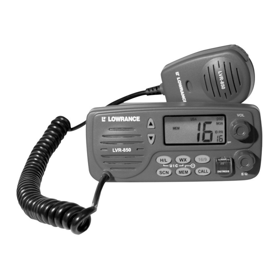
- Page 1 Pub. 988-0158-001 www.lowrance.com LVR-850 LVR-850 DSC VHF Marine Radio Installation and Operation Instructions...
- Page 2 Copyright © 2005 Lowrance Electronics, Inc. All rights reserved. ® Lowrance is a registered trademark of Lowrance Electronics, Inc. No part of this manual may be copied, reproduced, republished, transmitted or distributed for any purpose, without prior written consent of Lowrance. Any unauthorized commercial distribution of this manual is strictly prohibited.
-
Page 3: Table Of Contents
Section 1: Installation ... 1 Introduction ... 1 Powering Your Radio ... 1 Auxiliary Wires ... 1 Bracket Installation ... 2 Antenna ... 3 How to Make a Distress Call... 4 Section 2: Basic Radio Operation ... 5 Using the Keypad ... 5 Power/Volume ... - Page 4 Channels... 19 Channel Bank ... 19 Directory... 20 Storing/Editing MMSI Data ... 20 DSC Monitor ... 21 GPS Operation ... 22 H/L ... 22 Memory Operation ... 22 Position Send/Request ... 23 Transmission ... 23 Reception ... 24 Priority Channel (16/9) ... 25 PTT (Push To Talk)...
- Page 5 FCC Digital Device Compliance This device complies with Part 15 of the U.S. Federal Communi- cations Commission (FCC) Rules. Operation is subject to the fol- lowing two conditions: (1) this device may not cause harmful in- terference, and (2) this device must accept any interference re- ceived, including interference that may cause undesired opera- tion.
- Page 6 FCC Radio Frequency Compliance Requirements and Warnings When operating your marine radio transceiver, you should know that the antenna radiates radio frequency (RF) energy. This radio was de- signed to meet the FCC’s rules and regulations for the maximum per- missible exposure to radio frequency energy.
-
Page 7: Section 1: Installation
We put it at the front of the book to make it easy to find in case of an emergency. The first section covers LVR-850 installation and specifications. The second section, Basic Radio Operation, goes over some basic func- tions of the radio and includes instructions on how to set up your MMSI (Maritime Mobile Service Identity) number. -
Page 8: Bracket Installation
The remaining auxiliary wires are used for DSC (Digital Selective Calling) service, where the radio can exchange latitude and longitude position information with a GPS (Global Positioning System) receiver in NMEA 0183 format. To GPS unit Shield – (Ground) Wiring to transmit NMEA information To GPS unit Shield (Ground) Wiring to receive NMEA position information... -
Page 9: Antenna
Screw mounting hole Front Install the gimbal bracket, which looks similar to the one pictured here. Place the bracket so the arms slope toward the radio's front. Once a location is determined, use the bracket as a template and mark the mounting holes. -
Page 10: How To Make A Distress Call
sure your antenna and its installation complies with all local and fed- eral regulations. Never operate your radio unless it is connected to the antenna. The antenna must not exceed an antenna gain of 3 decibels (dB). The antenna cable requires a PL259 connector, and the cable connects at the back of the radio. -
Page 11: Section 2: Basic Radio Operation
In those cases, a single beep sounds, then, after a few moments, a second beep will be heard to let you know you have successfully changed the mode. The Lowrance LVR-850 VHF Marine Radio. (Hi/Lo),... -
Page 12: Power/Volume
Power/Volume The volume knob at the top right of the radio’s face is used to power up the LVR 850. Turn the knob clockwise to turn on the radio. The unit will start on Ch. 2, then switch to Ch. 16, its default priority channel. Squelch Squelch, the bottom knob on the radio’s face, helps the unit screen out radio traffic resulting from signals that are too weak to transmit any-... -
Page 13: Mem (Memory)
DSC Calling vs. non-DSC Calling The LVR-850 supports two types of calls, Digital Selective Calls (DSC) and non-Digital Selective Calls. A non-DSC call is the traditional method where an individual hails another vessel on Ch. 16, then asks the other party to switch to a working channel set aside for the desired communication type. -
Page 14: How Dsc Works
fire, you could not man the radio and fight the fire at the same time. DSC calling also helps cut back the transmission traffic on Ch. 16, the emergency priority channel. How DSC works A digital selective call uses a digital signal to transmit a pack of infor- mation that can include, the caller’s MMSI number, the MMSI of the ship or ships being called, call priority and a frequency or mode re- quest. -
Page 15: Mmsi Setup
The figure above illustrates the MMSI number entry of 992344513. If a valid MMSI is already stored in the radio's memory, you will not be able to enter a MMSI number. If a 9-digit MMSI number has not been programmed into the radio, you will not be able to make or receive DSC calls. -
Page 16: Choosing A Channel
You'll have to choose a simplex communication channel authorized for the type of communication you desire. Making a Call The LVR-850 supports five DSC call types: . For information on the other call types, see page 13. To place a DSC call New Call 1. -
Page 17: Receiving A Call
call key again and the call is placed again. You can exit the call func- tion at any time by pressing the CAUTION Before transmitting, monitor the selected simplex channel to make sure it is clear. This is a FCC requirement. MMSI Digit For more in depth information on placing calls see page 13. - Page 18 the calling vessel’s MMSI matches a number stored in your directory, the number's directory location is shown. If no match is made, the blinks. If you want to respond to the calling vessel, just ANNUNCIATOR press the button on the microphone. Press the 16/9 key to ignore the call.
-
Page 19: Section 3: Advanced Operation
We'll start off with a breakdown of the types of DSC calls the LVR-850 can transmit and receive. That will be followed by a brief de- scription of how to place a non-DSC call. If you are comfortable with your knowledge regarding transmission and reception of calls, skip ahead to page 20 to see how to set up a MMSI Directory. -
Page 20: Directory Call
Directory Call See page 20 to learn how to setup a MMSI directory. To call a number from your directory: 1. Use the ↑ ↓ keys to select a simplex-working channel. 2. Press the key. CALL 3.Use the ↑ ↓ keys to select the call type — . - Page 21 three seconds. The radio switches to Ch. 16 and a three-second on screen timer begins to count down in the bottom right corner of the screen. When it reaches zero, the call is sent out. To stop the call, let go of the key.
-
Page 22: Last Call
When an is received, the distress mode is automatically can- celed and communication will be on Ch. 16. Last Call You can send a last call by following this sequence: 1. Use the ↑ ↓ keys to select a simplex-working channel. The radio will default to Ch. - Page 23 NEW and ID Annunciators will blink Channel ↑ ↓ 4. Use the keys to set proper MMSI data for the digit shown. After correct verification of the first digit of the MMSI number, touch the key to advance. The small digit now displays the 2nd character position with a "0"...
-
Page 24: Reception
1. Distress relay from an intermediary vessel. 2. Distress relay acknowledgment Geographic Call The LVR-850 is able to receive geographic calls. When it does, a ring tone sounds and the calling radio's requested working channel is chosen for communication. There is no... -
Page 25: Individual Call
Channels To tune into one of the 84 channels on the LVR-850 radio, use the ↑ ↓ keys to scroll through the channels. Refer to the enclosed channel chart in the back of this book for proper usage and understanding. In the US and Canada, (Weather) channels are available. -
Page 26: Directory
Directory The Directory is an organized list of (up to 10) MMSI numbers stored on the DSC calling directory. Storing/Editing MMSI Data To store a new MMSI in an unused location, follow these steps: 1. Press the key to display CALL ANNUNCIATOR 2. -
Page 27: Dsc Monitor
The example shows the MMSI Data 987776510 being entered. To change or edit MMSI data, select a location and press the key to change the data. After inputting the 9-digit MMSI, hold down key for 5 seconds to store the new MMSI. CALL DSC Monitor To be sure the DSC Monitor mode is on, hold down the... -
Page 28: Gps Operation
NOTE DSC calls will NOT be received when the radio is receiving or sending out a transmission. During scanning, Ch. 70 is monitored on an allocated time-slot basis and DSC calls will be received. GPS Operation Your radio is NMEA 0183 compatible, which means it can work with a GPS unit. -
Page 29: Position Send/Request
You can easily add or delete channels from the memory channel list. For your safety, DO NOT delete priority Ch. 16. To add a new channel, use the ↑ ↓ keys to select the desired channel (shown above in big digits). If the channel is currently stored as a memory channel, the To add a new channel to the list, hold down the appears. -
Page 30: Reception
3. Press the Call key and the big digit will blink and the channel will switch to Ch. 16. Press the sent through Ch. 70. After the transmission on Ch. 70, the ID Annun- ciator will flash, indicating it is waiting for an received, another call can be made to send your position to the same MMSI by pressing the edged, an alarm will be heard. -
Page 31: Priority Channel (16/9)
To receive a position request: 1. The alarm will sound and P1 will be displayed on the screen in big digits. The MMSI directory location will be shown next to it, in small digits. 2. To send your position, press the 3. - Page 32 NOTE Remember, you cancel any scan mode at anytime by pressing the key. 16/9 To start an All Scan To scan through all available channels, press and hold the three seconds. ALL SCN scroll through every available channel as it scans. A noisy channel that interrupts the scanning can be temporarily elimi- nated from the scan list by holding down the ceiving the signal will be skipped, allowing the scanning to continue...
-
Page 33: Weather (Wx)
pear on the display. The priority channel is scanned every 2 seconds, even if another channel has a squelch break. When a signal is received on the priority channel, the scan stops and the radio receives the priority transmission. and on by pressing the Screen When the unit is turned on the LCD light display is on and stays on. -
Page 34: Frequency Charts & Usage
Frequency Charts & Usage Chan U I C S/D 01A X 156.050 X X D 156.050 160.650 Public Correspondence (Marine Operator). X X D 156.100 160.700 Public Correspondence (Marine Operator). 03A X 156.150 X X D 156.150 160.750 156.200 D 156.200 160.800 156.250 05A X D 156.250 160.850... - Page 35 Chan U I C S/D 20A X 157.000 X X D 157.000 161.600 21A X 157.050 157.050 161.650 Port operation, Ship movement. 22A X 157.100 157.100 161.700 Port operation, Ship movement. 23A X 157.150 157.150 161.750 Public Correspondence (Marine Operator). X X D 157.200 161.800 Public Correspondence (Marine Operator).
- Page 36 Chan U I C S/D 156.925 161.525 79A X 156.975 156.975 161.575 Port operations and ship movement. 80A X 157.025 157.025 161.625 Port operations and ship movement. 81A X 157.075 157.075 161.675 Port operations and ship movement. 82A X 157.125 157.125 161.725 157.175 157.175 161.775 Public Correspondence (Marine Operator).
- Page 37 LOWRANCE ELECTRONICS FULL ONE-YEAR WARRANTY "We," "our," or "us" refers to LOWRANCE ELECTRONICS, INC., the manufacturer of this product. "You" or "your" refers to the first person who purchases this product as a consumer item for personal, family or household use. We warrant this product against defects or malfunctions in materials and workmanship, and against failure to conform to this product's written specifications, all for one (1) year from the date of original purchase by you.
-
Page 38: Outside Canada And The Usa
How to Obtain Service… …in the USA: We back your investment in quality products with quick, expert service and genuine Lowrance parts. If you're in the United States and you have technical, return or repair questions, please contact the Factory Customer Service Depart- ment. -
Page 39: Accessory Ordering Information For All Countries
Accessory Ordering Information for all countries To order Lowrance accessories, please contact: 1) Your local marine dealer. Most quality dealers that handle marine electronic equipment should be able to assist you with these items. To locate a Lowrance dealer near you, visit our web site and look for the Dealer Locator (www.lowrance.com/support/dealerlocator). -
Page 40: Visit Our Website
Visit our web site: Lowrance Pub. 988-0158-001 Copyright © 2005 All Rights Reserved Printed in USA 030305 Lowrance Electronics, Inc.
Need help?
Do you have a question about the LVR-850 and is the answer not in the manual?
Questions and answers