Table of Contents
Advertisement
Advertisement
Table of Contents

Related Manuals for Lowrance LINK-8 VHF


Summary of Contents for Lowrance LINK-8 VHF
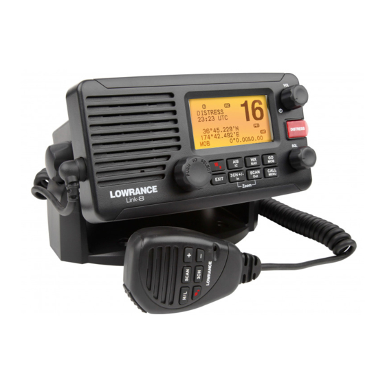
- Page 1 Link-8 VHF Installation Instructions ENGLISH lowrance.com...
- Page 2 Any unauthorized commercial distribution of this manual is strictly prohibited. Lowrance Electronics may find it necessary to change or end our policies, regulations, and special offers at any time. We reserve the right to do so without notice. All features and specifications subject to change without notice.
-
Page 3: Table Of Contents
3.2 Wiring diagram - NMEA 2000 ...................... 15 3.3 Wiring diagram - External speaker and hailer ............... 16 3.4 Wiring diagram - NMEA 0183 connections ................17 4 Setup your radio - Your user MMSI...............18 Lowrance - Link-8 Installation Instructions... -
Page 4: Important Safety Information
Lowrance VHF radio. The operator is solely responsible for observing proper radio installation and usage practices. A DSC warning label is supplied with this Lowrance VHF radio. To comply with FCC regulations, this label must be affixed in a location that is clearly visible from the operating controls of this radio. - Page 5 CE Compliance Statement This product complies with CE under R&TTE directive 1999/5/EC. The relevant Declaration of Con- formity is available in the following website under model documentation section: http://www.lowrance.com. Lowrance - Link-8 Installation Instructions...
-
Page 6: Installation Preparation
• Declaration of Conformity document 2 mounting knobs (where applicable) Note: A VHF antenna is not provided by Lowrance. Consult your Lowrance dealer for advice if necessary. 1.2 Tools needed for installation You will need the following tools: • Power drill (or hand drill) and drill bits • Philips screwdriver... -
Page 7: Vhf Installation
The radio can be removed for storage and the viewing angle can be adjusted. • In dash or recessed installation. The radio is recessed into a cavity cut into a bulkhead. The radio fixture is permanent and the viewing angle cannot be adjusted. Lowrance - Link-8 Installation Instructions... -
Page 8: Mounting Bracket Installation
Insert the 2 mounting knobs through the holes and tighten them sufficiently to hold the radio at your preferred viewing angle. You can adjust the viewing angle at any time. The viewing angle has a 20º tilt range. Now install the microphone wall hanger. Lowrance - Link-8 Installation Instructions... -
Page 9: Recessed Installation
Working from the rear of the bulkhead, screw the radio firmly to the mounting surface using the 2 M5 x 32 screws with the plain washers and nuts. (The screws should not be visible from the front of the radio). Now install the microphone wall hanger. Lowrance - Link-8 Installation Instructions... -
Page 10: Link-8 Dimensions
2.4 Link-8 dimensions Lowrance - Link-8 Installation Instructions... -
Page 11: Handset Mic Wall Hanger
• metallic, use the 2 flat screws, 2 spring washers and 2 nuts to attach the handset mic wall hanger to the mounting surface. Hang the handset mic on the handset mic wall hanger. Now connect the radio. 0.96" (24.5 mm) Lowrance - Link-8 Installation Instructions... -
Page 12: Vhf Electrical Installation
A suitable radio antenna (not supplied) must be mounted and connected before you can operate the radio. Consult your Lowrance dealer for advice, if necessary. Always mount the VHF antenna as high as possible and at least 37” (96 cm) from the base station. - Page 13 RS232 OUT (+) 38.4 kbps Grey RS232 IN Not used Note: The GPS connector on the radio is provided with a protective cover. If this connec- tor will not be used, please ensure the protective cover is fitted. Lowrance - Link-8 Installation Instructions...
- Page 14 The vessels battery negative must be common to the boat’s seawater Ground. (Optional) You can connect the base station to the boat’s seawater Ground. Use the Ground screw and Ground plain washer supplied to make this connection. Lowrance - Link-8 Installation Instructions...
-
Page 15: Wiring Diagram - Nmea 2000
3.2 Wiring diagram - NMEA 2000 Lowrance - Link-8 Installation Instructions... -
Page 16: Wiring Diagram - External Speaker And Hailer
3.3 Wiring diagram - External speaker and hailer VHF Antenna External Speaker Hailer Speaker Lowrance - Link-8 Installation Instructions... -
Page 17: Wiring Diagram - Nmea 0183 Connections
3.4 Wiring diagram - NMEA 0183 connections GPS Plotter Link-8 VHF Fuse Switch Black 12 VDC Power 12 VDC only Lowrance - Link-8 Installation Instructions... -
Page 18: Setup Your Radio - Your User Mmsi
See the Setup section in the Link-8 User Guide for full setup details. CAUTION Under extreme operating conditions, the temperature of the rear heat-sink on this radio may exceed normal surface temperatures. Caution is advised to prevent possible skin burns. Lowrance - Link-8 Installation Instructions... - Page 20 1177...
Need help?
Do you have a question about the LINK-8 VHF and is the answer not in the manual?
Questions and answers