
Subscribe to Our Youtube Channel
Related Manuals for Moxa Technologies AirWorksAWK-6232-M12


Summary of Contents for Moxa Technologies AirWorksAWK-6232-M12
- Page 1 AWK-6232-M12 Hardware Installation Guide Moxa AirWorks Third Edition, April 2014 2014 Moxa Inc. All rights reserved. Reproduction without permission is prohibited. P/N: 1802062320012...
-
Page 2: Notes For The Reader
Notes for the Reader WARNING Indicates that death or personal injury may occur if proper precautions are not taken. ATTENTION Indicates that possible damage to this product or your property may result if proper precautions are not taken. NOTE Highlights important information related to this product. Package Checklist Moxa’s AWK-6232-M12 is shipped with the following items. -
Page 3: Installation
• SFP-1GLXLC: Small form factor pluggable transceiver with 1000BaseLX, LC, 10 km, 0 to 60°C • SFP-1GLXLC-T: Small form factor pluggable transceiver with 1000BaseLX, LC, 10 km, -40 to 85°C • SFP-1GLHLC: Small form factor pluggable transceiver with 1000BaseLH, LC, 30 km, 0 to 60°C •... - Page 4 ATTENTION For security reasons, we strongly recommend changing the password. To do so, go to Maintenance Password, and then follow the on-screen instructions. NOTE To make the change effective, you must save the change and then click Restart Save and Restart button to apply all changes.
-
Page 5: Attaching Antennas
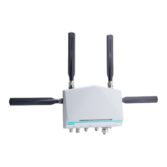
Dimensions Unit = mm (inch) Attaching Antennas The AWK-6232-M12 inclues two dual-band omnidirectional antenna by default. Attach the antennas as illustrated below. Rubber plate Antenna Metal N-type Step 1: Use your fingers and hold the antenna metal N-type connector. Step 2: Screw the antenna N-type connector (male) onto the AWK-6232-M12 device’s N-type connector (female) Caution Do not hold the rubber plate to screw the antenna on to the... -
Page 6: Wall Mounting
Wall Mounting In most applications, wall mount provides an easier installation. You will find it quite easy to mount AWK-6232-M12 on the wall, as illustrated below. STEP 1: STEP 2: Attach the wall-mounting kit Mounting the AWK-6232-M12 on the with M4 screws, as shown in wall requires 4 screws. -
Page 7: Din-Rail Mounting (Optional)
DIN-Rail Mounting (Optional) The DK-DC50131 die-cast metal kit can be bought separately, and enable easy and robust installation for the AWK-6232-M12. A pair of DK-DC50131s is needed for DIN-Rail mounting. To install the DIN-Rail mounting kits, tightly attach the two DIN-Rail mounting kits on the rear panel of AWK-6232-M12 with 12 screws. -
Page 8: Wiring Requirements
Wiring Requirements WARNING Safety First! Be sure to disconnect the power cord before installing and/or wiring your Moxa AWK-6232-M12. Calculate the maximum possible current in each power wire and common wire. Observe all electrical codes dictating the maximum current allowable for each wire size. If the current goes above the maximum ratings, the wiring could overheat, causing serious damage to your equipment. -
Page 9: Wiring The Redundant Power Inputs
Wiring the Redundant Power Inputs The AWK-6232-M12 must be connected to a Power over Ethernet Plus (PoE+) IEEE 802.3at compliant power source or an IEC60950 compliant limited power source. When AWK-6232-M12 is powered via DC power, the M12 A-coding connector on the bottom panel is used for the AWK-6232-M12’s two redundant inputs. - Page 10 Signal Relay DI1 I1 DI1 COM_1 DI2 I2 DI2 COM_2 Reserved Communication Connections Connecting the Data Lines 10/100/1000BaseT(X) Ethernet Port Connection AWK-6232-M12 has 10/100/1000BaseT(X) Ethernet ports (8-pin shielded M12 connector with A coding). The 10/100/1000BaseT(X) ports located on the AWK-6232-M12’s bottom panel are used to connect to Ethernet-enabled devices.
- Page 11 ATTENTION To ensure the IP68-rated connectivity, you must use a waterproof housing during any communication activities. An IP68-rated field installable plug, which is attached in AWK-6232-M12’s accessory pack, may be needed in this case. The installation guide is shown below: Ethernet M12 Plug Dimensions (unit: mm) Installation...
-
Page 12: Led Indicators
NOTE 1. The pin numbers for male DB9 and DB25 connectors, and hole numbers for female DB9 and DB25 connectors are labeled on the connector. However, the numbers are typically quite small, so you may need to use a magnifying glass to see the numbers clearly. -
Page 13: Specifications
Color State Description Amber, The 10/100Mbps link on the device’s LAN port is active Amber, Device is transmitting LAN data at 10/100 blinking Mbps Amber, 10/100Mbps LAN port link is inactive LAN 1 Amber/ Green Green, LAN 2 1000Mbps LAN port link is active Green, Device is transmitting LAN data at 1000 blinking... - Page 14 TX Transmit Power: 802.11b: 1 to 11 Mbps: Typ. 18 dBm (± 1.5 dBm) 802.11g: 6 to 24 Mbps: Typ. 18 dBm (± 1.5 dBm) 36 to 48 Mbps: Typ. 17 dBm (± 1.5 dBm) 54 Mbps: Typ. 15 dBm (± 1.5 dBm) 802.11a: 6 to 24 Mbps: Typ.
-
Page 15: Physical Characteristics
Physical Characteristics Housing: Metal, IP68 protection Weight: 1.8 kg Dimensions: 224 x 147.7 x 64.5 mm (8.82 x 5.82 x 2.54 in) Installation: Wall mounting (standard), DIN-Rail mounting (optional), pole mounting (optional) Environmental Limits Operating -40 to 75°C (-40 to 167°F) Temperature: Storage -40 to 85°C (-40 to 185°F) - Page 16 ATTENTION This device complies with part 15 of the FCC Rules. Operation is subject to the following two conditions: 1. This device may not cause harmful interference, and 2. This device must accept any interference received, including interference that may cause undesired operation. ATTENTION Do not locate the antenna near overhead power lines or other electric light or power circuits, or where it can come into contact...
Need help?
Do you have a question about the AirWorksAWK-6232-M12 and is the answer not in the manual?
Questions and answers