Table of Contents
Advertisement
Quick Links
INSTALLER AND OWNER GUIDE
Please keep me in a safe place for future use.
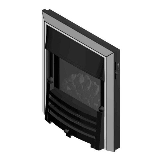
Model 963
Inset live fuel effect gas fire
Fitted with the
(G.C. Number 32-032-92)
We trust that this guide gives sufficient details to enable this appliance to be
installed, operated and maintained satisfactorily. However, if further information is
required, our Wonderfire Premier Technical Helpline will be pleased to help.
Telephone 0844 879 35 88 (National call rates apply in the United Kingdom).
In the Republic of Ireland Telephone 01 842 8222.
©
GDC Group Ltd. 2012
Bauhaus
fascia.
5140182/02
Advertisement
Chapters
Table of Contents

Related Manuals for Wonderfire 963

Summary of Contents for Wonderfire 963
- Page 1 We trust that this guide gives sufficient details to enable this appliance to be installed, operated and maintained satisfactorily. However, if further information is required, our Wonderfire Premier Technical Helpline will be pleased to help. Telephone 0844 879 35 88 (National call rates apply in the United Kingdom).
- Page 2 Warning: Any person who does any unauthorised act in relation to a copyright work may be liable to criminal prosecution and civil claims for damages. www.wonderfire.co.uk Because our policy is one of constant development and improvement, details may vary slightly from those given in this publication ©...
- Page 3 BS EN ISO 9001 quality system accepted by the British Standards Institute. The Highest Standards Wonderfire is a member of SBGI and HHIC (Heating and Hot water Industry Council) that work to ensure high standards of safety, quality and performance. Careful Installation...
-
Page 4: Installer Guide
INSTALLER GUIDE INSTALLER GUIDE FOR OWNER GUIDE SEE PAGES 45 TO 63 © Page 4 GDC Group Ltd. 2012... -
Page 5: Table Of Contents
INSTALLER GUIDE CONTENTS Section Heading Page INSTALLER GUIDE 4 - 44 OWNER GUIDE 45 - 63 1. IMAGE 2. SAFETY AND UNPACKING 3. APPLIANCE DATA, EFFICIENCY AND NOx 3.1 General information. 3.2 Efficiency. 3.3 NOx 4. GENERAL INSTALLATION REQUIREMENTS 4.1 Regulations, Standards and Law. 4.2 Ventilation requirements. - Page 6 INSTALLER GUIDE CONTENTS (Continued) Section Heading Page 10. CONVECTION BOX INSTALLATION 10.1 Method 1- Front fixing to fireplace surround. 10.2 Method 2 - Cable retention. 10.3 Floor sealing. 10.4 Sealing convection box holes. 11. BURNER AND SUPPLY PIPE INSTALLATION 11.1 Burner and supply pipe installation. 11.2 Preliminary burner checks.
-
Page 7: Image
INSTALLER GUIDE 1. IMAGE © Page 7 GDC Group Ltd. 2012... -
Page 8: Safety And Unpacking
INSTALLER GUIDE 2. SAFETY AND UNPACKING Installer Before continuing any further with the installation of this appliance please read the following guide to manual handling. The approximate lifting weight (kg) of this appliance is as below: Heat Engine Firefront and ash pan Fascia Combined Weight 11.28... -
Page 9: Appliance Data, Efficiency And Nox
INSTALLER GUIDE 3. APPLIANCE DATA, EFFICIENCY AND NO 3.1 General information. Natural (G20) Inlet Pressure 20mbar Input - Max. (Gross) 3.9kW (13,307 Btu/h) Input - Min. (Gross) 2.3kW (7,848 Btu/h) Input - Max. (Net) 3.51kW (11,976 Btu/h) Input - Min. (Net) 2.07kW (7,062 Btu/h) Inlet Test Pressure (Cold) 20.0 ±... -
Page 10: Efficiency
INSTALLER GUIDE 3.2 Efficiency. The efficiency of this appliance has been measured as specified in BS 7977 - 1 and the result is as below: Model Efficiency % (Gross) Efficiency % (Net) The gross calorific value of the fuel has been used for this efficiency calculation. The test data from which it has been calculated has been certified by BSI (0086). -
Page 11: General Installation Requirements
INSTALLER GUIDE 4. GENERAL INSTALLATION REQUIREMENTS 4.1 Regulations, Standards and Law. The installation must be in accordance with these instructions. For the user’s protection, in the United Kingdom it is the law that all gas appliances are installed by competent persons in accordance with the current edition of the Gas Safety (Installation and Use) Regulations. -
Page 12: Ventilation Requirements
INSTALLER GUIDE 4.2 Ventilation requirements. Normal adventitious ventilation is usually sufficient to satisfy the ventilation requirements of this appliance. In GB reference should be made to BS 5871 Part 2 and in IE reference should be made to the current edition of IS 813 “Domestic Gas Installations”... -
Page 13: Fireplace Preparation
INSTALLER GUIDE 4.7 Fireplace preparation. 4.7.1 If the fireplace opening is an underfloor draught type, it must be sealed to stop any draughts. 4.7.2 The fireplace floor should be reasonably flat to ensure that the convection box can be installed without it rocking and so that a good seal can be made at the bottom front of the box. -
Page 14: Fireplace Clearances
INSTALLER GUIDE 4.9 Fireplace clearances. 4.9.1 The minimum height from the base of the fireplace opening to the underside of any shelf made from wood or other combustible materials is detailed below. • For a shelf up to 150mm deep: Minimum height = 700mm. •... - Page 15 INSTALLER GUIDE 4.9.2 The minimum allowable distance from the outside of the appliance fascia to a corner wall having combustible material or any other combustible surface which projects beyond the front of the appliance is shown in figure 4. A 10mm access clearance from a non-combustible surface is necessary at the left side.
-
Page 16: Installation Options
INSTALLER GUIDE 4.10 Installation options. In the United Kingdom, as supplied, the appliance can be installed in the following situations: - 4.10.1 Conventional fireplace and hearth. To a fireplace complete with hearth as shown in figure 5. Chair brick removal may not be required providing at least 50mm clearance is available from the flue outlet to any fireplace component. - Page 17 INSTALLER GUIDE 4.10.2 Metal flue box and hearth. The appliance can be installed to a fireplace incorporating a twin wall metal flue box complying with the constructional requirements of the current edition of BS 715 and with a flue conforming to BS EN 1856 part 1. The dimensions of the flue box must conform to those shown in figure 6.
- Page 18 INSTALLER GUIDE 4.10.3 Precast concrete or clay flue block system and hearth. The appliance can be installed to a precast concrete or clay flue block system conforming to BS1289 or BS EN 1858 with dimensions as in figure 7. BS 1289 part 1 recommends there should be an air space or insulation between the flue blocks and the plaster because heat transfer may cause cracking on directly plastered flues.
-
Page 19: Flues
INSTALLER GUIDE 4.11 Flues. 1. Suitable flues and minimum flue sizes are as follows: It should be noted that, as with many appliances, sharp bends or horizontal runs in metal flues at the top of the system can be a cause of problems in these types of installation. -
Page 20: Pack Contents
INSTALLER GUIDE 5. PACK CONTENTS The items required for this appliance are packed in sections. Pack 1 - Fire unit contains: 1 Heat engine. 1 Hood 1 Loose parts pack including: - 1 Grommet for rear of convection box. 2 Strips of floor sealing tape. 6 Fibre / wooden plugs. - Page 21 INSTALLER GUIDE Figure 8. Pack one contents (Continued on next page) © Page 21 GDC Group Ltd. 2012...
-
Page 22: Fireplace Check
INSTALLER GUIDE Figure 8. Pack two contents 6. FIREPLACE CHECK 6.1 Soundness for appliance attachment. Two primary methods of retaining the appliance are provided: - 1) By fixing to the fireplace front surround. 2) Using concealed fire retaining cables fixed to the rear of the fireplace opening together with secondary fixing to the fireplace floor. -
Page 23: Ignition Check
INSTALLER GUIDE Observe where possible, upstairs rooms and loft spaces for signs of escaping smoke indicating a defective flue. If there is not a definite flow, warm the flue for a few minutes and repeat the smoke pellet test. If there is still no definite flow the flue may need remedial work –... -
Page 24: Gas Supply Connection
INSTALLER GUIDE Concealed supply pipe connection. If a concealed connection from inside the fireplace is required then, before the appliance is fitted into the fireplace it will be necessary to extend the supply line so that it will project through the hole in the back of the convection box and run to the inlet ‘T’... -
Page 25: Fitting The Foam Seal
INSTALLER GUIDE 5. It is important that the grommet supplied in the loose parts pack is fitted to the hole in the rear of the convection box (See figure 15). 9.2 Fitting the foam seal. There is a length of self adhesive foam seal supplied with the fire. -
Page 26: The Flue Restrictor
INSTALLER GUIDE 9.3 The flue restrictor. This appliance is fitted with a flue restrictor for use where the flue draught is excessive. The flue restrictor can be adjusted from the front of the fire so there is no need to remove the fire from the fireplace for adjustment to be made. Generally we recommend the restrictor is set to its fully open position where a precast flue, metal flue box or a flue liner is used, however, certain flues may work sufficiently to warrant its use. -
Page 27: Convection Box Installation
INSTALLER GUIDE 10. CONVECTION BOX INSTALLATION 10.1 Method 1- Front fixing to fireplace surround. 1. Make sure that the fireplace front surround area is sound enough to take the fibre / wooden plugs and wood screws. If necessary, make sound with suitable cement. - Page 28 INSTALLER GUIDE fireplace to ensure that the appliance finishes centrally in the opening when tension is applied to the cables. 3. Insert a fibre / wooden plug into each hole. Use the fibre / wooden plugs supplied with this appliance - Never use plastic plugs instead of the fibre / wooden plugs supplied.
-
Page 29: Floor Sealing
INSTALLER GUIDE 9. Insert a fibre / wooden plug into each hole. Use the fibre / wooden plugs supplied with this appliance - Never use plastic plugs instead of the fibre / wooden plugs supplied. Fit a wood screw in each plug and tighten. -
Page 30: Burner And Supply Pipe Installation
INSTALLER GUIDE 11. BURNER AND SUPPLY PIPE INSTALLATION 11.1 Burner and supply pipe installation. 1. Fit the burner unit to the convection box with two screws (See figure 14). 2. Align the hole near the bottom of the control linking bar with that in the control pivot bracket. -
Page 31: Inlet Pressure Check
INSTALLER GUIDE 11.3 Inlet pressure check. The appliance is pre-set to give the correct heat input at the inlet pressure shown in section 3 of this manual. No adjustment is necessary. 1. Check the inlet pressure by fitting a pressure gauge at the test point. -
Page 32: Spillage And Flame Supervision Checks
INSTALLER GUIDE 14. SPILLAGE AND FLAME SUPERVISION CHECKS 14.1 Check for spillage. A spillage check must be made before leaving the installed appliance with the customer. Make this with all the ceramic fuel effect pieces and window in position. IMPORTANT: Only use the smoke match tube supplied with the fire. Do NOT use other smoke match tubes. -
Page 33: Flame Supervision And Spillage Monitoring System
INSTALLER GUIDE 7. If the above test is satisfactory, open all internal connecting doors, hatches, etc., in the room. Keep all doors and windows that open to the outside of the building closed. Recheck for spillage as above. If an extractor fan is installed in the same room as the appliance or a connecting room, check that spillage does not occur with the fan operating and all doors and other openings between the fan and the appliance open. -
Page 34: Fitting The Heat Baffle
INSTALLER GUIDE 15. FITTING THE HEAT BAFFLE 1. The fire is supplied with a heat baffle. Locate the heat baffle to the top of the fire as shown in figure 27. Figure 27. 16. FITTING THE FASCIA 1. Locate the hanging brackets on the rear of the fascia onto the support bar at the top of the fire (See figure 28). -
Page 35: Firefront Casting Installation
INSTALLER GUIDE 2. Secure the bottom of the fascia unit to the convection box with two M4 x 25mm screws and washers (See figure 29). Figure 29. 17. FIREFRONT CASTING INSTALLATION 1. The assembly instructions are contained in the fascia pack. 2. -
Page 36: Lighting The Burner
INSTALLER GUIDE 18.2 Lighting the burner. 1. Make sure the slider knob is at the ‘OFF’ position. 2. Slide the knob to the bottom (ignition) position marked . Retain in this position to ignite the pilot. The burner should ignite at its lowest setting within 4 seconds of the pilot igniting. -
Page 37: Final Review
INSTALLER GUIDE 19. FINAL REVIEW 1. COMPLETE THE INFORMATION IN THE WARRANTY AND SERVICE SECTION OF THE OWNER GUIDE (See last pages of the OWNER guide). 2. Visually inspect the appliance. Clean off any marks incurred during installation. 3. Advise the customer how to operate the fire. 4. -
Page 38: Servicing & Parts Replacement
INSTALLER GUIDE 20. SERVICING & PARTS REPLACEMENT Always turn off the gas supply and allow to cool completely before commencing any servicing (The appliance inlet “T” connector incorporates an isolating valve). It is recommended that, at least once a year, the appliance is disconnected and the fireplace opening checked and cleared of any debris. -
Page 39: Checking The Aeration Setting Of The Burner
INSTALLER GUIDE 20.1 Checking the aeration setting of the burner. 1. The aeration shutter is factory set. It is important to ensure that the aeration setting is correct (See figure 31). 2. To adjust the aeration setting loosen the two aeration shutter screws, slide the aeration shutter to the desired position and tighten the fixing screws. -
Page 40: To Remove The Fascia
INSTALLER GUIDE 20.4 To remove the fascia. 1. Remove the firefront casting and the front cover casting. 2. Remove the two screws and washers securing the bottom of the fascia to the sides of the convection box. 3. Carefully lift the fascia upward to clear the upper support bracket on the convection box (See figure 34). -
Page 41: To Replace The Control Slide Knob
INSTALLER GUIDE 7. Replace in the reverse order (When fitting the screw that connects the control slider to the burner use a screwdriver - do not leave as finger tight only). 20.7 To replace the control slide knob. 1. Remove the fascia (See section 20.4) 2. -
Page 42: To Remove The Pilot Unit
INSTALLER GUIDE 20.10 To remove the pilot unit. 1. Remove the burner unit (See section 20.6). 2. Detach the pilot pipe from the pilot unit. 3. Detach the thermocouple from the interrupter block by unscrewing the thermocouple nut. 4. Detach the electrode lead from the underside of the electrode tab. -
Page 43: To Remove The Gas Flow Rate Controller
INSTALLER GUIDE must have a constant working temperature of at least 80°C). When refitting, make sure that the tap spindle is in the correct relationship relative to the control pivot bracket. Rotate the pivot bracket fully clockwise. The tap spindle should “bottom out” (i.e. -
Page 44: To Remove The Main Burner Injector
INSTALLER GUIDE 5. Lift the right hand side of the burner, slide it to the right and lift clear. 6. Refit in reverse order. 20.14 To remove the main burner injector. 1. Remove the burner (See section 20.13, paragraphs 1-4). 2. -
Page 45: Owner Guide
OWNER GUIDE OWNER GUIDE FOR WARRANTY AND SERVICE INFORMATION SEE PAGES 57 TO 63 © Page 45 GDC Group Ltd. 2012... - Page 46 OWNER GUIDE LIST OF CONTENTS Section Page IMAGE SAFETY GAS CONSUMPTION APPLIANCE DIMENSIONS OPERATING YOUR FIRE The Oxysafe flame sensing and flue blockage safety system. Lighting the pilot. Lighting with a taper. HELP AND ADVICE Ignition - Lighting the fire. Glass - Window and rear firebox panel.
-
Page 47: Image
OWNER GUIDE IMAGE © Page 47 GDC Group Ltd. 2012... -
Page 48: Safety
OWNER GUIDE SAFETY IF YOU SMELL GAS - DON’T SMOKE. - EXTINGUISH ALL NAKED FLAMES. - DON’T TURN ELECTRICAL SWITCHES ON OR OFF. - TURN OFF THE GAS SUPPLY AT THE METER. - OPEN DOORS AND WINDOWS TO GET RID OF THE GAS. - IMMEDIATELY CALL THE GAS EMERGENCY SERVICE FROM A NEIGHBOURS PHONE - SEE YOUR LOCAL TELEPHONE DIRECTORY. -
Page 49: Gas Consumption
OWNER GUIDE Do wait three minutes before attempting to relight if the fire is switched off or the flames are extinguished for any reason (Your fire is fitted with a safety device that will automatically shut off the gas supply to the fire, if for any reason, the flame goes out). Do get advice about the suitability of any wall covering near your fire. -
Page 50: Appliance Dimensions
OWNER GUIDE APPLIANCE DIMENSIONS Model Description Bauhaus Height (mm) Width (mm) Depth into room (mm) Minimum mandatory clearance to combustible surfaces projecting beyond the front of appliance (mm). Recommended clearance to non-combustible surfaces for access purposes (mm). Figure 2. (Dimensions are subject to manufacturing tolerances) ©... -
Page 51: Operating Your Fire
These vapours are quite normal with new appliances. They are totally harmless and will disappear after a few hours use. Wonderfire Premier considers all surfaces as working surfaces (which means they get hot) with the exception of those areas intended to be touched by the owner during normal use. -
Page 52: Lighting With A Taper
OWNER GUIDE Keep the knob at the ignition position for a further ten seconds. This will prevent the flame sensing device from shutting off the gas while its probe warms up as explained above. If low heat is required, release the knob. The knob will automatically spring up to the low heat position shown in figure 3 (See note i). -
Page 53: Help And Advice
OWNER GUIDE HELP AND ADVICE Ignition - Lighting the fire. When you depress the Fireslide control you should hear a faint ticking sound from the bottom of the fire. This is the sound of the ignition spark that lights the gas. If there is no ticking sound it may be that the battery in the electronic spark generator requires replacement. -
Page 54: Cleaning Your Fire
OWNER GUIDE CLEANING YOUR FIRE To maintain the high performance and quality finish of your Wonderfire Premier appliance, please follow these guidelines: Before attempting to clean the fire, please remember to turn off the fire and wait for the appliance to cool completely. The fire will retain heat for some time before cleaning can begin. -
Page 55: Ceramic Fuel Effect
OWNER GUIDE Ceramic fuel effect. This product uses fuel effect pieces containing Refractory Ceramic Fibres (RCF), which are man-made vitreous silicate fibres. Excessive exposure to this material may cause irritation to eyes, skin and respiratory tract. Consequently, it is important to take care when handling these articles to ensure that the release of dust is kept to a minimum. -
Page 56: Ceramic Fuel Effect Refitting
OWNER GUIDE CERAMIC FUEL EFFECT REFITTING The installer and owner guide for the ceramic fuel effect is separate from this guide. The installer may have attached it to this guide or placed it inside. It is important that the installer and owner guide for the ceramic fuel effect is followed correctly. If replacing the ceramic fuel effect, where a new guide is supplied, follow the installer and owner guide supplied with the replacement fuel effect. -
Page 57: Replacement Ceramics
If you did not receive a Warranty Booklet please contact your retailer where you purchased the fire. Please note the warranty is for Wonderfire Premier Fires only. If you have not registered your fire you are entitled to the standard 12 months warranty subject to contract. - Page 58 The warranty period will be 60 calendar months from the date of purchase. The first 12 months are covered by the standard manufacturers guarantee. 10. During the 48 month warranty period Wonderfire Premier will exchange or repair component[s] proved to be faulty from manufacture provided that such component[s] have been subject to normal conditions of use.
- Page 59 22. Call out charges where faults are excluded from the warranty. 23. Faults caused by inadequate supply of gas or electricity (where applicable) 24. Wonderfire is not responsible for any damage caused by a third party. 25. Compensation or consequential losses (e.g. loss of earnings, business losses, stress and inconvenience) arising from a product breakdown, including repair delays caused by factors outside of our reasonable control.
- Page 60 OWNER GUIDE © Page 60 GDC Group Ltd. 2012...
- Page 61 OWNER GUIDE © Page 61 GDC Group Ltd. 2012...
- Page 62 OWNER GUIDE The following pages are to be completed by the installer: Installer Details (Block Capitals) Installer Name Gas Safe Register Number. Company Name. Company Address Company Telephone number Company Fax number Where to find the information label. Figure 7. ©...
- Page 63 OWNER GUIDE Serial number (A label containing this information may have been placed below or can be found on the serial number label - See figure 7) A LABEL CONTAINING THE SERIAL NUMBER MAY HAVE BEEN PLACED INSIDE THIS BOX. SERIAL NUMBER LABEL TO BE AFFIXED HERE Fascia name...
- Page 64 © GDC Group Ltd. 2012...
Need help?
Do you have a question about the 963 and is the answer not in the manual?
Questions and answers