Table of Contents
Advertisement
Quick Links
Advertisement
Table of Contents

Subscribe to Our Youtube Channel
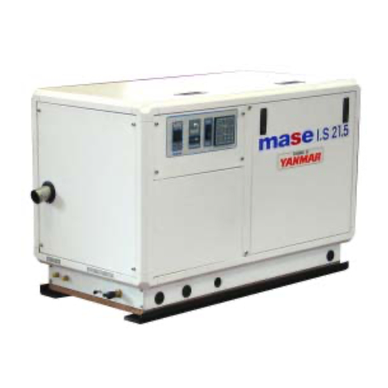
Summary of Contents for Mase I.S. 21.5
- Page 1 I.S. 21.5 60 Hz 50 Hz I.S. 23.5 60 Hz 60 Hz GB - INSTALLATION MANUAL...
- Page 2 IS 21.5-23.5 GENERATORS Fig. 1 Fig. 2 Fig. 3 Fig. 4 - 2 -...
- Page 3 IS 21.5-23.5 GENERATORS Fig. 5 Fig. 6 Fig. 7 Valvola antisifone Anti-siphon valve Soupape antisiphon Beluchter Fig. 8 Fig. 9 - 3 -...
- Page 4 IS 21.5-23.5 GENERATORS Fig.10 Fig.11 Fig.12 Fig.13 - 4 -...
- Page 5 IS 21.5-23.5 GENERATORS RETE GEN. MAINS RESEAU WALAANSL CARICO LOAD CHARGE VERBRUIKERS Fig.15 Fig.14 - 5 -...
-
Page 6: Wiring Diagram
IS 21.5-23.5 GENERATORS WIRING DIAGRAM Fig.16 - 6 -... - Page 7 IS 21.5-23.5 GENERATORS INDEX Pictures ........................... 2 Wiring diagram ........................7 GENERAL INFORMATION ....................14 Purpose and field of application of the manual ..............14 Symbols .......................... 14 Prescriptions for safety during installation and setup ..........15 INSTALLATION ......................15 Characteristics of the installation space ................
-
Page 8: General Information
MANUAL WILL RESULT IN FORFEITURE OF THE GUARANTEE ON THE PRODUCT 1.1 Purpose and field of application of the manual Thank you for choosing a mase product. This manual has been drawn up by the manufacturer with the purpose of providing essential information and instructions for proper installation in conditions of safety and constitutes an integral part of the generator equipment. -
Page 9: Prescriptions For Safety During Installation And Setup
2 - System with baffle near electric equipment (including lamps) or parts MASE recommends the direct infeed system (ref.1 fig. 3) of the electrical system. since this system prevents water under pressure enter-... - Page 10 IS 21.5-23.5 GENERATORS 4.2.2 Typical installation with generator below the The filter mesh should be very fine. water line (Fig.5) Mesh 2 - 470 micron is recommended, other sizes do Sea exhaust not give good filter performance. Silencer Muffler 5 - Anti-siphon valve: this is a valve that brings the Water filter cooling circuit back to atmospheric pressure when Main system tap...
-
Page 11: Fuel Circuit
IS 21.5-23.5 GENERATORS 5 FUEL CIRCUIT Control panel connection There are two remote control panels available, installable The unit is fed by diesel fuel through the tubes marked on the bridge, which can be connected to the generator for “Fuel inlet”(fig.10 ref.2 ) and “fuel outlet” (fig.10 ref.3). starting and stopping. - Page 12 IS 21.5-23.5 GENERATORS Table of characteristics for single voltage 8 WIRING DIAGRAM REFERENCES See Fig.16 1 - Magnetothermal switch 156.5 2 - Hour counter IS 21.5 78.2 3 - Alternator 4 - Rotor IS 23.5 87.5 5 - Stator 6 - Voltage regulator 7 - Power terminal board Table of characteristics for double voltage 8 - /...


Need help?
Do you have a question about the I.S. 21.5 and is the answer not in the manual?
Questions and answers