Monessen Hearth BDV300 Installation And Operating Instructions Manual
Bdv series
direct vent gas fireplace
Hide thumbs
Also See for BDV300:
- Installation and operating instructions manual (68 pages) ,
- Instruction manual (64 pages) ,
- Installation and operating instructions manual (52 pages)
Table of Contents
Advertisement
DIRECT VENT GAS FIREPLACE
INSTALLATION AND OPERATING INSTRUCTIONS
WARNINGS
IFTHE INFORMATION INTHESE INSTRUCTIONS ARE
NOT FOLLOWED EXACTLY, A FIRE OR EXPLOSION
MAY RESULT CAUSING PROPERTY DAMAGE,
PERSONAL INJURY OR LOSS OF LIFE.
–
Do not store or use gasoline or other flammable
vapors and liquids in the vicinity of this or any
other appliance.
–
WHAT TO DO IF YOU SMELL GAS
• Do not try to light any appliance.
• Do not touch any electrical switch; do not use
any phone in your building.
• Immediately call your gas supplier from a
neighbor's phone. Follow the gas supplier's
instructions.
• If you cannot reach your gas supplier, call the
fire department.
–
Installation and service must be performed
by a qualified installer, service agency or the
gas supplier.
WARNING: Improper installation, adjustment,
alteration,services or maintenance can cause injury or
property damage. Refer to this manual. For assistance
or additional information consult a qualified installer,
service agency or the gas supplier.
This appliance is only for use with the type of gas
indicated on the rating plate. This appliance is
not convertible for use with other gases, unless a
certified kit is used.
This appliance may be installed in an aftermarket*,
permanently located, manufactured home, where not
prohibited by local codes.
*Aftermarket: Completion of sale, not for purpose of resale, from
the manufacturer.
READ BEFORE INSTALLING. SAVE THESE INSTRUCTIONS
BDV SERIES
MODELS:
BDV300, BDV400,
BDV500, BDV600
DUE TO HIGH TEMPERATURES, THE
APPLIANCE SHOULD BE LOCATED
OUT OF TRAFFIC AND AWAY FROM
FURNITURE AND DRAPERIES.
CHILDREN AND ADULTS SHOULD BE
ALERTED TO THE HAZARDS OF HIGH
SURFACE TEMPERATURE AND SHOULD
STAY AWAY TO AVOID BURNS OR
CLOTHING IGNITION.
YOUNG
CHILDREN
SUPERVISED WHEN THEY ARE IN THE
SAME ROOM AS THE APPLIANCE.
CLOTHING OR OTHER FLAMMABLE
MATERIAL SHOULD NOT BE PLACED
ON OR NEAR THE APPLIANCE.
KEEP THE ROOM AREA CLEAR AND
FREE FROM COMBUSTIBLE MATERIALS,
GASOLINE, AND OTHER FLAMMABLE
VAPORS AND LIQUIDS.
SHOULD
BE
Advertisement
Table of Contents

Related Manuals for Monessen Hearth BDV300


Summary of Contents for Monessen Hearth BDV300
-
Page 1: Installation And Operating Instructions
BDV SERIES DIRECT VENT GAS FIREPLACE INSTALLATION AND OPERATING INSTRUCTIONS MODELS: BDV300, BDV400, BDV500, BDV600 WARNINGS IFTHE INFORMATION INTHESE INSTRUCTIONS ARE NOT FOLLOWED EXACTLY, A FIRE OR EXPLOSION MAY RESULT CAUSING PROPERTY DAMAGE, PERSONAL INJURY OR LOSS OF LIFE. –... -
Page 2: Table Of Contents
CONTENTS Important Safety Information ......3 Electrical Installation ........29 Electrical Wiring .......... 29 Product Features ..........5 Remote Wall Switch ........29 Code Approval ..........5 Glass Removal..........30 Pre-Installation Information Final Installation ..........31 Installing Above 2000 Feet......6 Rockwool Placement ........ -
Page 3: Important Safety Information
IMPORTANT SAFETY INFORMATION INSTALLER OWNER Please leave these instructions with the owner. Please retain these instructions for future reference. • Read this owner’s manual carefully and completely before trying to assemble, operate, or service this fireplace. • Any change to this fireplace or its controls can be dangerous. •... - Page 4 IMPORTANT SAFETY INFORMATION Continued from page 3 IMPORTANT: 12. Do not use this fireplace to cook food or burn paper or PLEASE READ THE FOLLOWING CAREFULLY other objects. It is normal for fireplaces fabricated of steel to give off some expansion and/or contraction noises 13.
-
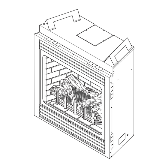
Page 5: Product Features
Receiver tions and was determined independently of any installed system. Figure 1 - BDV300, 400, 500, 600 Fireplace Thermal Efficiency = up to 80% CODE APPROVAL Direct Vent type appliances draw all combustion air from outside of the dwelling through the vent pipe. -
Page 6: Pre-Installation Information
Manifold Press: (W.C.) 3.5" Manifold Press: (W.C.) 10" Maximum Supply Pressure 10.5" Maximum Supply Pressure 13" Minimum Supply Pressure 4.5" Minimum Supply Pressure 11" Model Number BDV300 BDV400 BDV500 BDV600 Natural Propane Natural Propane Natural Propane Natural Propane Max. Btu/hr Input... -
Page 7: Fireplace Framing
FIREPLACE FRAMING Firebox framing can be built before or after the appliance is set in place. Construct firebox framing following Figure 2 and the chart below for your specific installation requirements. See Figure 3 on Page 8 for firebox dimensions. The framing headers may rest on the top of the firebox standoffs. -
Page 8: Fireplace Dimensions
� � � � � � � � � � � � � Figure 3 - Fireplace Dimensions DESCRIPTION Key Letter BDV300 BDV400 BDV500 BDV600 Overall Front Width " " " " Inside Width " 32" 36" 42" Glass Width 27"... -
Page 9: Fireplace Location
PRE-INSTALLATION INFORMATION FIREPLACE LOCATION Plan for the installation of your appliance. This includes determining where the unit is to be installed, the vent configuration to be used, framing and finishing details, and whether any optional accessories (i.e. blower, wall switch, or remote control) are desired. -
Page 10: Clearances
SECURING FIREPLACE TO FLOOR OR FRAMING The fireplace must be secured to the floor and/or to framing studs as shown in Figure 5. Use two (2) wood screws or masonry/ concrete screws to secure fireplace to the floor. Use four (4) screws to attach fireplace to framing. The side brackets are adjustable from 1/2"... - Page 11 CLEARANCES CLEARANCES TO COMBUSTIBLES Follow these instructions carefully to ensure safe installation. Failure to follow instructions exactly can create a fire hazard. The appliance cannot be installed on a carpet, tile or other combustible material other than wood flooring. If installed on carpet or vinyl flooring, the appliance shall be installed on a metal, wood or noncombustible material panel extending full width and depth of the appliance.
-
Page 12: Installation Information
INSTALLATION INFORMATION FINISHING MATERIAL NOTE: Any remote wiring (i.e. remote control, wall switch, and optional fan) must be done prior to final finishing to avoid costly reconstruction. Never obstruct or modify the air inlet or outlet grills (louvers). This may create a fire hazard. - Page 13 VENT INSTALLATION This fireplace must be vented to the outside. The venting system must NEVER be attached to a chimney serving a separate solid fuel burning appliance. Each gas appliance must use a separate vent system. Do not use common vent systems. A Minimum of 3"...
-
Page 14: Optional Top Vent Application
VENT INSTALLATION OPTIONAL TOP VENT APPLICATION After conversion vent The appliance is shipped as a rear vent unit. If the installation configuration the 4" (100mm) flue pipe layout requires the unit to be a top vent configuration the appli- ance can be converted by following the steps below. should be concentric within the 6 "... -
Page 15: Installation Planning
VENT INSTALLATION INSTALLATION PLANNING There are two basic types of direct-vent installation: • Horizontal Termination • Vertical Termination It is important to select the proper length of vent pipe for the type of termination you choose. It is also important to note the wall thickness. - Page 16 VENT INSTALLATION FOR HORIZONTAL TERMINATION Inside Corner Detail � � � � � � � � � � � � � ����� � � ������ ������ ����� � ��� ������ � � �������� � � � � � � � �...
-
Page 17: How To Use The Vent Graph
VENT INSTALLATION TERMINATION CLEARANCES FOR BUILDINGS WITH COMBUSTIBLE AND NONCOMBUSTIBLE EXTERIORS � � � ���� ������� � � � � � ���� ������� ������ ������ ������� ������ � � ������� ����� �� ��� �������� � ��� ������ �������� � � ������� ����� ��� ���� ���� �� �... -
Page 18: Rear Wall Vent Installation
VENTING INSTALLATION REAR WALL VENT INSTALLATION When installed as a rear vent unit this appliance may be vented directly to a termination located on the rear wall behind the appliance • The maximum horizontal distance between the rear of the appliance and the outside of termination is 20" (508 m). See Figure 14. - Page 19 VENT INSTALLATION Deflecting Shield REAR WALL VENT INSTALLATION (continued) 4. Apply a bead of non-hardening mastic around the outside edge of vent cap. Position the vent cap in the center of hole on the exterior wall with the word “UP” on the vent cap facing up.
-
Page 20: Horizontal Termination Configuration
VENT INSTALLATION HORIZONTAL TERMINATION CONFIGURATIONS Since it is very important that the venting system maintain its balance between the combustion air intake and the flue gas exhaust, certain limitations as to vent configurations apply and must be strictly adhered to. The Vent Graph, showing the relationship between vertical and horizontal side wall venting, will help to determine the vari- ous dimensions allowable. -
Page 21: Horizontal Termination Configuration
VENT INSTALLATION HORIZONTAL TERMINATION CONFIGURATION 90° (Continued) • If a 90° elbow is used in the horizontal vent run (level height maintained) the horizontal vent length is reduced by 36" (914 mm) (Fig. 21 A and B) This does not apply if the 90° elbows are used to increase or redirect a vertical rise. -
Page 22: Below Grade Installation
VENT INSTALLATION BELOW GRADE INSTALLATIONS When it is not possible to meet the required vent terminal clearances of 12" above grade level, a snorkel kit is recommended. It allows installation depth down to 7" (178mm) below grade level. The 7" (178mm) is measured from the center of the horizontal vent pipe as it penetrates through the wall. -
Page 23: Vertical Through-The-Roof Installation
VENT INSTALLATION VERTICAL THROUGH-THE-ROOF APPLICATIONS This Gas Fireplace has been approved for, • Vertical installations up to 40' (12m) in height. Up to a 10' (3m) horizontal vent run can be installed within the vent system using a maximum of two 90° elbows. See Figure 27. Support Straps Every... -
Page 24: Cathedral Ceiling Installation
VENT INSTALLATION INSTALLATION FOR VERTICAL TERMINATION 1. Determine the route your vertical venting will take. If ceiling joist, Roof roof rafters or other framing will obstruct the venting system, Flashing consider an offset. See Figure 29 to avoid cutting load bearing members. - Page 25 VENT INSTALLATION 4. Connect a section of pipe and extend up through the hole. NOTE: If an offset is needed to avoid obstructions, you must support the vent pipe every three (3) feet. Use wall straps for this purpose. See Figure 27, page 23. Whenever possible, use 45° elbows instead of 90°...
-
Page 26: Fireplace Installation
FIREPLACE INSTALLATION CHECK GAS TYPE Use proper gas type for the fireplace you are installing. If you have conflicting gas type, do not install fireplace. See dealer where you purchased the fireplace for proper fireplace for your gas type or conversion kit. INSTALLING GAS PIPING TO FIREPLACE / BURNER SYSTEM LOCATION A qualified installer or service person must connect appliance to gas supply. - Page 27 FIREPLACE INSTALLATION Only persons licensed to work with A manual shutoff valve must be gas piping may make the necessary installed upstream of the appliance. gas connections to this appliance. Union tee and plugged " NPT pressure tapping point should be installed upstream of the appliance.
-
Page 28: Checking Gas Pressure
CHECKING GAS PRESSURE Check gas type. The gas supply must be the same as stated on the appliance’s rating decal. If the gas supply is different from the fireplace, STOP! Do not install the appliance. Contact your dealer immediately. To ease installation, a 30" (mm) flex line with manual shut-off valve has been provided with on this appliance. -
Page 29: Electrical Installation
ELECTRICAL INSTALLATION ELECTRICAL WIRING This fireplace will work without any electrical supply. Electricity is only needed to operate blower. NOTE: If installed in mobile home, fireplace must be bolted securely to floor. Electrical connections should only be performed by a qualified, licensed electrician. Main power must be off when connecting to main electrical power supply or performing service. -
Page 30: Glass Removal
GLASS REMOVAL GLASS FRAME REMOVAL 1. Release two clamps on bottom of fireplace. See Figure 38. 2. Tilt glass frame out and lift glass frame up until it clears three tabs on top of fireplace. 3. Set glass frame aside. Glass Frame Clamps Three... -
Page 31: Final Installation
Grate Bar Do not sprinkle the lava rock or ember Right chunks on top of the burner. This may Vertical cause potential sooting, glass breakage Grate Bar and a fire hazard. Figure 40 - Log Placement (BDV300, 400 shown) 54D0108... -
Page 32: Operating Instructions
OPERATING INSTRUCTIONS FOR YOUR SAFETY READ BEFORE LIGHTING If you do not follow these instruction exactly, a fire or explosion may result causing property damage, personal injury or loss of life. A. This appliance is equipped with a pilot which must be lit with built-in battery ignitor while following these instructions exactly. -
Page 33: Lighting Pilot
OPERATING INSTRUCTIONS LIGHTING PILOT FOR THE FIRST TIME APPROVED LEAK TESTING METHOD If using a soap and water You may check for gas leaks with the following methods only: solution to test for leaks, • Soap and water solution DO NOT spray solution onto control body. -
Page 34: Lighting Burner
OPERATING INSTRUCTIONS LIGHTING BURNER MAIN BURNER SWITCH The “ON/OFF/RS” switch for the main burner can be found behind door of the fireplace. This switch allows you to turn on and to turn off the main burner without using the gas valve knob. Make sure the button is in the “ON” position to light the main burner. -
Page 35: Cleaning And Maintenance
CLEANING AND MAINTENANCE Turn off gas before servicing fireplace. It is recommended that a qualified service technician perform these check-ups at the beginning of each heating season BURNER, PILOT AND CONTROL COMPARTMENT Keep the control compartment, logs, and burner areas surrounding the logs clean by vacuuming or brushing at least twice a year. -
Page 36: Burmer Flame
CLEANING AND MAINTENANCE VENT SYSTEM The fireplace and venting system should be inspected before initial use and at least annually by a qualified field service person. Inspect the external vent cap on a regular basis to make sure that no debris is interfering with the airflow. Inspect entire venting system to ensure proper function. -
Page 37: Replacement Parts
ILLUSTRATED PARTS LIST VENT COMPONENTS � � � Simpson Duravent Item Qty/Box Description or Monessen P/N Simpson Horizontal High Wind Termination Cap Horizontal Square Termination Cap with Built-In Vinyl Siding Standoff, Heat Deflector and Firestop BHRTK Horizontal Rigid Pipe Termination Kit with Horizontal Termination Cap with Built- In Vinyl Siding Standoff, Heat Deflector, Firestop, 90°... -
Page 38: Firebox Components
ILLUSTRATED PARTS LISTS FIREBOX COMPONENTS � � � � � � � � �� � 54D0108... -
Page 39: Illustrated Parts Lists
ILLUSTRATED PARTS LISTS FIREBOX COMPONENTS Item Description BDV300 BDV400 BDV500 BDV600 Standard Features Junction Box Assembly 26D2128K 26D2128K 26D2128K 26D2128K Black Louver 54D0246 26D0695 26D0697 26D0699 Glass Frame Assembly 54D0294 54D0195 54D0340 54D0443 Factory Installed Options Brass Louver 54D0249K 26D0701K... -
Page 40: Standing Pilot - Millivolt Control
ILLUSTRATED PARTS LISTS STANDING PILOT — MILLIVOLT CONTROL 11,12,13, 14 54D0108... - Page 41 ILLUSTRATED PARTS LISTS STANDING PILOT – MILLIVOLT CONTROL Item Description Qty BDV300NV BDV300PV BDV400NV BDV400PV BDV500NV BDV500PV BDV600NV BDV600PV Gas Valve Assembly 37D0117 37D0118 37D0117 37D0118 37D0117 37D0118 37D0117 37D0118 Pilot Assembly 37D0018 37D0019 37D0018 37D0019 37D0018 37D0019 37D0018 37D0019 2C Replacement Thermocouple 37D1067...
-
Page 42: Logs
ILLUSTRATED PARTS LISTS LOGS Item Description Qty BDV300 BDV400 BDV500 BDV600 Rear Log 54D0121 54D0181 54D0339 54D0039 Right Log 54D0147 54D0116 54D0361 54D0361 Left Log 54D0146 54D0115 54D0360 54D0360 � � � TROUBLESHOOTING STANDING PILOT IGNITION SYMPTOM POSSIBLE CAUSE ACTION 1. -
Page 43: Standing Pilot Ignition
TROUBLESHOOTING STANDING PILOT IGNITION SYMPTOM POSSIBLE CAUSE ACTION 3. Pilot burning, valve A. Defective switch, wall switch, A. Check switch and wire for proper connection. Place jumper knob turned to “ON”, remote control or wire wires across terminals of switch. If burner comes on, replace switch is turned to defective switch.If the switch is OK, repeat the same procedure “ON”... -
Page 44: Limited Lifetime Warranty Policy
BASIC WARRANTY Monessen Hearth Systems (MHS) warrants the components and materials in your gas appliance to be free from manufacturing and material defects for a period of two years from date of installation. After installation, if any of the components manu- factured by MHS in the appliance are found to be defective in materials or workmanship, MHS will, at its option, replace or repair the defective components at no charge to the original owner.
Need help?
Do you have a question about the BDV300 and is the answer not in the manual?
Questions and answers