Table of Contents
Advertisement
B-V
I
NSTALLATION
R
EAD THIS MANUAL BEFORE INSTALLING OR OPERATING THIS APPLIANCE
MANUAL MUST BE LEFT WITH APPLIANCE FOR FUTURE REFERENCE
WARNING: I
F THE INFORMATION IN THIS MANUAL IS NOT FOLLOWED EXACTLY
CAUSING PROPERTY DAMAGE
D
O NOT STORE OR USE GASOLINE OR OTHER FLAMMABLE VAPORS AND LIQUIDS IN THE VICINITY OF THIS OR ANY OTHER
.
APPLIANCE
WHAT TO DO IF YOU SMELL GAS
• D
O NOT TRY TO LIGHT ANY APPLIANCE
• D
O NOT TOUCH ANY ELECTRICAL SWITCH
• I
MMEDIATELY CALL YOUR GAS SUPPLIER FROM A NEIGHBOR
.
INSTRUCTIONS
• I
F YOU CANNOT REACH YOUR GAS SUPPLIER
I
NSTALLATION AND SERVICE MUST BE PERFORMED BY A QUALIFIED INSTALLER
DANGER: F
AILURE TO FOLLOW THESE INSTRUCTIONS CAREFULLY AND WITHOUT ERROR
AND ALL WARNINGS IN THESE INSTRUCTIONS CAN RESULT IN AN EXPLOSION
MONOXIDE GAS WHICH CAN CAUSE PROPERTY DAMAGE
BBV400NV/BBV400NE S
D
ENT
ECORATIVE
, O
PERATION AND
,
PERSONAL INJURY OR LOSS OF LIFE
.
G
AS
M
. T
.
.
;
DO NOT USE ANY PHONE IN YOUR BUILDING
'
S PHONE
,
CALL THE FIRE DEPARTMENT
,
BODILY INJURY OR DEATH
ERIES
A
PPLIANCE
AINTENANCE
,
HIS INSTALLATION
OPERATION AND MAINTENANCE
,
A FIRE OR EXPLOSION MAY RESULT
.
. F
OLLOW THE GAS SUPPLIER
.
,
SERVICE AGENCY OR THE GAS SUPPLIER
,
OR FAILURE TO HEED ANY
,
FIRE OR THE PRODUCTION OF CARBON
.
M
ANUAL
'
S
.
53D9015. Rev. 1 03/03
Advertisement
Table of Contents

Related Manuals for Monessen Hearth BBV400NV


Summary of Contents for Monessen Hearth BBV400NV
-
Page 1: What To Do If You Smell Gas
BBV400NV/BBV400NE S ERIES ECORATIVE PPLIANCE NSTALLATION PERATION AND AINTENANCE ANUAL EAD THIS MANUAL BEFORE INSTALLING OR OPERATING THIS APPLIANCE HIS INSTALLATION OPERATION AND MAINTENANCE MANUAL MUST BE LEFT WITH APPLIANCE FOR FUTURE REFERENCE WARNING: I F THE INFORMATION IN THIS MANUAL IS NOT FOLLOWED EXACTLY... -
Page 2: Table Of Contents
PPROVALS U.S. and Canada Certification The BBV400NV Series Gas Appliance has been tested in accordance with the ANSI Z21.50- 1998/CSA M2.22-M98 Standard for Vented Gas Fireplaces and have been LISTED by OMNI- Test Laboratories, Inc. for installation and operation as described in these Installation and Operating Instructions. -
Page 3: Important Information
Pressures in excess of 1/2 psig will cause damage to the control valve and may cause damage to the shutoff valve. Model BBV400NV (Natural Gas): Maximum Input: 18,000 BTU Per Hour Minimum Inlet Gas Supply Pressure: 4.5 inches water column Maximum Inlet Gas Supply Pressure: 7 inches water column Manifold Pressure Under Flow Conditions: 3.5 inches water column... - Page 4 MPORTANT NFORMATION This fireplace is a decorative gas appliance. Do not burn wood or other materials in this fireplace. Adults and especially young children should be alerted to the hazards of high temperatures and should stay away to avoid burns or clothing ignition. Supervise young children when they are in the same room as the fireplace.
-
Page 5: Appliance System Components
PPLIANCE YSTEM OMPONENTS A list of the components that may safely be used with this appliance are listed below. BBV400NV Standing Pilot, Natural Gas † ODELS † BBV400NE Electronic Ignition, Natural Gas † Field convertible to propane gas. Must be installed with one of the glass doors shown below. -
Page 6: Clearances
LEARANCES OMBUSTIBLE ATERIALS Sides: 1/2 inch Back: 1/2 inch Bottom: 0 inch Top: 0 to Top of Spacers Front: 24 inches Ceiling: 48 inches Vent Pipe: As specified by vent manufacturer. Notice: Spacers are provided on the top of the unit which allow the fireplace to be listed as a "0" clearance appliance. -
Page 7: Installation Preparation
NSTALLATION REPARATION This gas fireplace and its components are tested and safe when installed in accordance with this installation manual. Report your dealer any parts damaged in shipment, particularly the condition of the glass. Do not install any unit with damaged, incomplete, or substitute parts. Read all of the instructions before starting the installation. - Page 8 EQUIREMENTS This appliance may be installed along a wall, across a corner or use an exterior chase. The BBV400NV Series may be installed directly on the floor or on a raised platform to enhance its visual impact. Figure 2 illustrates a variety of ways the appliance may be located in a room.
-
Page 9: Fireplace And Venting Installation
IREPLACE AND ENTING NSTALLATION IGURE APPROVED COWL APPROVED COWL STORM COLLAR STORM COLLAR FLASHING FLASHING 4" TYPE "B" 4" TYPE "B" GAS VENT GAS VENT 6 FT. 6 FT. MIN. MIN. LISTED CEILING LISTED CEILING MINIMUM CLEARANCE AS MINIMUM CLEARANCE AS SUPPORT SUPPORT SPECIFIED BY VENT... -
Page 10: Venting Requirements
ENTING EQUIREMENTS Warning: Do not connect this appliance to a chimney flue serving a separate solid fuel burning appliance. Carbon deposits (Soot) and creosote from solid fuels can clog the vent from the appliance causing poisonous carbon monoxide to be released into the room in which the appliance is installed. All vented gas-fired appliances when operating correctly produce small concentrations of carbon monoxide along with other combustion products. -
Page 11: Gas Supply Connections
National Electric Code ANSI/NFPA 70 - Latest Edition, and Canadian Electrical Code C22.1. 1. Model BBV400NV uses a millivolt standing pilot valve system and does not require a 110 volt supply for operation. Warning: Do not connect 110 Vac to millivolt valve. This will cause the unit to malfunction and destroy the valve control system. - Page 12 LECTRONIC GNITION 3. Model BBV400NE requires connection to a 110 VAC supply from a remote wall switch to the Junction Box. Connect the 110 VAC supply to the transformer leads and the receptacle. Insure that the 110 VAC supply is properly grounded to the unit.
-
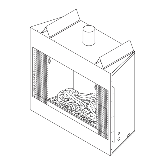
Page 13: Fireplace Setup
IREPLACE ETUP 1. Remove the box containing the log from the firebox and discard the two (2) shipping pads. Carefully remove the log from the box. 2. Position log over burner as shown in Figure 5. Wear protective gloves to place glowing ember meterial in front and on top of burner tube. - Page 14 PERATING NSTRUCTIONS Warning!: Never operate this unit with the glass removed. FOR YOUR SAFTEY READ BEFORE LIGHTING FOR YOUR SAFTEY READ BEFORE LIGHTING WARNING! WARNING! IF YOU DO NOT FOLLOW THESE INSTRUCTIONS EXACTLY, A FIRE OR IF YOU DO NOT FOLLOW THESE INSTRUCTIONS EXACTLY, A FIRE OR EXPLOSION MAY RESULT CAUSING PROPERTY DAMAGE, PERSONAL EXPLOSION MAY RESULT CAUSING PROPERTY DAMAGE, PERSONAL INJURY OR LOSE IF LIFE.
-
Page 15: Operating Instructions
PERATING NSTRUCTIONS LECTRONIC GNITION YSTEM STOP! Read the safety information at the beginning of this section. Turn off the electric power to the appliance. This appliance is equipped with an ignition device which automatically lights the pilot. Do NOT try to light the pilot by hand. - Page 16 AINTENANCE NSTRUCTIONS YELLOW TIPPED FLAMES YELLOW TIPPED FLAMES IGURE 1. LOOK DOWN BETWWEN THE LOGS TO SEE THE BURNER. 1. LOOK DOWN BETWWEN THE LOGS TO SEE THE BURNER. THE FLAMES SHOULD BE STABLE ON THE BURNER. THE FLAMES SHOULD BE STABLE ON THE BURNER. 2.
- Page 17 & R UTSIDE OMBUSTION RECAUTIONS ECOMMENDATIONS : The use of outside air for combustion is optional unless required by building codes. It is only necessary to supply outside combustion air to one side of the fireplace. Use the model OAC4 combustion air kit. 1.
-
Page 18: Combustion Air Assembly
OMBUSTION SSEMBLY OAC-4 C ODEL OMBUSTION SSEMBLY 1. Remove the cover plate from the 4-inch outlet opening location on the left outside of the fireplace. DO NOT remove the cover if the outside air will not be connected. 2. Place the starting collar (4 inch) into the hole on the left side of the fireplace. Fasten it in place with the four sheet metal screws provided. -
Page 19: Troubleshooting
ROUBLESHOOTING While the manufacturer has made every reasonable effort to insure that this heater operates properly and satisfactorily, sometimes problems do arise. The following troubleshooting chart lists several problems with their probable cause and solution. Any adjustments and/or replacements must be made by a qualified person. Do not replace any component with a different type. - Page 20 ARTS All repair part orders should be placed through your local dealer. To ensure prompt and accurate service, please provide the following information when placing a repair part order: Model number of your Appliance, Part Name, Part Number, and Quantity of parts needed. Technical Service Department 2813 W.
- Page 21 OTES 53D9015. Rev 1 03/03...
- Page 22 OTES 53D9015. Rev 1 03/03...
- Page 23 OTES 53D9015. Rev 1 03/03...
- Page 24 TTENTION PPLIANCE NSTALLER LEASE RETURN THESE PERATING NSTALLATION NSTRUCTIONS TO THE PPLIANCE FOR ONSUMER 53D9015. R 1 03/03...
Need help?
Do you have a question about the BBV400NV and is the answer not in the manual?
Questions and answers