
Subscribe to Our Youtube Channel
Related Manuals for GRASS VALLEY LDK 4489 Xpander


Summary of Contents for GRASS VALLEY LDK 4489 Xpander
- Page 1 User’s Guide 3922 496 30691 August 2009 v6.0 LDK 4488, LDK 4489 SuperXpander/Xpander...
-
Page 2: Declaration Of Conformity
Liable to technical alterations in the course of further development. Trademarks Grass Valley and Infinity are trademarks of Grass Valley, Inc. All other tradenames referenced are service marks, trademarks, or registered trademarks of their respective companies. -
Page 3: Table Of Contents
Table of contents Chapter 1 – Introduction System overview ........... . . 15 Versions . - Page 4 LDK 4489 Xpander ........
- Page 5 End-of-life product recycling Grass Valley’s innovation and excellence in product design also extends to the programs we’ve established to manage the recycling of our products. Grass Valley has developed a comprehensive end-of-life product take back program for recycle or disposal of end-of-life products.
-
Page 6: Important Information
50 kg; • Grass Valley clearly states that it is unacceptable with respect to safety to use Triax cables (for the interconnection between Base Station and the SuperXpander/Xpander) with knowingly a short circuit between the inner and outer shield. Also the use of coax cables or the use of patch panels with a short circuit between the inner and outer shield is prohibited;... - Page 7 • There are no user serviceable parts inside. Refer servicing to qualified personnel only or contact your local Grass Valley representative; • Observe local building safety, fire protection and electrical installation standards during installation and operation of this equipment; •...
- Page 8 Last von mehr als 50 kg trägen kann; • Grass Valley erklärt daß es im Zusammenhang mit der Sicherheit nicht gestattet ist Triaxkabel zu verwenden (für die Verbindung zwischen Base Station und SuperXpander/ Xpander) die wissentlich ein Kurzschluß zwischen der innere und aussere Abschirmung haben.
- Page 9 • Dieses Produkt enthält keine Anwenderteile. Reparatur und Wartung nur von qualifiziertem Fachpersonal vornehmen lassen oder nehmen Sie Kontakt auf mit Ihrem Grass Valley Vertretene; • Beim Einbau und Betrieb dieser Ausrüstung müssen die örtlichen Gebäudesicherheits- und Brandschutzvorschriften beachtet werden;...
-
Page 10: Tripod Installation
Installation notices For proper installation the following NEC articles should be noticed: – Installation of equipment (NEC article 800.18); – Avoid contact with conductors of other systems (NEC article 810.13); – Provide extensive, separate clearance requirements for indoor and outdoor locations (NEC article 810.18). - Page 11 Switzerland Supply cords of equipment having a rated current not exceeding 10 A shall be provided with a plug complying with SEV 1011 or IEC 884-1 and the following dimension sheet: – SEV 6534-2.1991 Plug type 12: L+N+PE250 V 10 A Apparatus which is fitted with a flexible cable or a cord and is designed to be connected to a mains socket conforming to BS 1363 by means of that flexible cable or cord and plug, shall be fitted with a “standard plug”...
- Page 12 This Class 1 Laser Product may only be used with other Class 1 classified products such as the Grass Valley HD Fiber Base Stations or LDK cameras equipped with HD Fiber adapters. LDK 4488, LDK 4489 SuperXpander/Xpander User’s Guide (v6.0)
- Page 13 Cleaning fiber-optic connectors WARNING Always switch off power before cleaning the connectors. WARNING Never clean an optical connector attached to a fiber that is carrying light. Particles of foreign matter on the tip of a ferrule can have a disabling effect on fiber-optic transmission.
- Page 14 LDK 4488, LDK 4489 SuperXpander/Xpander User’s Guide (v6.0)
-
Page 15: Chapter 1 - Introduction
The Grass Valley SuperXpander/Xpander is such a solution. Compatible with most LDK camera* families, it supports box-type lenses, teleprompters and high-resolution viewfinders. -
Page 16: Versions
Chapter 1 - Introduction 1.2 Versions Four versions of the SuperXpander/Xpander are available: LDK 4489 Xpander • The LDK 4489/10 Xpander supports box-type lenses and features mounting capability for Grass Valley 7-inch viewfinders. • The LDK 4489/00 Xpander is equipped with additional CVBS and component (YPrPb) viewfinder outputs. -
Page 17: Chapter 2 - Installation
LDK 8000 Elite HD camera no minimum status (all software versions are compatible) ☞ Note If your camera software version needs to be updated to meet the requirements, please contact your local Grass Valley representative. LDK 4488, LDK 4489 SuperXpander/Xpander User’s Guide (v6.0) -
Page 18: Installing The Viewfinder Support
Chapter 2 - Installation 2.2 Installing the viewfinder support To mount a 7-inch viewfinder on top of the SuperXpander/Xpander you need to install the viewfinder support that was supplied with the viewfinder. viewfinder support support (right side) Torx screws viewfinder socket Mounting procedure Remove the camera if it is already mounted. -
Page 19: Exchanging The Transmission Module
Chapter 2 - Installation 2.3 Exchanging the transmission module The SuperXpander/Xpander is supplied with either a Triax or a Fiber transmission module, depending on the base station and camera connector type you are using. You can exchange the transmission module easily to use the SuperXpander/Xpander with a different transmission system or connector type. - Page 20 Chapter 2 - Installation LDK 4488, LDK 4489 SuperXpander/Xpander User’s Guide (v6.0)
-
Page 21: Chapter 3 - Assembly
Chapter 3 - Assembly Chapter 3 Assembly 3.1 Assembly order 7-inch viewfinder camera body attachment plate for pan bars studio (option for lens LDK 4488/10 and LDK 4489/10) balance knob tripod head It is important that you assemble and disassemble the units in the right order. The correct order of assembly is as follows: Attach the SuperXpander/Xpander to the tripod. -
Page 22: Tripod Mounting
Chapter 3 - Assembly 3.2 Tripod mounting Caution Only mount the unit on a tripod or pedestal and head that can carry a load of more than 50 kg (110 lbs). To mount the SuperXpander/Xpander on a tripod, first attach the tripod wedge plate to the underside of the SuperXpander/Xpander as follows: Lay the SuperXpander/Xpander on its side. -
Page 23: Mounting A Camera
Chapter 3 - Assembly Swing the lens downwards so that the lower lens pin fits into the hole in the front of the SuperXpander/Xpander. Turn the lens locking handle clockwise to secure the lens in place. If a zoom control is used, attach the zoom control cable to the lens. 3.4 Mounting a camera To mount the camera into the SuperXpander/Xpander follow these instructions: Make sure that the SuperXpander/Xpander is mounted firmly on the tripod. - Page 24 Chapter 3 - Assembly Hold the camera at a slight angle and place the front onto the Quick Mount plate behind the rear stud. Level the camera and slide it forward slightly to rest on the Quick Mount plate. CAUTION: To prevent damaging the zoom control make sure it does not hit the bracket while inserting the camera into the...
- Page 25 Chapter 3 - Assembly Push the camera all the way forward along the wedge-shaped groove until the rear stud engages the rear of the camera. When he camera is correctly locked into position lever A springs out. wedge-shaped groove Quick Mount plate rear stud Adjust the position of the camera with levers C and D so that the bayonet ring engages the lens.
-
Page 26: Transport Position
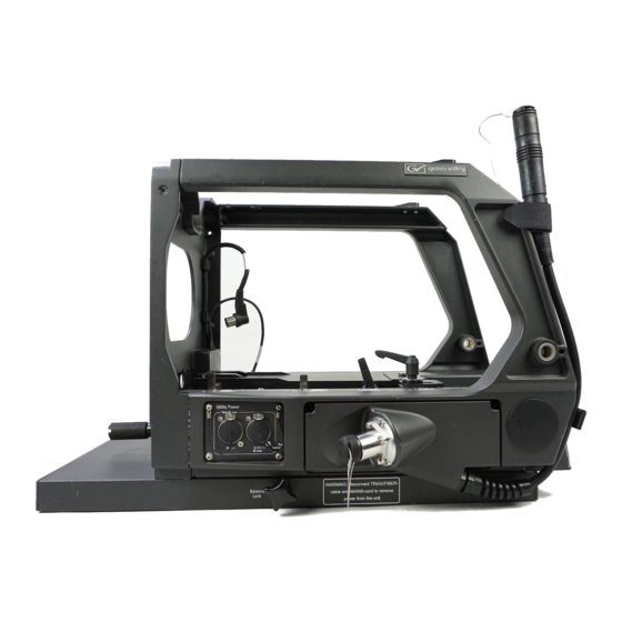
Chapter 3 - Assembly 3.5 Transport position The SuperXpander/Xpander can be transported in a safe way without the need to remove the camera and the viewfinder. To bring the unit into transport position proceed as follows: Remove the mains power lead (if used) and the Triax or fiber cable from the SuperXpander/Xpander. -
Page 27: Cable Clamp
Chapter 3 - Assembly 3.7 Cable clamp When the lens and camera are mounted on the SuperXpander/Xpander it is necessary to clamp the camera Triax or fiber cable. Proceed as follows: Loosen the cable clamp on the right side of the footbed by turning it counterclockwise. Put the cable into the clamp. - Page 28 Chapter 3 - Assembly LDK 4488, LDK 4489 SuperXpander/Xpander User’s Guide (v6.0)
-
Page 29: Chapter 4 - Control Panel
Chapter 4 - Control panel Chapter 4 Control panel 4.1 Buttons The LDK 4488 SuperXpander is equipped with a control panel at the rear of the unit. This panel includes an LCD screen and buttons for controlling the camera and the viewfinder. The buttons on the control panel have colored backlighting that indicates the state of the button. -
Page 30: Lcd Display
Chapter 4 - Control panel 4.2.2 LCD display The LCD display shows menus, functions and values. When no menu is selected the display shows a status screen that includes the transmission mode and power status. LDK 4488 SuperXpander Transmiss: Triax Local Pwr: Yes Util Pwr: Disabled... -
Page 31: Menu Function Lists
Chapter 4 - Control panel 4.2.7 Menu function lists The following tables provide an overview of functions included in the SuperXpander control panel. Note that the availability of some functions depends on your camera configuration. Menu 1 Switch Function Function Function <... - Page 32 Chapter 4 - Control panel Menu 2 Switch Function Function Function < page 1 > top-left ND Filter Control of the ND Filter in the camera. If the filter is not motorized this is an indication. top-right FX Filter Control of the FX filter in the camera, if available. bottom-left AutoWhite Off,Window,...
-
Page 33: Operational Panel Controls
Chapter 4 - Control panel 4.3 Operational panel controls 4.3.1 Panel view right on air/iso power remote indicators indicator indicator ON AIR POWER REMOTE MENU MENU MENU MENU ON AIR INDI- Y/-Y Y/EXT PROG CATOR ZOOM MARKER TEXT R/-R EXT 1 CENTER SELECT G/-G... -
Page 34: Viewfinder Control Buttons
Chapter 4 - Control panel 4.3.4 Viewfinder control buttons This group of buttons controls what is displayed in the viewfinder: Button: Function ON AIR DIM Switches the brightness of the On Air lamp on the viewfinder up and down in steps. INDICATOR Turns all indicators on the viewfinder screen On or Off MARKER... -
Page 35: Chapter 5 - Power
Chapter 5 - Power Chapter 5 Power 5.1 Switching on power Use the On/Off switch on the right side panel to switch the SuperXpander/Xpander and camera on and off. The power indicator lights when the system is switched on. On/Off Power switch indicator... -
Page 36: Fiber Cable Lengths
Chapter 5 - Power The following table gives an approximation of the maximum Triax cable length versus utility power consumption (the nominal SuperXpander/Xpander system power consumption is already taken into account for these values). Utility power Triax cable Triax cable... -
Page 37: Utility Power
120 W. If the variable output is not used, the fixed output can deliver max. 120 W. 5.4.2 LDK 4489 Xpander When the LDK 4486 Utility power unit is installed (default) one power output is available. The socket on the left provides a fixed voltage of 15 V . -
Page 38: Power Indication
Chapter 5 - Power 5.4.3 Power indication The utility power indicator provides information about the power output(s): Indicator Description Yellow Normal operation. Power is available. Power overload on the variable power output (applies to the SuperXpander only) Off (in remote mode) In remote mode this indicates that there is a power overload on the fixed power output. -
Page 39: Left Side Panel
Chapter 6 - Connectors Chapter 6 Connectors 6.1 Left side panel lens interface connector Triax or fiber connection to camera Triax connection to Base Station 15V = 5-12V = DC OUT Utility power Utility power output (fixed) output (variable) 6.1.1 Utility power output (fixed) Description no connection no connection... -
Page 40: Utility Power Output (Variable)
Chapter 6 - Connectors 6.1.2 Utility power output (variable) Note: This output is only avaible on the LDK 4488 SuperXpander. *) variable voltage level can be set using Description the SuperXpander operation panel. no connection no connection 0 to 12 V XLR 4-pin male 6.1.3 Lens interface connector ... -
Page 41: Right Side Panel
Chapter 6 - Connectors 6.2 Right side panel Triax or fiber connection to camera Viewfinder BNC Viewfinder Power Script Active Light 100 - 240V~ 50-60Hz 3A VF C onn. T4AH 250V Local 12V - 6VA Power mains script component CVBS viewfinder power light... -
Page 42: Viewfinder Component Outputs (3X)
Chapter 6 - Connectors 6.2.3 Viewfinder component outputs (3x) Note: these outputs are only available on the LDK 4488/00 and LDK 4489/00. These 3 BNC sockets provide video output (component video) of the viewfinder signal. BNC connector (3x) Y (1.0 Vpp with sync), Pr (0.7 Vpp), Pb (0.7 Vpp); 6.2.4 External CVBS output Note: this output is only available on the LDK 4488/00 and LDK 4489/00. -
Page 43: Specifications For Ldk 4488, Ldk 4489
Chapter 7 - Specifications Chapter 7 Specifications 7.1 Specifications for LDK 4488, LDK 4489 Item Value Power Power requirements 100 to 240 V ; 50 to 60 Hz 3 A; fuses (2x): T4.0 AH 250 V Power consumption 250 VA max. fully equipped Power connection IEC type 3-pin male Environment... -
Page 44: Dimensions
Chapter 7 - Specifications 7.2 Dimensions Figure 7-1. Dimensions of the LDK 4488, LDK 4489 (with Triax transmission unit) 125.5 LDK 4488, LDK 4489 SuperXpander/Xpander User’s Guide (v6.0)
Need help?
Do you have a question about the LDK 4489 Xpander and is the answer not in the manual?
Questions and answers