
Related Manuals for GRASS VALLEY EYECATCHER EC270


Summary of Contents for GRASS VALLEY EYECATCHER EC270
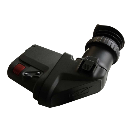
- Page 1 EYECATCHER EC270 2.7-Inch Color LCD Ocular Viewfi nder Service Manual 3922 496 32011 Version V1.0 www.grassvalley.com May 2013...
-
Page 2: Fcc Class A Statement
All other tradenames referenced are service marks, trade marks, or registered trademarks of their respective compa- nies. Website Visit the Grass Valley public website to download the latest user’s guide updates and additional information about your broadcast product: www.grassvalley.com Eyecatcher 2.7” LCD VF Service Manual V1.0... - Page 3 DOCUMENT INDENTIFIER EYECATCHER_LCD_VF_Servicemanual DATE 01-May-2013 KEYWORDS Service Manual Documentation EC270 COMPANY Grass Valley Nederland B.V. DOCUMENT HISTORY Release Date Reason of change Status Distribution November 2012 Initial Version Initial Internal May 2013 Published version Released Worldwide Eyecatcher 2.7” LCD VF Service Manual V1.0...
-
Page 4: Table Of Contents
Table of contents Chapter 1 Front page ............1-1 Decleration of Conformity . - Page 5 Chapter 4 Service Spare Parts Eyecatcher Main Parts ..........4-1 Top Housing Assy.
-
Page 6: End Of Life Product Recycling
Grass Valley’s end-of-life product take back program assures proper disposal by use of Best Available Technology. This program accepts any Grass Valley branded equipment. Upon request, a Certifi cate of Recycling or a Certifi cate of Destruction, depending on the ultimate disposition of the product, can be sent to the requester. -
Page 7: Safety Summary
Safety Summary This information is intended as a guide for trained and qualifi ed personnel who are aware of the dangers involved in handling potentially hazardous electrical / electronic equipment. It is not intended to contain a complete list of all safety precautions which should be observed by personnel in using this or other electronic equipment. -
Page 8: Special Tools
Special tools Extraction Tool Part number 1688076 Supplier: Farnell To disconnect the connector, insert the end portion of the tool under the connector fl anges an pull off vertically, in the direction of the connector mating axis. To mate the connector, the mating axes of both connectors must be aligned and the connectors can be mated. - Page 9 Aardvark Tool Supplier: www.totalphase.com/products/aardvark_i2cspi Download Tool Flat Panel Viewfi nder 3922 407 58341 Download Tool FP VF Eyecatcher 2.7” LCD VF Service Manual V1.0 1-10...
-
Page 10: Chapter 2 Exploded Views
Chapter 2 Exploded Views: 2.1 Front View Microphone Clamp Eyepiece Tally Back Menu/Peak Contrast Brightness Switches: -----Rotary Knobs----- Rotary Knob Mode Flying Lead Switch Knob Tally SW C (Assignable) Eyecatcher 2.7” LCD VF Service Manual V1.0... -
Page 11: Rear View
Rear View Switch A-B Eyepiece (Assignable) Release Knob Tally Light Eyepiece Release Knob Eyecatcher 2.7” LCD VF Service Manual V1.0... -
Page 12: Dismanteling Flowchart
Chapter 3 Replacement Section: 3.1 How to use: The replacement section consists of: Dismantling Flowchart . On this fl owchart, locate the part that has to be replaced. Disassemble the unit part by part till you reach the part to be replaced. After replacement, assemble the unit in reverse order. -
Page 13: Microphone Clamp Assy
3.2 Flowchart EYECATCHER EC270 2.7” LCD Viewfinder Eyecatcher Bottom Housing Assy Top Housing Assy Mechanics LCD Housing Assy Bottom Housing Assy Top Housing Assy Main Board 2.7” VF User IO Board 2.7” VF 3922 406 56371 3922 406 56381 Tally Cover Assy Flying Lead Cable Assy 3922 407 62721 3922 407 62701... - Page 14 3.3 Replacements Removal of the Microphone Clamp Assy ->Turn the Thumb Screw counter clockwise, to release the Microphone Assy Eyecatcher 2.7” LCD VF Service Manual V1.0...
-
Page 15: Viewfi Nder Housing
How to open the Viewfi nder Housing First remove: Page 3-3 Microphone Holder ->Unscrew the fi ve screws on the bottom side. ->Place the Viewfi nder with the Top Housing down. ->Open the housing, be carefull for the internal wiring. Eyecatcher 2.7”... -
Page 16: Bottom Housing Assy
Bottom Housing Assy First remove: Page 3-3 Microphone Holder Page 3-4 Open the Viewfi nder Housing ->Disconnect the fl atcable from the LCD Housing assy to X6119. ->Disconnect the Power/Control part of the Flying Lead to X7. ->Disconnect the Y, R-Y and B-Y coax connectors to X1, X2 and X3 ->Use the special Extraction Tool to pull off the connectors. -
Page 17: Flying Lead Cable Assy
Flying Lead Cable Assy First remove: Page 3-3 Microphone Holder Page 3-4 Open the Viewfi nder Housing Page 3-5 Bottom Housing Assy ->Unscrew two screws to release the Grounding Clamp. ->Remove the Flying Lead Cable Eyecatcher 2.7” LCD VF Service Manual V1.0... -
Page 18: User Io Board 2.7" Vf
User IO Board 2.7 Inch VF First remove: Page 3-3 Microphone Holder Page 3-4 Open the Viewfi nder Housing Page 3-5 Bottom Housing Assy Page 3-6 Flying Lead Cable Assy ->Remove the three Knobs for Peaking, Contrast and Brightness ->Disconnect the fl atcable to the ID board on X420 ->Unscrew the two screws which hold the IO board. - Page 19 Main Board 2.7 inch VF (in Top Housing) First remove: Page 3-3 Microphone Holder Page 3-4 Open the Viewfi nder Housing Page 3-5 Bottom Housing Assy ->Unscrew three screws to remove the Main Board. ->Remove the Main Board. Eyecatcher 2.7” LCD VF Service Manual V1.0...
-
Page 20: Main Board 2.7"Vf
Tally Cover Assy (in Top Housing) First remove: Page 3-3 Microphone Holder Page 3-4 Open the Viewfi nder Housing Page 3-5 Bottom Housing Assy Page 3-8 Main Board ->Unscrew the screw to remove the Tally Cover Assy. Eyecatcher 2.7” LCD VF Service Manual V1.0... - Page 21 2.7 Inch VF LCD Housing Assy First remove: Page 3-3 Microphone Holder Page 3-4 Open the Viewfi nder Housing 1 -> Disconnect the fl atcable from the LCD Housing assy to X6119. 2 -> Unscrew the three screws to release the 2.7” VF LCD Housing Assy. 3-10 Eyecatcher 2.7”...
-
Page 22: Vf Lcd Housing Assy
VF LCD Housing Flatcable First remove: Page 3-3 Microphone Holder Page 3-4 Open the Viewfi nder Housing Page 3-10 2.7” VF LCD Housing Assy 1 -> Unscrew the four screws to release the LCD Display from the LCD Housing. 2 -> Disconnect the fl... -
Page 23: Mirror Housing
Mirror Housing First remove: Page 3-3 Microphone Holder Page 3-4 Open the Viewfi nder Housing Page 3-10 2.7” VF LCD Housing Assy 1 -> Press the two Clamps to release the Eyepiece Assy Mirror House Eyepiece Assy 3-12 Eyecatcher 2.7” LCD VF Service Manual V1.0... -
Page 24: Eyecatcher Main Parts
Chapter 4 Spare parts: 4.1 Eyecatcher Main Parts 8926 530 32001 Eyecatcher Top Housing Assy Bottom Housing Assy 2.7” VF LCD Housing Assy Eyecatcher 2.7” LCD VF Service Manual V1.0... - Page 25 Mirror House 2.7” VF Assy 2.7” VF Eyepiece Assy Microphone Clamp Assy 2.7” VF Assy Eyecatcher 2.7” LCD VF Service Manual V1.0...
-
Page 26: Top Housing Assy
4.2 Top Housing Assy Top Housing Assy 3922 406 56371 Main Board 2.7” VF 3922 407 62721 Tally Cover Assy Eyecatcher 2.7” LCD VF Service Manual V1.0... -
Page 27: Bottom Housing Assy
4.3 Bottom Housing Assy Bottom Housing Assy 3922 406 56381 User IO Board 2.7” VF 3922 407 62701 Flying Lead Cable Assy 2.7” 3922 205 00005 FFC 10P 50mm 3922 411 56811 PCB F FPC 45P 110mm 3922 400 11641 Volume Knob Eyecatcher 2.7”... -
Page 28: Vf Lcd Housing Assy
4.4 2.7” VF LCD Housing Assy 3922 407 62231 2.7” VF LCD Housing Assy 3922 407 63311 PCB F FPC 45P 160mm Folded Eyecatcher 2.7” LCD VF Service Manual V1.0... -
Page 29: Mirror House 2.7" Vf
4.5 Mirror House 2.7” VF 3922 407 62271 Mirrror House 2.7” VF Eyecatcher 2.7” LCD VF Service Manual V1.0... -
Page 30: Vf Eyepiece Assy
4.6 2.7” VF Eyepiece Assy 3922 407 62291 2.7” VF Eyepiece Assy 3922 083 03141 Rubber Cap Eyecatcher 2.7” LCD VF Service Manual V1.0... -
Page 31: Microphone Clamp Assy 2.7" Vf
4.7 Microphone Clamp Assy 2.7” VF 3922 407 62711 Microphone Clamp Assy 2.7” VF 2622 080 89021 O-Ring Compound Vit Eyecatcher 2.7” LCD VF Service Manual V1.0... -
Page 32: Chapter 5 Blockdiagrams
Chapter 5 Blockdiagrams 5.1 Power 3922 406 56371 Main Board LCD Board 2,7 Inch VF 3922 406 56381 User IO Board ID Board Viewfinder Connector Signal Pin(s) 12v_Cam 9,10 +Batt_Prot DC-DC -2,5V Converter HOTSWAP X6119 PROTECTION +3,3V DC-DC Converter DC-DC +2,5V Converter +7V5... -
Page 33: Video
5.2 Video 3922 406 56371 Main Board LCD Board 2,7 Inch VF 3922 406 56381 User IO Board ID Board Viewfinder Connector X6119 LVDS (0:3) FPGA LVDS (0:3) Parallel (0:7) Signal X6119 N(0) P(0) (0:7) N(1) P(1) Converter N(2) (0:9) (0:7) P(2) N(3) -
Page 34: Control And Diagnostics
5.3 Control and Diagnostics 3922 406 56371 Main Board LCD Board 2,7 Inch VF 3922 406 56381 User IO Board ID Board Signal Pin(s) Viewfinder Connector 1,2,4 BUS CAM BUS I²C CAM X6100 BUFFER Test Connector I²C X6119 SPI-Bus SPI-Bus FPGA Led-Brightness Led-Brightness... -
Page 35: Chapter 6 Diagnostics
Chapter 6 Diagnostics: 6.1 Led indicators MP39 R418 R420 R419 LIGHT DIRECTION LIGHT DIRECTION LIGHT DIRECTION BD22 R422 C438 R421 R442 R448 C439 C384 R441 R447 R403 R400 R563 R564 D224 C159 TS11 C442 C386 R592 R325 C437 C324 C316 R145 TS23 TS22... - Page 36 R438 R661 R437 R424 R436 R660 R434 R435 R662 R433 R659 MP37 C160 R415 R610 C140 C317 C314 R405 D223 C318 D223 C152 C153 C139 R646 R613 R306 C356 R500 R501 C286 R582 R581 C135 C329 C344 C352 R622 C398 C357 C348 S6500...
-
Page 37: Status Information
6.2 Status Information Diagnostic Status Info Menu will show in an overview information about the Viewfi nder, this information can also be exported to an Excel sheet with the Script fi le “CollectVFStatusInfo_LDK5303.tsc”. Information available: • LCD Viewfi nder type number •... - Page 38 Status Information exporting to an Excel sheet: Connect the LCD Viewfi nder with a null-modem cable to a PC or Laptop, with LDK Scripter version 8.0 or later on it. Select RS232 as Down load Method. (It is also possible to use the download tool. Select USB- aardvark-iic as Download Method, see Chaper 7, Maintenance) Run the “CollectVFStatusInfo_LDK5303.tsc”...
- Page 39 Eyecatcher 2.7” LCD VF Service Manual V1.0...
-
Page 40: Operation Log Data
6.3 Operation Log Data Operation Log Data function will show in an overview information about the usage of the LCD Viewfi nder: • Total run-hours • Power cycles • Calibration Count • Run Hours Log Data • Temperature Log Data •... - Page 41 Operation Log Data exporting to an Excel sheet: It is also possible to export this information to an Excel Sheet with script “CollectVFOperation LogData_LDK5303.tsc”. Make sure that the fi le ‘OperLog_template.xls” is also in the same Directory. Connect the Viewfi nder with a null-modem cable to a PC or laptop with LDK Scripter version 7.0 or later installed on it.
-
Page 42: Chapter 7 Maintenance
Chapter 7 Maintenance 7.1 Package Download It is possible to update the Eyecatcher EC270 VF in the stand-alone mode when you have: • Aardvark I²C/SPI Host Adapter. • Power Supply (12 Vdc). • Laptop or PC with LDKScripter 7.3 or higher. - Page 43 TOTALPHASE Website: www.totalphase.com Install the drivers for the Aardvark by running the fi le “TotalPhaseUSB-v2.11”. Connect the Aardvark via the USB connection to your PC or Laptop for Firmware update. Update by clicking the fi le “aafl ash-windows’. Eyecatcher 2.7” LCD VF Service Manual V1.0...
- Page 44 The next DOS-screen will pop-up. Fill in for Port: “0” and “enter” Firmware update is completed. The Aardvark is ready for use. Eyecatcher 2.7” LCD VF Service Manual V1.0...
- Page 45 Connection Diagram 10.7 to 17 Vdc in Download tool LDK 5307 When the Download tool is connected correctly it is possible to update the Eyecatcher EC270 VF stand-alone. Warning: Do not switch off power during download process. Warning: Do not switch off power during download process.
- Page 46 Run “load_package_392240761791.tsc” from the Package Eyecatcher directory. Follow the instructions on the screen. Next Pop-up screen will appear. Depending on the Status of the Viewfi nder, downloading can start. Also the “CollectVFStatusInfo_LDK5303.tsc” can collect data for the Excel sheet. The “CollectVFOperationLogData_LDK5303” will work in this Stand Alone Mode.
Need help?
Do you have a question about the EYECATCHER EC270 and is the answer not in the manual?
Questions and answers