
Related Manuals for Cisco ISB7000 Series


Summary of Contents for Cisco ISB7000 Series
- Page 1 Installation Manual Cisco ISB7000 Series High-Defi nition IP Set-Tops Energy Star V3...
-
Page 3: Table Of Contents
Contents Notice for Installers ......................4 IMPORTANT SAFETY INSTRUCTIONS................4 Change the Way You Watch TV ..................6 Identify Your Set-Top ....................... 6 Safety First ........................7 Serial Number ........................7 In This Manual ........................7 Open Source GNU GPL Statement .................. 7 Front Panel ........................ -
Page 4: Notice For Installers
Notice for Installers The servicing instructions in this notice are for use by qualifi ed service personnel only. To reduce the risk of electric shock, do not perform any servicing other than that contained in the operating instructions, unless you are qualifi ed to do so. Note to System Installer For this apparatus, the cable shield/screen shall be grounded as close as practical to the point of entry of the cable into the building. - Page 5 IMPORTANT SAFETY INSTRUCTIONS, continued Handling Disposable Batteries Protect from Exposure to Moisture This product may contain disposable batteries. Heed the following and Foreign Objects warning and follow the Battery Safety and Battery Disposal instructions below. WARNING: Avoid electric shock and fi re hazard! Do not expose this product to dripping or splashing liquids, WARNING: There is danger of explosion if the battery rain, or moisture.
-
Page 6: Change The Way You Watch Tv
Change the Way You Watch TV ® Welcome to Internet Protocol Television (IPTV). The Cisco ISB7000 Series High-Defi nition IP Set-Tops bring a rich, new set of interactive services directly to you through your TV and your in-home IP network. -
Page 7: Safety First
Cisco Systems, Inc. Open Source GNU GPL Statement Cisco ISB7000 set-tops contain(s), in part, certain free/open source software (“Free Software”) under licenses which generally make the source code available for free copy, modifi cation, and redistribution. Examples of such licenses include all the licenses sponsored by the Free Software Foundation (e.g. GNU General Public License (GPL), GNU Lesser General Public License (LGPL), Berkeley Software Distribution (BSD), the MIT licenses and diff erent versions of the Mozilla and Apache licenses). -
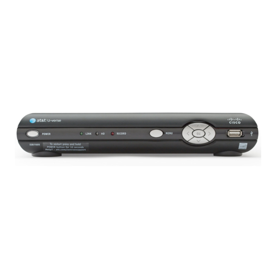
Page 8: Front Panel
Front Panel ISB7030 T14255 1 Power Turns the set-top on or places it in standby. To restart the set-top, press and hold the POWER button for 10 seconds. The LED is green 2 Model Number Identifi es the model number of your set-top as ISB7000, ISB7005, ISB7030, ISB7031, ISB7050, ISB7080, ISB7100, or ISB7150 3 Link Indicates network link status. -
Page 9: Back Panel
Back Panel TO WALL TO TV (VIDEO IN) (VIDEO OUT) VIDEO AUDIO NETWORK eSATA S-VIDEO OPTICAL POWER T14256 1 To Wall (Video In) Connect the set-top to in-house coaxial wiring, if applicable. (optional) 2 To TV (Video Out) Connect to TV. You must set the channel on your TV to the channel designated by your service provider (usually channel 3). -
Page 10: Connecting The Set-Top
Connecting the Set-Top To connect your set-top to your network and home entertainment devices, complete these steps. Because the connections for a high-defi nition (HD) or standard-defi nition (SD) TV are diff erent, you must determine if your TV is HD or SD. -
Page 11: Isb7005 Wireless Network Connection
ISB7005 Wireless Network Connection PO WER LINK The ISB7005 set-top allows for easy and secure setup of a wireless home network. The signal strength indicator on 7005 the front panel of the set-top indicates the strength of the wireless connection. Signal Strength Indicator The set-top must be paired with the wireless access T14822... -
Page 12: Connection For Isb7005 Wireless Set-Top
Connection for ISB7005 Wireless Set-Top The ISB7005 set-top allows for easy and secure establishment of a wireless home network. The signal strength indicator on the front panel of the set-top allows you to identify the strength of your wireless connection. ISB7005 PO WER LINK... -
Page 13: Connecting The Wireless Access Point To The Wireless Gateway
Connecting the Wireless Access Point to the Wireless Gateway RJ-45 Wireless 1. Connect the 12 VDC Power Supply Cable Gateway plug on the access point to the wall Ethernet Port power outlet. Use only the power adapter provided with the product. Reset 2. -
Page 14: Connecting To The In-Home Network
Connecting to the In-Home Network The following diagrams illustrate examples of the connections you can use to connect your set- top to your in-home network. Contact your service provider for the recommended connection method for your home. (This section does not apply to the ISB7005; see Connection for ISB7005 Wireless Set-Top on page 12.) Notes: •... -
Page 15: Connections For A High-Defi Nition Tv (Hdtv)
Connections for a High-Defi nition TV (HDTV) To use the set-top with an HDTV, you must make one of the following connections to view the HD content. Refer to the owner’s manual for your TV and the cabling diagrams in this manual for more detailed connection information. -
Page 16: Connections For A Standard-Defi Nition Tv (Sdtv)
Connections for a Standard-Defi nition TV (SDTV) When using the set-top with an SDTV, you must make one of the following connections to view content. Some SDTVs may not have all these connections. Refer to the owner’s manual for your TV and the cabling diagrams in this manual for more detailed information. -
Page 17: Connections For A Vcr Or Dvd Recorder
Connections for a VCR or DVD Recorder When using the set-top with a VCR or DVD recorder, you must make one of the following connections to view content. Although all connections provide you with quality service, we list the connections in our recommended order. -
Page 18: Connecting To An Hdtv With An Hdmi Connector
Connecting to an HDTV with an HDMI Connector Cable Used in this Confi guration • 1 HDMI Cable Notes: • The HDMI port on the TV must support high-bandwidth digital content protection (HDCP). • The HDMI interface supports Dolby ™ Digital 5.1 audio. -
Page 19: Connecting To An Hdtv With A Dvi Connector
Connecting to an HDTV with a DVI Connector Cables Used in this Confi guration • 1 HDMI-to-DVI Cable or 1 HDMI Cable and 1 HDMI-to-DVI Adapter • 1 Audio Left/Right Cable (You can also use an optical cable [indicated by the dotted line] instead of the Audio Left/Right Cable as shown in the diagram, dependent upon your TV’s capabilities.) Notes: •... -
Page 20: Connecting To An Hdtv With Component (Ypbpr) Connectors
Connecting to an HDTV with Component (YPbPr) Connectors Cables Used in this Confi guration • 1 Component Video Cable (YPbPr) • 1 Audio Left/Right Cable (You can also use an optical cable [indicated by the dotted line] instead of the Audio Left/Right Cable as shown in the diagram, dependent upon your TV’s capabilities.) WARNING: Electric shock hazard! Unplug all electronic devices before connecting or disconnecting any device cables to the set-top. -
Page 21: Connecting To An Sdtv With Component (Ypbpr) Connectors
Connecting to an SDTV with Component (YPbPr) Connectors Cables Used in this Confi guration • 1 Component Video Cable (YPbPr) • 1 Audio Left/Right Cable Note: The set-top must be set to the proper standard-defi nition mode. WARNING: Electric shock hazard! Unplug all electronic devices before connecting or disconnecting any device cables to the set-top. -
Page 22: Connecting To An Sdtv With An S-Video Connector
Connecting to an SDTV with an S-Video Connector Cables Used in this Confi guration • 1 S-Video Cable • 1 Audio Left/Right Cable WARNING: Electric shock hazard! Unplug all electronic devices before connecting or disconnecting any device cables to the set-top. Set-Top TO WALL TO TV... -
Page 23: Connecting To An Sdtv With An Rca-Type Connector
Connecting to an SDTV with an RCA-Type Connector Cables Used in this Confi guration • 1 RCA-type Video Cable • 1 Audio Left/Right Cable WARNING: Electric shock hazard! Unplug all electronic devices before connecting or disconnecting any device cables to the set-top. Set-Top TO WALL TO TV... -
Page 24: Connecting To An Sdtv With A Coaxial Cable
Connecting to an SDTV with a Coaxial Cable Cable Used in this Confi guration • 1 Coaxial Cable Note: You must set the channel on your TV to the channel designated by your service provider (usually channel 3). Contact your service provider for the channel information. WARNING: Electric shock hazard! Unplug all electronic devices before connecting or disconnecting any device cables to the set-top. -
Page 25: Connecting To A Home Theater System With Component (Ypbpr) Connectors
Connecting to a Home Theater System with Component (YPbPr) Connectors Cables Used in this Confi guration • 1 Component Video Cable (YPbPr) • 1 Audio Left/Right Cable (You can also use an optical cable [indicated by the dotted line] instead of the Audio Left/Right Cable as shown in the diagram.) Notes: •... -
Page 26: Connecting To A Stereo Vcr Or Dvd Recorder (Optional)
Connecting to a Stereo VCR or DVD Recorder (optional) The diagram below shows how to connect a recording device to your set-top. Although it is possible to watch TV using a connection through your VCR or DVD recorder to the TV, this connection may not provide the best picture, and HDTV users are restricted to an SD format. -
Page 27: Troubleshooting
Troubleshooting If the set-top does not perform as expected, the following tips may help. If you need further assistance, contact your service provider. No Picture • Verify that the power to your TV is turned on. • If the set-top is plugged into a wall switch, verify that the switch is in the ON position. •... -
Page 28: Avoid Screen Burn-In
Avoid Screen Burn-In Images such as letterbox bars or side bars, bright closed-captioning backgrounds, station logos, or any other stationary images may cause the display in your HDTV to age unevenly; this is known as screen burn-in. Refer to the owner’s manual that came with your HDTV for more information. CAUTION: Avoid screen burn-in. -
Page 29: Frequently Asked Questions
Frequently Asked Questions What Is Digital Television? Digital television (DTV) is a huge leap forward in television technology compared to analog television that has been widely available since the 1940s. DTV is delivered and displayed using digital encoding, similar to the way a PC operates. By using digital technology, there is no variation in picture and sound quality from the origination point until it is displayed on your television. -
Page 30: Picture Formats
Picture Formats What Is the Diff erence Between a Standard-Screen and a Wide-Screen HDTV? The type of screen your HDTV has (wide-screen or standard-screen) determines how the set-top displays programs on the screen. The picture format for an HDTV is a combination of aspect ratio and screen resolution and is diff erent for standard-screen and wide-screen HDTVs. -
Page 31: Index
Index Connection Coaxial Network 14 AC Power input Consumer electronic devices Arrow keys Controls See Front panel Aspect ratio 29, 30 Audio Out 9, 15, 16, 17 DC Power output Diagrams. See Connecting the set-top Back panel to other devices Burn-in of screen Digital Video Recorder. - Page 32 Index, continued To Wall (Video In) connector 9, 10, 14 To TV (Video Out) connector 9, 16, 24 Keys. See Front panel Troubleshooting Network 9, 10, 14 digital, what is it formats 29, 30 Optical Audio Output 9, 15, 19, 20, 25 HDTV, what is it programming recording...
-
Page 33: Compliance Information
Consult the service provider or an experienced radio/television technician for help. Cisco has tested and confi rmed that the ISB7000 set-top models Any changes or modifi cations not expressly approved by Cisco meet the Qualifi cation Criteria specifi ed in the ENERGY STAR Systems, Inc., could void the user’s authority to operate the... - Page 34 This product conforms to the following European directives: Systems for use within the EU. The use of software or fi rmware not supported or provided by Cisco Systems may result in the equipment -1999/5/EC for ISB7005 set-tops no longer being compliant with the regulatory requirements.
- Page 36 Lawrenceville, GA 30042 www.cisco.com Cisco and the Cisco logo are trademarks or registered trademarks of Cisco and/or its affi liates in the U.S. and other countries. A listing of Cisco’s trademarks can be found at www.cisco.com/go/trademarks. Manufactured under license from Dolby Laboratories. Dolby and the double-D symbol are trademarks of Dolby Laboratories.
Need help?
Do you have a question about the ISB7000 Series and is the answer not in the manual?
Questions and answers