
Related Manuals for Cisco RNG150


Summary of Contents for Cisco RNG150
- Page 1 User Guide Cisco RNG150 Digital-Only High-Defi nition Interactive Set-Top with Multi-Stream CableCARD Interface RNG150 POWER DATA REMOTE USB 2.0...
- Page 2 Notice to Installers The servicing instructions in this notice are for use by qualifi ed service personnel only. To reduce the risk of electric shock, do not perform any servicing other than that contained in the operating instructions, unless you are qualifi ed to do so. Note to System Installer For this apparatus, the coaxial cable shield/screen shall be grounded as close as practical to the point of entry of the cable...
-
Page 3: Table Of Contents
Contents IMPORTANT SAFETY INSTRUCTIONS ..................iv Welcome ............................1 Safety First ........................... 1 Identify Your Set-Top ........................1 What’s in the Carton? ........................2 Additional Equipment You Might Need ..................2 Front Panel Features ........................3 Back Panel Connectors ........................ 4 Connecting the Set-Top ........................ -
Page 4: Important Safety Instructions
IMPORTANT SAFETY INSTRUCTIONS Power Source Warning 1) Read these instructions. 2) Keep these instructions. A label on this product indicates the correct power source for this product. Operate this product only from an electrical 3) Heed all warnings. outlet with the voltage and frequency indicated on the product label. - Page 5 IMPORTANT SAFETY INSTRUCTIONS, continued Protect from Exposure to Moisture and Foreign Objects WARNING: Avoid electric shock and fi re hazard! Do not locate an outside antenna system in the vicinity of overhead power lines or power circuits. Touching power lines or circuits might be fatal. WARNING: Avoid electric shock and fi...
-
Page 7: Welcome
(HD) capability and broadband digital video services. Follow the instructions in this guide to install the RNG150, to become familiar with the buttons on the front panel, and to access your cable services. Then, enjoy the features of the RNG150 and change the way you watch TV. -
Page 8: What's In The Carton
POWER DATA REMOTE USB 2.0 • RNG150 Set-top with M-Card • Power Cord • User Guide Additional Equipment You Might Need You might need some of the cables and adapters shown below for connecting the set-top to your home entertainment devices. -
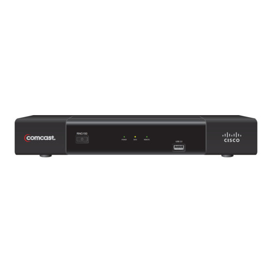
Page 9: Front Panel Features
Front Panel Features RNG150 POWER DATA REMOTE USB 2.0 T13672 1 Power Button Applies power to the set-top 2 Power LED Illuminates when the set-top is powered on. The LED is green 3 Data LED Illuminates when the set-top is receiving data. The LED is yellow 4 Remote LED Illuminates when the remote control is in use. -
Page 10: Back Panel Connectors
Back Panel Connectors M-CARD SN: PKCPTMFDV M-CARD MAC: 001BD746C7CB 14 15 T13673 1 Multi-Stream Installed by your service provider CableCARD 2 M-CARD Code Contains M-CARD serial number and MAC address Label 3 Bar Code Label Contains set-top serial number and MAC address 4 Cable In Connects to a coaxial cable that delivers the signal from your service provider 5 Video Out... -
Page 11: Connecting The Set-Top
Connecting the Set-top To connect your set-top to your entertainment devices, complete these steps. Determine if your TV is HD or SD and whether it is wide screen (16:9) or standard screen (4:3). See page 11 for more information. Make the connections for your TV and VCR as follows: •... -
Page 12: Connections For An Hdtv And Vcr
Connections for an HDTV and VCR To use the set-top with an HDTV, you must make one of the following connections to view the HD content. In addition, you can make connections to a digital or analog VCR to record to a VCR tape. Refer to your TV and VCR user guides and the cabling diagrams in this guide for more detailed connection information. -
Page 13: Connections For A Standard-Defi Nition Tv And Vcr
Connections for a Standard-Defi nition TV and VCR When using the set-top with an SDTV, you must make one of the following connections to view content. Some SDTVs may not have all these connections. In addition, you can make connections to a VCR to record to a VCR tape. Refer to your TV and VCR user guides and the cabling diagrams in this guide for more detailed information. -
Page 14: View Television Programming
View Television Programming Access Services and Programs Access cable services and programs by pressing the following keys on the remote control: • Guide–Access the on-screen guide. The on-screen guide displays schedules of TV programs and other services available from your cable service provider, such as video-on-demand and pay-per-view programs. •... -
Page 15: Troubleshooting
Troubleshooting If the set-top does not perform as expected, the following tips may help. If you need further assistance, contact your service provider. No Picture • Verify that the M-Card module is installed. • Verify that the power to your TV is turned on. •... -
Page 16: Frequently Asked Questions
Frequently Asked Questions What is Digital Television? Digital television (DTV) is a huge leap forward in television technology compared to analog television that has been widely available since the 1940s. DTV is delivered and displayed using digital encoding, similar to the way a PC operates. -
Page 17: Picture Formats
Picture Formats What is the Difference Between a Standard-Screen and a Wide-Screen HDTV The type of screen your HDTV has (wide screen or standard screen) determines how the set-top displays programs on the screen. The picture format for an HDTV is a combination of aspect ratio and screen resolution and is different for standard-screen and wide-screen HDTVs. -
Page 18: Connecting To An Hdtv With An Hdmi Connector
Connecting to an HDTV with an HDMI Connector WARNING: Electric shock hazard! Unplug all electronic devices before connecting or disconnecting any device cables to the set-top. Required cables: • 1 HDMI-to-HDMI cable RNG150 M-CARD SN: PKCPTMFDV M-CARD MAC: 001BD746C7CB Cable Input AUDIO HDMI CENTER... -
Page 19: Connecting To An Hdtv With A Dvi Connector
Electric shock hazard! Unplug all electronic devices before connecting or disconnecting any device cables to the set-top. Required cables: • 1 HDMI-to-DVI or 1 HDMI-to-HDMI cable and 1 DVI adapter • 1 audio Left/Right cable RNG150 M-CARD SN: PKCPTMFDV M-CARD MAC: 001BD746C7CB Cable Input AUDIO HDMI DVI/HDCP... -
Page 20: Connecting To An Hdtv With Component Input (Ypbpr)
Electric shock hazard! Unplug all electronic devices before connecting or disconnecting any device cables to the set-top. Required cables: • 1 set component video cables (YPbPr) • 1 audio Left/Right cable RNG150 M-CARD SN: PKCPTMFDV M-CARD MAC: 001BD746C7CB Cable Input AUDIO DVI/HDCP CENTER... -
Page 21: Connecting To A Home Theater System With Component Input (Ypbpr)
Required cables: • 3 sets component video cables (YPbPr) • 1 audio Left/Right cable • 2 coaxial digital audio cables RNG150 M-CARD SN: PKCPTMFDV M-CARD MAC: 001BD746C7CB Back of Home Cable Input Theater Receiver DIGITAL TV/CABLE... -
Page 22: Connecting To A Stereo Vcr And Hdtv (Optional)
Electric shock hazard! Unplug all electronic devices before connecting or disconnecting any device cables to the set-top. Required cables: • 1 RF coaxial cable • 2 sets composite A/V cables RNG150 M-CARD SN: PKCPTMFDV M-CARD MAC: 001BD746C7CB Cable Input RF IN Back of Stereo VCR... -
Page 23: Connecting To An Hdtv With A 1394 Connector
1 4-pin to 4-pin 1394 cable (Consult your TV user guide • 1 set audio Left/Right cable • 1 set composite A/V cables RNG150 M-CARD SN: PKCPTMFDV M-CARD MAC: 001BD746C7CB Cable Input 1394 IN Important: When you connect the set-top... -
Page 24: Index
Index 1394 4, 6, 17 Dashes display Diagrams. See Connecting the set-top to other devices Digital TV, What is it Outlet iv, 4 Display, LED Power input DVI connector 2, 4, 6, 13 Aspect ratio External hard disk drive. See SATA Back panel Burn-in of screen FAQs... - Page 25 Index, continued S-Video Keys. See Front panel; Back panel Safety ii, iv-v Scan rates Screen LED Display burn-in resolution size M-Card. See Multi-Stream CableCARD SD mode 4, 5, 7, 17 Multi-Stream CableCARD 2, 4, 10 SDTV Connections 7, 17 Picture What is it Doesn’t display Serial number, locating...
- Page 26 Index, continued Updating, software USB port VCR connection 6, 7, 16 View programs Watch TV 1, 8 Web access to product information Welcome Wide-screen TV YPbPr connector 4, 6, 7 HDTV connection 14 home theater connection SDTV connection Zoom picture 8, 11...
-
Page 27: Compliance Information
• Increase the separation between the equipment and and Scientifi c Atlanta are registered trademarks or trademarks receiver. of Cisco Systems, Inc. and/or its affi liates in the U.S. and certain • Connect the equipment into an outlet on a circuit different other countries. - Page 28 This document includes various trademarks of Cisco Systems, Inc. Please see the Trademarks section of this document for a list of the Cisco Systems, Inc., trademarks used in this document. All other trademarks mentioned in this document are the property of their respective owners.
Need help?
Do you have a question about the RNG150 and is the answer not in the manual?
Questions and answers