Table of Contents
Advertisement
Quick Links
Advertisement
Table of Contents

Related Manuals for Cisco ITV7900


Summary of Contents for Cisco ITV7900
- Page 1 User Guide Cisco ITV7900 Family IP Set-Tops ITV7900...
-
Page 3: Table Of Contents
Contents Notice for Installers ......................4 IMPORTANT SAFETY INSTRUCTIONS................4 Change the Way You Watch TV ..................6 What’s In the Carton? ...................... 6 Safety First ........................6 Identify Your Receiver with the Serial Number ..............6 In This Manual ........................6 Questions About Your Service. -
Page 4: Notice For Installers
Cisco and the Cisco logo are trademarks or registered trademarks of Cisco and/or its affi liates in the U.S. and other countries. To view a list of Cisco trademarks, go to this URL: www.cisco.com/go/trademarks. Third-party trademarks mentioned are the property of their respective owners. - Page 5 20110316_IP_No Tuner_Safety Informations relatives à la conformité Cisco et le logo Cisco sont des marques de commerce ou marques de commerce déposées de Cisco ou de ses fi liales aux Conformité aux normes de la FCC aux États-Unis États-Unis et dans d’autres pays. Pour voir la liste des marques de commerce de Cisco, visitez le site www.cisco.com/go/...
- Page 6 IMPORTANT SAFETY INSTRUCTIONS, continued Battery Disposal • The batteries may contain substances that could be harmful to Antenna Lead In Wire the environment. • Recycle or dispose of batteries in accordance with the battery manufacturer’s instructions and local/national disposal and recycling regulations. Ground Clamps Antenna Discharge Unit • The batteries may contain perchlorate, a known hazardous (NEC Section 810-21) substance, so special handling and disposal of this product might Grounding Conductors...
-
Page 7: Safety First
Welcome The Cisco® ITV7900 family of IP set-tops provide high-definition (HD) capability and broadband digital video services in exceptional picure and audio quality. On MoCA™- enabled set-tops, the MoCA connection enables an IP LAN connection over coaxial cable, which minimizes the need for new wiring in the home. On wireless-enabled set- tops, the connection with a video-centric access point/gateway, allows you to add new Wireless Protected Setup (WPS) -compliant clients to your home network giving you the flexibility to watch TV anywhere in the house. -
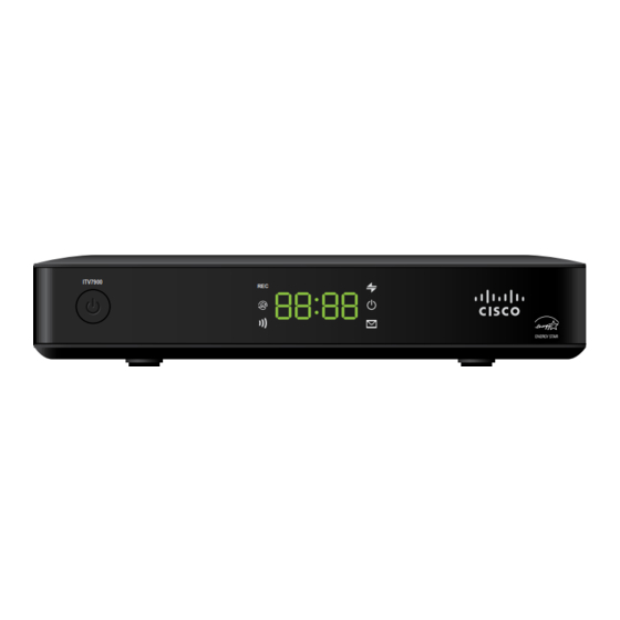
Page 8: Front Panel
Front Panel ITV7900 Power Turns the set-top on or places it in standby mode Display Displays the selected channel number and time of day. The display shows the following: • Record ( ) - Indicates a recording is in progress when illuminated •... -
Page 9: Back Panel
Back Panel IR REMOTE INPUT CABLE IN CABLE OUT VIDEO OUT AUDIO LEFT AUDIO RIGHT HIGH DEFINITION MULTIMEDIA INTERFACE OPTICAL HDMI AUDIO OUT POWER 9 10 11 12 1 Cable In (optional Connects to a coaxial cable that delivers the MoCA signal (IP for some models) over coax ) to the set-top 2 Cable Out Connects to a coaxial cable that sends audio and video signals... -
Page 10: Connecting The Receiver
Connecting the Receiver To connect your receiver to your network and home entertainment devices, complete these steps. Because the connections for a high-definition (HD) or standard-definition (SD) TV are different, you must determine if your TV is HD or SD. Your TV must receive HD signals for you to enjoy the benefits of HDTV. -
Page 11: Connecting To The In-Home Network
VIDEO AUDIO VIDEO AUDIO NETWORK eSATA S-VIDEO NETWORK OPTICAL eSATA S-VIDEO POWER NETWORK eSATA OPTICAL Adapter Wall Wall Wall In-Home In-Home In-Home Coaxial Phoneline CAT-5 Network Network Network Should this stay shown with connections to the back of the ITV7900? -
Page 12: Connections For A High-Definition Tv (Hdtv)
Should this connection page stay using connectors from the ITV7900? Connections for a High-Definition TV (HDTV) To use the receiver with an HDTV, you must make one of the following connections to view the HD content. Refer to the owner’s manual for your TV and the cabling diagrams in this manual for more detailed connection information. -
Page 13: Connections For A Standard-Definition Tv (Sdtv)
Should these connection pages stay Connections for a Standard-Definition TV (SDTV) When using the receiver with an SDTV, you must make one of the following connections to view content. Some SDTVs may not have all these connections. Refer to the owner’s manual for your TV and the cabling diagrams in this manual for more detailed information. -
Page 14: Connections For A Vcr Or Dvd Recorder
ITV7900? Connections for a VCR or DVD Recorder When using the receiver with a VCR or DVD recorder, you must make one of the following connections to view content. Although all connections provide you with quality service, we list the connections in our recommended order. -
Page 15: Connecting To An Hdtv With An Hdmi Connector
Connecting to an HDTV with an HDMI Connector Cable Used in this Configuration • 1 HDMI Cable Notes: • The HDMI port on the TV must support high-bandwidth digital content protection (HDCP). Digital 5.1 audio. • The HDMI interface supports Dolby ™ WARNING: Electric shock hazard! Unplug all electronic devices before connecting or disconnecting any device cables to the receiver. Back of Set-Top IR REMOTE INPUT CABLE IN... -
Page 16: Connecting To An Hdtv With A Dvi Connector
Connecting to an HDTV with a DVI Connector Cables Used in this Configuration • 1 HDMI-to-DVI Cable or 1 HDMI Cable and 1 HDMI-to-DVI Adapter • 1 Audio Left/Right Cable (You can also use an optical cable [indicated by the dotted line] instead of the Audio Left/Right Cable as shown in the diagram, dependent upon your TV’s capabilities.) Notes: • The DVI port on the TV must support high-bandwidth digital content protection (HDCP). • When you connect the HDMI connector to the DVI connector on your HDTV, you need an HDMI-to-DVI adapter and a separate audio connection. WARNING: Electric shock hazard! Unplug all electronic devices before connecting or disconnecting any device cables to the receiver. -
Page 17: Connecting To An Hdtv With Component (Ypbpr) Connectors
Connecting to an HDTV with Component (YPbPr) Connectors Cables Used in this Configuration • 1 Component Video Cable (YPbPr) • 1 Audio Left/Right Cable (You can also use an optical cable [indicated by the dotted line] instead of the Audio Left/Right Cable as shown in the diagram, dependent upon your TV’s capabilities.) WARNING: Electric shock hazard! Unplug all electronic devices before connecting or disconnecting any device cables to the receiver. Back of Set-Top IR REMOTE INPUT CABLE IN CABLE OUT... -
Page 18: Connecting To An Sdtv With Component (Ypbpr) Connectors
Connecting to an SDTV with Component (YPbPr) Connectors Cables Used in this Configuration • 1 Component Video Cable (YPbPr) • 1 Audio Left/Right Cable Note: The receiver must be set to the proper standard-definition mode. WARNING: Electric shock hazard! Unplug all electronic devices before connecting or disconnecting any device cables to the receiver. Back of Set-Top IR REMOTE INPUT CABLE IN... -
Page 19: Connecting To An Sdtv With An Rca-Type Connector
Connecting to an SDTV with an RCA-Type Connector Cables Used in this Configuration • 1 RCA-type Video Cable • 1 Audio Left/Right Cable WARNING: Electric shock hazard! Unplug all electronic devices before connecting or disconnecting any device cables to the receiver. Back of Set-Top IR REMOTE INPUT CABLE IN CABLE OUT VIDEO OUT... -
Page 20: Connecting To A Home Theater System With Component (Ypbpr) Connectors
Connecting to a Home Theater System with Component (YPbPr) Connectors Cables Used in this Configuration • 1 Component Video Cable (YPbPr) • 1 Audio Left/Right Cable (You can also use an optical cable [indicated by the dotted line] instead of the Audio Left/Right Cable as shown in the diagram.) Notes: • This connection requires that audio is provided by the home theater system. • Consult the user guide that came with your home theater system for information on connecting your other video and audio devices. WARNING: Electric shock hazard! Unplug all electronic devices before connecting or disconnecting any device cables to the receiver. -
Page 21: Connecting To A Stereo Vcr Or Dvd Recorder (Optional)
Connecting to a Stereo VCR or DVD Recorder (optional) The diagram below shows how to connect a recording device to your receiver. Although it is possible to watch TV using a connection through your VCR or DVD recorder to the TV, this connection may not provide the best picture, and HDTV users are restricted to an SD format. -
Page 22: Troubleshooting
Troubleshooting If the set-top does not perform as expected, the following tips may help you. If you need further assistance, contact your service provider: No Picture • Verify that power to your TV is turned on. • If the set-top is plugged into a wall switch, verify the wall switch is in the ON position. • Verify that all cables are properly connected. • The current channel may not be available in your service package. Try selecting another channel to see if a picture appears. No Color •... -
Page 23: Frequently Asked Questions
Frequently Asked Questions What Is Digital Television? Digital television (DTV) is a huge leap forward in television technology compared to analog television that has been widely available since the 1940s. DTV is delivered and displayed using digital encoding, similar to the way a PC operates. By using digital technology, there is no variation in picture and sound quality from the origination point until it is displayed on your television. -
Page 24: Picture Formats
Picture Formats What Is the Difference Between a Standard-Screen and a Wide- Screen HDTV? The type of screen your HDTV has (wide-screen or standard-screen) determines how the receiver displays programs on the screen. The picture format for an HDTV is a combination of aspect ratio and screen resolution and is different for standard-screen and wide-screen HDTVs. - Page 25 Cisco and the Cisco logo are trademarks or registered trademarks of Cisco and/or its affiliates in the U.S. and other countries. To view a list of Cisco trademarks, go to this URL: www.cisco.com/go/trademarks. Third-party trademarks mentioned are the property of their respective owners. The use of the word partner does not imply a partnership relationship between Cisco and any other company.
Need help?
Do you have a question about the ITV7900 and is the answer not in the manual?
Questions and answers