Lexmark E120 Service Manual
Hide thumbs
Also See for E120:
- User manual (87 pages) ,
- Quick reference manual (12 pages) ,
- Installation manual (2 pages)
Table of Contents
Advertisement
Quick Links
Advertisement
Table of Contents

Related Manuals for Lexmark E120


Summary of Contents for Lexmark E120
- Page 1 ™ Lexmark E120, E120n 4506-1xx • Table of contents • Start diagnostics • Safety and notices • Trademarks • Index Lexmark and Lexmark with diamond design are trademarks of Lexmark International, Inc., registered in the United States and/or other countries.
- Page 2 Lexmark and Lexmark with diamond design are trademarks of Lexmark International, Inc., registered in the United States and/or other countries. All other trademarks are the property of their respective owners.
-
Page 3: Table Of Contents
Overview of the operator panel—E120 ........ - Page 4 Service menus—E120 ........
- Page 5 4506-1xx Repair information ..............Handling ESD-sensitive parts .
-
Page 6: Notices And Safety Information
4506-1xx Notices and safety information The following laser notice labels may be affixed to this printer as shown: Laser notice The printer is certified in the U.S. to conform to the requirements of DHHS 21 CFR Subchapter J for Class I (1) laser products, and elsewhere is certified as a Class I laser product conforming to the requirements of IEC 60825-1. - Page 7 4506-1xx Avisos sobre el láser Se certifica que, en los EE.UU., esta impresora cumple los requisitos para los productos láser de Clase I (1) establecidos en el subcapítulo J de la norma CFR 21 del DHHS (Departamento de Sanidad y Servicios) y, en los demás países, reúne todas las condiciones expuestas en la norma IEC 60825-1 para productos láser de Clase I (1).
- Page 8 4506-1xx Huomautus laserlaitteesta Tämä kirjoitin on Yhdysvalloissa luokan I (1) laserlaitteiden DHHS 21 CFR Subchapter J -määrityksen mukainen ja muualla luokan I laserlaitteiden IEC 60825-1 -määrityksen mukainen. Luokan I laserlaitteiden ei katsota olevan vaarallisia käyttäjälle. Kirjoittimessa on sisäinen luokan IIIb (3b) 5 milliwatin galliumarsenidilaser, joka toimii aaltoalueella 770 - 795 nanometriä.
- Page 9 4506-1xx Service Manual...
-
Page 10: Safety Information
4506-1xx Safety information • The safety of this product is based on testing and approvals of the original design and specific components. The manufacturer is not responsible for safety in the event of use of unauthorized replacement parts. • The maintenance information for this product has been prepared for use by a professional service person and is not intended to be used by others. - Page 11 4506-1xx Sicherheitshinweise • Die Sicherheit dieses Produkts basiert auf Tests und Zulassungen des ursprünglichen Modells und bestimmter Bauteile. Bei Verwendung nicht genehmigter Ersatzteile wird vom Hersteller keine Verantwortung oder Haftung für die Sicherheit übernommen. • Die Wartungsinformationen für dieses Produkt sind ausschließlich für die Verwendung durch einen Wartungsfachmann bestimmt.
- Page 12 4506-1xx Informació de Seguretat • La seguretat d'aquest producte es basa en l'avaluació i aprovació del disseny original i els components específics. El fabricant no es fa responsable de les qüestions de seguretat si s'utilitzen peces de recanvi no autoritzades. •...
-
Page 13: Preface
4506-1xx Preface This manual contains maintenance procedures for service personnel. It is divided into the following chapters: General information contains a general description of the printer and the maintenance approach used to repair it. Special tools and test equipment are, as well as general environmental and safety instructions. Diagnostic information contains an error indicator table, symptom tables, and service checks used to isolate failing field replaceable units (FRUs). -
Page 14: General Information
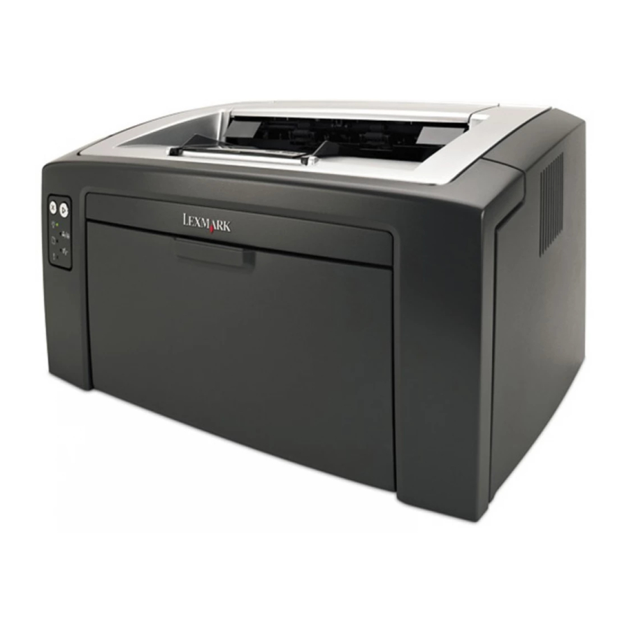
4506-1xx 1. General information The Lexmark™ E120 and E120n printers are monochrome laser printers designed for single users or small workgroups. Maintenance approach The diagnostic information in this manual leads to the correct field replaceable unit (FRU) or part. Use the error code charts, symptom index, and service checks to determine the symptom and repair the failure. -
Page 15: Front View
4506-1xx Front view Top door 50-sheet output bin Paper support Front door Priority feeder with adjustable guides Tray 1 cover/priority feeder paper path Tray 1 with adjustable guides Operator panel Slide and attached backstop Front door release button Rear view USB port Ethernet port (E120n only) -
Page 16: Specifications
To reduce printing problems and to receive the best print quality, try a sample of the media you are considering before buying large quantities. Refer to the Card Stock & Label Guide available on the Lexmark Web site at www.lexmark.com for more information about which print media provides optimum results. -
Page 17: Preprinted Forms And Letterhead
Use transparencies designed specifically for laser printers. Transparencies must be able to withstand temperatures of 185°C (365°F) without melting, discoloring, offsetting, or releasing hazardous emissions. We recommend Lexmark laser printer transparencies, part number 70X7240 for letter size transparencies; part number 12A5010 for A4 size transparencies. -
Page 18: Card Stock
Have any exposed adhesive when the flap is in the sealed position • Use only recommended paper. Refer to the Card Stock & Label Guide available on the Lexmark Web site at www.lexmark.com for more information about which paper provides optimum results for the current printing environment. -
Page 19: Tools
4506-1xx Tools The removal and adjustment procedures require the following tools and equipment: • Magnetic tip Phillips screwdrivers, large and small • Volt-ohmmeter Acronyms ASIC Application Specific Integrated Circuit Cyclic Redundancy Check Developer Roll (of toner cartridge/photoconductor system) DIMM Dual In-Line Memory Module EEPROM Erasable Electrically Programmable Read-Only Memory External Network Adapter... -
Page 20: Diagnostic Information
A description of a problem. See • Information from the operator panel of the printer – Lexmark E120—This model has an operator panel containing two lights and two buttons. For “Diagnostics—E120” on page 2-2. diagnostic information specific to these modes, see –... -
Page 21: Power-On Self Test (Post) Sequence
The printer cycles down into standby mode, and the Ready/Data light comes on solid. Overview of the operator panel—E120 The printer operator panel has two buttons and two lights. Lights indicate the status of the printer. Buttons are used to continue or cancel the current print job. -
Page 22: Light Patterns And Error Messages
4506-1xx Light patterns and error messages User attendance messages, paper jam errors, and service errors display an initial light pattern. This may be all the information you need. However, if you double-click on the panel, a second pattern may appear with more detailed information. -
Page 23: Primary, Secondary, And Tertiary Light Patterns
4506-1xx Primary, secondary, and tertiary light patterns The table below uses the following symbols to indicate solid, or blinking light patterns. When a number accompanies the blinking symbol, it refers to the number of times the light tuns off and on. Light continuously on Light off Light blinks continuously... - Page 24 4506-1xx Primary Secondary Tertiary Description Action Ready/ Ready/ Ready/ Data Data Data 35 Resource Save off; 1. Briefly press to temporarily disable insufficient memory Resource Save. 2. Set Link Buffer to Auto. 42 Cartridge region While the message is displayed, the following mismatch steps may be taken: 1.
- Page 25 4506-1xx Primary Secondary Tertiary Description Action Ready/ Ready/ Ready/ Data Data Data 88 Toner low 1. Replace the toner cartridge. 2. Briefly press to clear the message and continue printing. 201 Paper jam between 1. Open the rear and top doors, remove the input sensor and exit PC kit if necessary and clear the paper sensor...
- Page 26 4506-1xx Primary Secondary Tertiary Description Action Ready/ Ready/ Ready/ Data Data Data 930 Wrong printhead • Check all connections to the printhead. installed “Printhead • Replace the printhead. See removal” on page 4-12. 931 No first HYSNC 932 Lost HYSNC 933 Mirror motor locked 934 Mirror motor lost lock.
-
Page 27: Power-On Self Test (Post) Sequence
4506-1xx Primary Secondary Tertiary Description Action Ready/ Ready/ Ready/ Data Data Data “Controller 980 Engine is experiencing Replace the controller card. See card removal” on page 4-17. unreliable communications with the specified device. 981 Engine protocol violation is detected by the device. -
Page 28: Overview Of The Operator Panel-E120N
4506-1xx Overview of the operator panel—E120n The printer operator panel has two buttons and six lights (the Continue button is both a light and button). Lights indicate the status of the printer. Buttons are used to continue or cancel the current print job. When the printer is turned on, all lights cycle as a self test is performed. - Page 29 4506-1xx In the table below, white rows are primary codes, and secondary codes are in gray. The secondary light pattern is related to the primary light pattern immediately preceding it. Description/action “Ready/Power Saver” on page 2-11. Ready/Power Saver. See “Busy” on page 2-11.
-
Page 30: Additional Information-Primary Codes
4506-1xx PPDS font error Defective flash Insufficient defrag memory Network interface errors ENA connection lost Memory full Short paper “Service codes” on page 2-17 Service error see Additional information—primary codes The following tables explain the primary light patterns (or codes), the secondary error codes, what these codes mean, “Service and how to clear them. - Page 31 4506-1xx Primary codes—additional information (continued) Description/ Meaning Action Light pattern Waiting Printer is waiting until a print • Press and release to print the contents of timeout occurs, or until it the print buffer. receives additional data. • Press and release to cancel the print job.
- Page 32 4506-1xx Primary codes—additional information (continued) Description/ Meaning Action Light pattern Toner low The toner in the toner cartridge is • Send a print job. getting low. • Press to print the menu settings page for a list of current settings. •...
-
Page 33: Additional Information-Secondary Light Patterns
4506-1xx Primary codes—additional information (continued) Description/ Meaning Action Light pattern Service error The printer has a service error, Turn the printer off and back on. and printing has stopped. If the lights are still blinking, contact the next level of support. Press and release twice quickly to view the “Service primary... - Page 34 4506-1xx Secondary light patterns—additional information (continued) Description/ Meaning Action Light pattern 202 Paper jams as a printed job A paper jam has occurred as the Open the rear and top doors and clear the paper exits the printer. paper is exiting the printer. jam.
- Page 35 4506-1xx Secondary light patterns—additional information (continued) Description/ Meaning Action Light pattern 37 Insufficient collation area The printer memory does not have • Press to clear the message and continue the free space necessary to printing the job (the job may not print collate the print job.
-
Page 36: Service Codes
4506-1xx Secondary light patterns—additional information (continued) Description/ Meaning Action Light pattern Invalid network code The code in an internal print server Download valid network code to the internal has not been programmed, or the print server. programmed code is not valid. Service codes All service errors are indicated by all lights flashing as the primary notification or code. -
Page 37: Service Primary Code
4506-1xx Service primary code When this code appears, double-click to reveal the secondary codes. Light on Light off Light blinking Light blinking slowly Description/action This service primary code indicates that a secondary code is available. Service secondary error codes Secondary light pattern Service secondary light patterns Description/action 90x Software... -
Page 38: Controller Software
4506-1xx Controller software Controller software errors are in the 90x group/illegal trap (90x). Service tertiary light patterns—controller software (90x) Description/action When this secondary code is received, one of the following tertiary light patterns is available. 900 RIP error Replace the controller card or reload the engine code. -
Page 39: Fuser
4506-1xx Fuser “Fuser service check” on page 2-26 Codes 920 through 925 indicate a problem in the fuser (see for more information) or toner cartridge. Service tertiary light patterns—fuser (92x) Description/action When this secondary code is received, one of the following tertiary light patterns is available. -
Page 40: Lvps/Hvps Failure
4506-1xx Service tertiary light patterns—printhead, transport motor, or RIP/engine communication error (93x) Transport motor Replace the printer or call the next initial lock failure level of support. Transport motor lost lock RIP/engine communication error LVPS/HVPS failure Service tertiary light patterns—printhead, transport motor, or RIP/engine communication error (94x) Description/action Zero signal for fuser control has failed on LVPS. -
Page 41: Ram Memory Error
4506-1xx RAM memory error This error indicates RAM failure. Service tertiary light patterns—RAM memory error (96x) Description/action When this secondary code is received, the following tertiary light pattern is available. 960 RAM soldered on the board is bad • POR the printer. •... -
Page 42: Printer Symptom Table
4506-1xx Printer symptom table Symptom Action “Dead machine service check” on page 2-25. Dead machine (no power). Fan noisy or not working. Unplug the fan at CN404 on the LVPS/HVPS. Turn the printer on and verify +24 V dc on pin 1. If the voltage is not correct, replace the LVPS/ HVPS. -
Page 43: Service Checks
4506-1xx Service checks Service checks which involve measuring voltages on the LVPS/HVPS (low voltage power supply/ high voltage power supply board) should be performed with the printer positioned on its back side. Note: When you make voltage readings, always use frame ground unless another ground is specified. - Page 44 4506-1xx Action Controller card Check input voltages to the controller card from the LVPS/HVPS. assembly Warning: Check the following at CN402 on the LVPS/HVPS with the flat cable unplugged and the printer on. Do not check voltages on a flat cable due to potential damage to electrical components.
-
Page 45: Operator Panel Service Check
4506-1xx Operator Panel Service Check Operator panel Check the switches (buttons) with the printer off and operator panel cables (2 LED and 6 LED) disconnected. Warning: Do not • Check continuity between the ground and pin 6 (pins numbered from top) of J40 (operator panel card) while pressing . -
Page 46: Fuser Service Check
4506-1xx Fuser service check When toner is partially fused to the paper, it is usually caused by a low fuser temperature. Warning: Avoid handling the lamp as much as possible, as it is easily broken. Be careful not to touch the glass housing with bare hands because skin acids can weaken the glass. -
Page 47: Cold Fuser Service Check
4506-1xx Cold fuser service check Make sure the correct voltage lamp is installed. The voltage rating is stamped on one of the lamp contacts. Action If the fuser lamp comes on and a fuser failure light error code displays, be sure the thermistor is contacting the hot roll, and the thermistor cable is firmly seated in connector J2 on the controller card. -
Page 48: Lvps/Hvps Service Check
4506-1xx LVPS/HVPS service check LVPS portion of the LVPS/HVPS LVPS/HVPS Use the voltage meter to verify the appropriate voltage at the printer end of the power cable. Disconnect the power cable from the printer and the fuser cable (CN403) and check the following: •... -
Page 49: Paper Feed Service Checks
4506-1xx Paper feed service checks Paper jam error indication during POST Action Fuser (exit sensor) If the exit sensor flag is not resting within the paper exit sensor during POST, the printer displays a paper jam message. Make sure the flag is operating freely and Paper pick assembly is correctly installed. -
Page 50: Paper Never Picks
4506-1xx Paper never picks Action Paper pick assembly Open the left cover, and verify the solenoid and clutch are functioning when an attempt is made to feed the paper. • If the shaft of the assembly rotates and paper does not move, remove the picking assembly and inspect the pick roll and pad. -
Page 51: Paper "Trees," Wrinkles, Stacks Poorly, Or Curls
‘dirty’ print. Extreme environmental conditions, temperatures, and humidity will affect the print quality. Using print quality test pages To help isolate print quality problems, like streaking, print test pages using the print quality test pages. Model E120 To print the print quality test pages: Enter Diagnostics mode: Turn off the printer. -
Page 52: Blank Page
4506-1xx Model E120n To print the print quality test pages: Enter the Configuration menu. Turn off the printer. Open the front access cover. Turn on the printer while pressing and holding When the light stays on, close the cover. Wait (approximately 10 seconds) until the printer drive activates. Slowly press and release three times until the lights come on. -
Page 53: Black Page
4506-1xx Black page Note: Incorrect laser exposure or incorrect charging of the photoconductor causes an all black page. Always verify the same results from a different toner cartridge assembly and developer before proceeding. Action PC kit (not a FRU) Check the three electrical contacts at the right rear of the toner cartridge assembly for contamination or damage. -
Page 54: Partial Blank Image/White Spots (No Periodic Pattern)
4506-1xx Partial blank image/white spots (no periodic pattern) Action Toner cartridge (not a Remove the toner cartridge assembly, and gently shake the assembly to evenly FRU) distribute the toner. Check to make sure the dust cover is in place and in use. If the dust cover is not in place, spotting can result. -
Page 55: Light Print
4506-1xx Light print Action Toner cartridge (not a Print a menu page (press and release when the printer is in the ready state) FRU) and check for the correct media type setting. Check darkness in the printer driver. Make sure the toner cartridge and PC kit are installed correctly and that the toner cartridge is not low on toner. -
Page 56: Toner On Back Of Page
4506-1xx Toner on back of page Action PC Kit (not a FRU) Print a menu page (press and release when the printer is in the ready state) and check settings for the correct media type. Inspect the overall paper path for signs of spilled toner. Gently clean the contaminated areas with a soft cloth. - Page 57 4506-1xx Symptom Cause Solution Streaked vertical lines • The toner is smeared before • If paper is stiff, try feeding from the fusing to the paper. priority feeder. • The toner cartridge is defective. • Replace the toner cartridge. • The PCU cleaner is full. •...
- Page 58 4506-1xx Symptom Cause Solution Toner rubs off paper • The Paper Texture setting is • Change the Paper Texture from easily when sheets are wrong for the type of paper or Normal to Smooth or Rough. handled specialty media being used. This setting can be changed using •...
- Page 59 4506-1xx Symptom Cause Solution Specifically located The long-life photoconductor kit is Replace the long-life photoconductor ghost images exhausted. kit. Note: From the top of the image to the top of the ghost is 71mm. Grouped streaks along The long-life photoconductor kit is Replace the long-life photoconductor the left or right (not exhausted.
-
Page 60: Printhead Service Check
4506-1xx Symptom Cause Solution Skewed print • The tray guide is not in the • Reposition the guide to fit lightly correct position. against the paper stack. (Print is inappropriately • The priority feeder guides are not • Reposition the priority feeder slanted.) in the correct position for the guides to fit lightly against the print... -
Page 61: Transfer Roll Service Check
4506-1xx Transfer roll service check Action Check the transfer roll area for debris, and clean the area as necessary. Verify continuity between the spring below the left side (facing the rear of the printer) bearing and the conical compression spring on the left side of the door. Verify continuity in the spring and the cable connection on the LVPS/HVPS. -
Page 62: Diagnostic Aids
There are different test menus that can be accessed during POR to identify problems with the printer. Service menus—E120 Printing menus To enter Diagnostics mode, turn off the printer, open the front access cover, press and hold while turning on the printer. -
Page 63: Diagnostics Mode Printout Sample
4506-1xx Diagnostics mode printout sample Service Manual... -
Page 64: Diagnostics Mode Descriptions
4506-1xx Diagnostics mode descriptions Development Menu item Use setting to Value Print quality pages Print the print quality test pages and history information by pressing and holding until the lights flash. Help isolate print quality problems, such as streaking. Four or more pages print: •... -
Page 65: Diagnostics Mode Printout Sample
4506-1xx Diagnostics mode printout sample Service Manual... -
Page 66: Diagnostics Mode Descriptions
4506-1xx Diagnostics mode descriptions To enter Diagnostics mode, do the following: Turn the printer off. Open the front access cover. Press and hold while turning the printer on. Close the cover when the light displays. Print menus by pressing and holding until the lights flash. -
Page 67: Network
4506-1xx Network Menu item Use this setting to Value History Print a history of errors. (same as Print History) Press and hold until the lights flash to print. Mark History Append a tag to the history report to indicate the Mark most recent crashes. -
Page 68: Configuration Menu Printout Sample
4506-1xx Configuration menu printout sample Diagnostic aids... -
Page 69: Configuration Menu Descriptions
4506-1xx Configuration menu descriptions To enter the Configuration menu, turn off the printer, open the front access cover, turn on the printer while pressing and holding , and close the cover once the light displays. Print menus by pressing and holding until the lights flash. -
Page 70: Setup
4506-1xx Setup Use the Setup menu to configure how the printer formats the end of a line depending on the computer system being used. Menu item Use this setting to Values Demo Mode Put the printer into demo mode where internal Deactivate (default) sheets print with each press of Activate... -
Page 71: Network
4506-1xx Network Use the network menu to change printer settings on jobs sent through a network port (either standard network or network opt <x>). Menu item Use setting to Values NPA Mode Send print jobs to the printer and query printer status information simultaneously. -
Page 72: Repair Information
4506-1xx 4. Repair information Warning: Read the following before handling electronic parts. Handling ESD-sensitive parts Many electronic products use parts that are known to be sensitive to electrostatic discharge (ESD). To prevent damage to ESD-sensitive parts, use the following instructions in addition to all the usual precautions, such as turning off power before removing logic boards: •... -
Page 73: Adjustment Procedures
Note: In order to limit the number of printouts, place only one sheet at a time in the main tray. For the E120 model—The E120 can be adjusted in the same manner as the E120n. However, this model does not print the same sheet. You may have to find or create a page with lines going horizontally across the page. - Page 74 4506-1xx If the top margin of the grid lines of the right flap is greater than the top margin of the grid lines on the left flap, adjust the printhead clockwise relative to the printer and recheck. See the left side of the figure below. Adjust the printhead counterclockwise if the left side grid lines extend below the right side.
-
Page 75: Removal Procedures
4506-1xx Removal procedures CAUTION: Remove the power cord from the printer or electrical outlet before you connect or disconnect any cable, electronic board, or assembly for personal safety and to prevent damage to the printer. Disconnect any connections between the printer and PCs/peripherals. Note: Some removal procedures may require removing cable ties. -
Page 76: Main Tray Removal
4506-1xx Main tray removal “Tray cover removal” on page 4-4. Remove the tray cover. See Align the front of the printer with the front edge of the table. Put pressure with your thumb in the center of the tray and pull out. Left cover removal Open the rear door and remove the screw (A). - Page 77 4506-1xx Remove the screw (B). Pull the cover away from the printer and lift to remove it. Service Manual...
-
Page 78: Right Cover Removal
4506-1xx Right cover removal Open the rear door and remove the lower right screw (A). Open the front door and remove the screw (B). Repair information... -
Page 79: Front Door Assembly Removal
4506-1xx Pull the front of the cover to unlatch (B), pull the bottom out, and lift the cover to removeit. Front door assembly removal “Left cover removal” on page 4-5. Remove the left cover. See “Right cover removal” on page 4-7. -
Page 80: Top Cover Assembly Removal
4506-1xx Top cover assembly removal “Front door assembly removal” on page 4-8. Remove the front door assembly. See Remove the two screws (A) from the front of the printer. Remove the two screws (B) from the back of the printer. Repair information... - Page 81 4506-1xx Lift the front of the cover and unhook the rear. 4-10 Service Manual...
- Page 82 4506-1xx Reinstallation note: Close the top door before reinstalling the top cover. When the top cover is in place, open the top door and press vertically on the front leg of the flag. It should rotate downward and return by the force of the cantilever spring in the cover.
-
Page 83: Printhead Removal
4506-1xx Printhead removal “Top cover assembly removal” on page 4-9. Remove the top cover. See Remove the three screws (A). Disconnect the printhead cables at J12 and J13 on the controller card. Remove the printhead. Note: After reinstalling the printhead, check the alignment. If necessary, perform the “Printhead assembly adjustment”... -
Page 84: Rear Door Assembly
4506-1xx Rear door assembly Note: Be careful not to touch the transfer roll during this removal. Open the rear door. Remove the two screws (A). Remove the transfer card cover (B). Press the right side door stop (C) to the left and rotate the cover slightly to free the stop. Detach the right hinge from its pivot (D) with a short, quick motion. -
Page 85: Transfer Card And Input Sensor Assembly Removal
4506-1xx Press the left side door stop (E) to free it from the printer. Pull out the left side of the rear door. Transfer card and input sensor assembly removal “Left cover removal” on page 4-5. Remove the left cover. See “Rear door assembly”... -
Page 86: Paper Pick Assembly Removal
4506-1xx Disconnect the cable (B) from the controller card at J9. Remove the card and cable assembly carefully by sliding the cable through the retainer (C). Paper pick assembly removal “Transfer card and input sensor assembly Remove the transfer card and input sensor assembly. See removal”... - Page 87 4506-1xx Press the locking tab (B) on the gear hub while sliding the gear from the shaft. Remove the gears and spring (C) from the shaft. Disconnect the cable (D) from the controller card at J10. Remove the paper pick assembly. 4-16 Service Manual...
-
Page 88: Controller Card Removal
4506-1xx Controller card removal Warning: Do not replace the operator panel and controller card at the same time. Each card contains the printer settings. When either of these cards is new, it obtains some of the settings from the other card. -
Page 89: Operator Panel Removal (All Models)
4506-1xx Operator panel removal (all models) Warning: Do not replace the operator panel and controller card at the same time. Each card contains the printer settings. When either of these cards is new, it obtains some of the settings from the other card. -
Page 90: Lvps/Hvps Removal
4506-1xx LVPS/HVPS removal “Right cover removal” on page 4-7. Remove the right cover. See Disconnect the three cables (A) connected to the LVPS/HVPS card. Remove the four common screws (B) and the unique screw (C). Squeeze the latch (D) to free the card. 4-19 Repair information... -
Page 91: Fuser Removal
4506-1xx Fuser removal “Top cover assembly removal” on page 4-9. Remove the top cover assembly. See Remove the two screws (A). Disconnect the cables from the LVPS/HVPS (CN403) and the controller card (J1 and J2). Remove the fuser along with the sensor and cables. 4-20 Service Manual... -
Page 92: Locations And Connections
4506-1xx 5. Locations and connections Locations Front view Top door 50-sheet output bin Paper support Front door Priority feeder with adjustable guides Tray 1 cover/priority feeder paper path Tray 1 with adjustable guides Operator panel Slide and attached backstop Front door release button Rear view USB port... -
Page 93: Connectors
4506-1xx Connectors Controller card Service Manual... - Page 94 4506-1xx Controller card connector pin values (only J2, thermistor, and J6 LVPS/HVPS connected) Connector Pin # Value J1 Exit sensor +5 V dc Ground +5 V dc Ground J2 Thermistor Ground J3 toner cartridge +5 V dc J4 Main motor +5 V dc +5 V dc +5 V dc...
-
Page 95: Lvps/Hvps Card
4506-1xx LVPS/HVPS card Service Manual... - Page 96 4506-1xx LVPS/HVPS pin values (turn the switch on and unplug the cables except for the AC input) Connector Pin # Value CN402 +24 V dc +24 V dc +24 V dc +24 V dc +24 V dc +24 V dc (F403Fused) Ground Ground...
- Page 97 4506-1xx Service Manual...
-
Page 98: Preventive Maintenance
4506-1xx 6. Preventive maintenance The E120 and E120n do not require preventive maintenance. Preventive maintenance... - Page 99 4506-1xx Service Manual...
-
Page 100: Parts Catalog
PP: (Parts Packet) in the parts description column indicates the part is contained in a parts packet. • Model information used in the parts catalog: Abbreviation Machine type Network Description used and model capability E120 4506-100 Lexmark E120 Non-network E120n 4506-110 Lexmark E120n Network Parts catalog... -
Page 101: Assembly 1: Covers
4506-1xx Assembly 1: Covers Service Manual... - Page 102 4506-1xx Asm- Part Units/ Units/ Description index number mach 1—1 40X1293 Rear door assembly 40X1295 Output tray extender 40X1290 Top cover assembly 40X1289 Right cover 40X1294 Main tray assembly 40X1291 Tray cover 40X1292 Front door assembly 40X1288 Left cover Parts catalog...
-
Page 103: Assembly 2: Electronics
4506-1xx Assembly 2: Electronics Service Manual... - Page 104 Transfer card and input sensor 40X1284 Printhead assembly, including cables 40X1278 LVPS/HVPS, 110 V 40X1279 LVPS/HVPS, 220 V 40X1282 Operator panel (2 button, 6 light), E120n 40X1283 Operator panel (2 button, 2 light), E120 40X1280 Controller card, E120 40X1281 Controller card, E120n Parts catalog...
-
Page 105: Assembly 3: Frame
4506-1xx Assembly 3: Frame Service Manual... - Page 106 4506-1xx Asm- Part Units/ Units/ Description index number mach 3—1 40X1287 Transfer roll assembly 40X1276 Fuser assembly, 110 V 40X1277 Fuser assembly, 220 V 40X1298 Fuser assembly, 100 V 40X1285 Paper pick assembly 40X1299 Screws, parts packet Parts catalog...
-
Page 107: Assembly 4: Miscellaneous
4506-1xx Assembly 4: Miscellaneous Asm- Part Units/ Units/ Description index number mach 40X0289 Power cord—U.S.A. and Canada 40X0271 Power cord, 8 ft.—United Kingdom 40X0274 Power cord, 6 ft.—Switzerland 40X0275 Power cord, 6 ft.—Israel 40X0276 Power cord, 6 ft., straight—South Africa 40X0277 Power cord, 6 ft., straight—Brazil 40X0278... -
Page 108: Index
4506-1xx Index diagnostic information diagnostics mode—E120 abbreviations Defaults acronyms menus adjustments, printhead assembly Print Quality Pages alignment, printhead printing menu Auto CR After LF, E120n printout sample Auto LF After CR, E120n table of light patterns diagnostics mode—E120n Development buttons... - Page 109 2-14 E120n 2-29 paper feed service check labels tips on preventing left cover removal paper recommendations letterhead parts catalog light patterns, E120 covers 2-11 additional information—primary codes electronics description frame 2-17 light patterns, E120n—service codes power-on self test (POST) locations...
- Page 110 4506-1xx 2-34 Transfer roll error codes safety information E120 secondary error codes 2-18 2-19 E120n 2-15 complex page parts catalog 2-16 error communicating with the host computer 4-12 removal 2-16 insufficient collation area 2-41 service check 2-16 invalid engine code...
- Page 111 4506-1xx Service Manual...
-
Page 112: Part Number Index
Operator panel (2 button, 2 light), E120 - - - - - - - - - - - - - - - - - - - - - - - - - - - - - - - - -... - Page 113 4506-1xx Service Manual...
- Page 114 Print defects guide Match a set of repeating defects on a print job to the marks on one of the vertical lines. The line that best matches the defect on the print job indicates which particular part may be causing the defect. Notes: Defects in graphics will be spaced very slightly further apart for the print cartridge and PC kit but the difference will not be noticed between two adjacent defects.
Need help?
Do you have a question about the E120 and is the answer not in the manual?
Questions and answers