Table of Contents
Advertisement
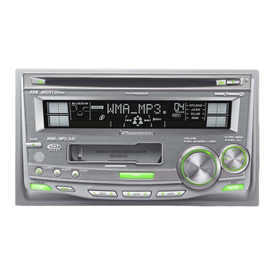
MULTI-CD CONTROL DSP HIGH POWER CD/MP3/WMA/
CASSETTE PLAYER WITH FM/AM TUNER
FH-P4200MP
FH-P4200MP
FH-P4200MP
This service manual should be used together with the following manual(s):
Model No.
Order No.
CX-3158
CRT3394
CX-1011
CRT2406
Dolby noise reduction manufactured under license from Dolby Laboratories Licensing
Corporation.
"Dolby" and the double-D symbol are trademarks of Dolby Laboratories Licensing Cor-
poration.
For details, refer to "Important Check Points for Good Servicing".
PIONEER CORPORATION
PIONEER ELECTRONICS (USA) INC. P.O. Box 1760, Long Beach, CA 90801-1760, U.S.A.
PIONEER EUROPE NV Haven 1087, Keetberglaan 1, 9120 Melsele, Belgium
PIONEER ELECTRONICS ASIACENTRE PTE. LTD. 253 Alexandra Road, #04-01, Singapore 159936
PIONEER CORPORATION 2005
Mech.Module
S10.1AAC
CD Mech. Module:Circuit Description, Mech. Description, Disassembly
3L
Cassette Mech. Module:Mech. Description, Disassembly, Adjustment
4-1, Meguro 1-chome, Meguro-ku, Tokyo 153-8654, Japan
FH-P4200MP/XU/UC
/XU/ES
/XU/CN
Remarks
ORDER NO.
CRT3417
/XU/UC
K-ZZD.FEB. 2005 Printed in Japan
Advertisement
Table of Contents

Related Manuals for Pioneer FH-P4200MP/XU/UC


Summary of Contents for Pioneer FH-P4200MP/XU/UC
- Page 1 PIONEER CORPORATION 4-1, Meguro 1-chome, Meguro-ku, Tokyo 153-8654, Japan PIONEER ELECTRONICS (USA) INC. P.O. Box 1760, Long Beach, CA 90801-1760, U.S.A. PIONEER EUROPE NV Haven 1087, Keetberglaan 1, 9120 Melsele, Belgium PIONEER ELECTRONICS ASIACENTRE PTE. LTD. 253 Alexandra Road, #04-01, Singapore 159936 PIONEER CORPORATION 2005 K-ZZD.FEB.
-
Page 2: Safety Information
4. After replacing the pickup unit, be sure to check the 2. Before disassembling the unit, be sure to turn off grating. the power. Unplugging and plugging the connectors during power-on mode may damage the ICs inside the unit. FH-P4200MP/XU/UC... - Page 3 To protect products from damages or failures during transit, the shipping mode should be set or the shipping screws should be installed before shipment. Please be sure to follow this method especially if it is specified in this manual. FH-P4200MP/XU/UC...
-
Page 4: Table Of Contents
7. GENERAL INFORMATION ..........................65 7.1 DIAGNOSIS ............................. 65 7.1.1 DISASSEMBLY ............................. 65 7.1.2 CONNECTOR FUNCTION DESCRIPTION ..................69 7.2 PARTS..............................70 7.2.1 IC ................................70 7.2.2 DISPLAY ............................... 79 7.3 OPERATIONAL FLOW CHART ....................... 81 7.4 CLEANING............................... 82 8. OPERATIONS ..............................83 FH-P4200MP/XU/UC... -
Page 5: Specifications
1. SPECIFICATIONS FH-P4200MP/XU/UC... - Page 6 FH-P4200MP/XU/UC...
- Page 7 FH-P4200MP/XU/UC...
-
Page 8: Exploded Views And Parts List
• Screw adjacent to mark on the product are used for disassembly. • For the applying amount of lobricants or glue, follow the instructions in this manual. (In the case of no amount instructions,apply as you think it appropriate.) 2.1 PACKING FH-P4200MP/XU/UC... - Page 9 Accessory Assy CEA4321 Remote Control Unit CXC3174 Screw BMZ50P080FTC Panel See Contrast table(2) Screw CMZ50P080FTC (2) CONTRAST TABLE FH-P4200MP/XU/UC, FH-P4200MP/XU/ES and FH-P4200MP/XU/CN are constructed the same except for the fol- lowing: Mark Description FH-P4200MP/XU/UC FH-P4200MP/XU/ES FH-P4200MP/XU/CN Contain Box YHD5006 YHD5005 YHD5007...
-
Page 10: Exterior
2.2 EXTERIOR 55 50 49 48 53 66 FH-P4200MP/XU/UC... - Page 11 CKS3124 IC(IC802) NJM2388F84 Connector(CN170) CKS3408 Transistor(Q814) 2SD2396 Plug(CN900) CKS3537 (2) CONTRAST TABLE FH-P4200MP/XU/UC, FH-P4200MP/XU/ES and FH-P4200MP/XU/CN are constructed the same except for the fol- lowing: Mark Description FH-P4200MP/XU/UC FH-P4200MP/XU/ES FH-P4200MP/XU/CN CNV6727 Not used Not used CD Mechanism Module(S10.1 AAC) CXK5679...
-
Page 12: Cd Mechanism Module
2.3 CD MECHANISM MODULE 1GEM1024 2GEM1045 3GEM1035 FH-P4200MP/XU/UC... - Page 13 Screw(M2x5) EBA1028 CND1909 Screw JFZ20P020FTC Lever CND2032 Screw JGZ17P022FTC ••••• Lever CNC9984 Sheet CNM8134 Washer YE20FTC Collar CNV8447 Pickup Unit(P10)(Service) CXX1647 Guide CNV8448 Screw IMS26P030FTC CNV8403 Spring CBL1635 Clamper CNV8372 Rack CNV8374 Holder CNV8376 Connector(CN902) CKS2193 Holder CNV8377 CNV8378 FH-P4200MP/XU/UC...
-
Page 14: Cassette Mechanism Module
2.4 CASSETTE MECHANISM MODULE For grease application, refer to the service manual for CX-1011 (CRT2406). FH-P4200MP/XU/UC... - Page 15 CKS3540 Gathering PCB ENX1065 Motor Unit(M1) EXA1655 Motor EXM1044 Head Assy(HD1) EXA1592 Motor Unit(M2) EXA1654 Screw BMZ20P022FTC Bracket ENC1528 Chassis Unit EXA1615 Pinch Holder Unit EXA1608 Pinch Roller ENV1518 Pinch Holder Unit EXA1607 Pinch Roller ENV1518 Reel Unit EXA1625 FH-P4200MP/XU/UC...
-
Page 16: Block Diagram And Schematic Diagram
L-ch VCC8 IC251 CSMDL TAPE Lch HA12228F MSIN,DIRO,PLAY,MTL,NR, L-ch BU14V POS,ES,CM,SC1,SC2 CN254 MECHANISM DRIVER stby MOTOR STBY load IC351 LOAD PA2020B CN255 MAIN MOTOR CN253 CN256 Q101 EGN1004 REEL SENSE S102 S103 S101 MODE 70µs LOAD SENSOR UNIT LCDPW FH-P4200MP/XU/UC... -
Page 17: Keyboard Unit
SEG1-56 DPDT S1301 LOADSW /RESET /RESET RESET DPDT RESET LCD DRIVER/ X1301 KEY CONTROLLER KYDT KYDT KYDT KYDT IC1302 RESET OSC2 PEG079A IC1304 reset X1302 Q811 S-80842CNUA-B83 BKLT+B BKLT+B OSC1 LCD BACKLIGHT PVD8V Q813 BU14V LCDPW /DIM Q1101 LCDPW FH-P4200MP/XU/UC... -
Page 18: Overall Connection Diagram(Guide Page)
CD5VON Not used For resistors and capacitors in the circuit diagrams, their resistance valu capacitance values are expressed in codes: FM/AM ANTENNA Ex. *Resistors Code Practical value 12k ohms 10k ohms *Capacitors Code Practical value 0.01uF 101/10 100uF/10V CN1301 FH-P4200MP/XU/UC... - Page 19 The > mark found on some component parts indicates the importance of the safety factor of the part. Therefore, when replacing, be sure to use parts of identical designation. : The power supply is shown with the marked box. FH-P4200MP/XU/UC...
- Page 20 FH-P4200MP/XU/UC...
- Page 21 FH-P4200MP/XU/UC...
- Page 22 FH-P4200MP/XU/UC...
- Page 23 FH-P4200MP/XU/UC...
-
Page 24: Keyboard Unit
FUNCTION → DISP CD EJECT ↓ VOLUME/ SOURCE REMOTE CONTR SENSOR RESET GREEN LED D1225-D1228 UC ,ES :SML-310PT (GREEN LED) CN:CL-190UB2-X (BLUE LED) UC ,ES : 271 CN : 181 UC ,ES : 271 CN : 181 ES,CN CN900 FH-P4200MP/XU/UC... - Page 25 MOTE CONTROL LCD DRIVER, SENSOR KEY CONTROLLER 10.0MHz RESET IC CN1301 CN900 FH-P4200MP/XU/UC...
-
Page 26: Cd Mechanism Module
The > mark found on some component parts indicates the importance of the safety factor of the part. Therefore, when replacing, be sure to use parts of identical designation. 100K M1 CXC4440 SPINDLE MOTOR M2 CXB8933 LOADING /CARRIAGE CD DRIVER MOTOR FH-P4200MP/XU/UC... - Page 27 The underlined indicates the switch position. SIGNAL LINE FOCUS SERVO LINE TRACKING SERVO LINE CARRIAGE SERVO LINE SPINDLE SERVO LINE CD CORE UNIT 3.3V REGULATOR CN100 SRAMLEVEL2 MICRO COMPUTER 3V REGULATOR CN101 SRAMLEVEL1 SRAMLEVEL0 100K TYPE_A/D & LRCK DOUT ⁄ FH-P4200MP/XU/UC...
- Page 28 FH-P4200MP/XU/UC...
- Page 29 FH-P4200MP/XU/UC...
- Page 30 FH-P4200MP/XU/UC...
- Page 31 FH-P4200MP/XU/UC...
- Page 32 7 SIN 500mV/div 200mV/div 1V/div @ TE 500mV/div 9 TIN 500mV/div CD-ROM play operation(Regular track Jump) Spindle waveform during play operation Spindle waveform during play operation (Wider) Ref.: Ref.: Ref.: REFO REFO REFO Mode: Mode: Mode: Normal Normal Normal FH-P4200MP/XU/UC...
- Page 33 500mV/div 5V/div 500mV/div 9 TIN 3 12SNS 9 TIN 500mV/div 5V/div 500mV/div 4 LOEJ 5V/div CD-ROM→CD-DA mode change(Band key) 8 cm CD Eject operation CD-DA→CD-ROM mode change(Band key) Ref.: Ref.: Ref.: REFO REFO Mode: Mode: Mode: Normal Normal Normal FH-P4200MP/XU/UC...
- Page 34 Normal Normal Normal ( CD3VON 8 CIN 5V/div 200ms/div 500mV/div 100ms/div & LRCK @ TE 2V/div 500mV/div ) LRCKOK ⁄ EMPH 2V/div 5V/div 12 cm CD Eject operation Tracks Jump(EMPH : OFF→ON) Ref.: Ref.: REFO Mode: Mode: Normal Normal FH-P4200MP/XU/UC...
- Page 35 FH-P4200MP/XU/UC...
-
Page 36: Cassette Mechanism Module
IC251 ser/REP RIN(L) Fwd-R HA12228F RIN(R) MSOUT C405 R033 Fwd-L EQ AMP, R404 270K MSDET FIN(R) C404 Vref2 DOLBY B NR R403 MAOUT FIN(L) MSGV(R) NFI(L) HEAD ASSY EXA1592 TEST TAPE NCT-150 C255 (400Hz, 200nWb/m) C272 CN251 -8.24dBs±1dB CN700 FH-P4200MP/XU/UC... - Page 37 S102 DRIVER load S101 LOAD ESG1007 C405 R033 R404 270K CN254 MOTOR UNIT (SUB MOTOR) VCC2 EXA1654 R374 0R0 C356 R01 C355 R1 SWITCHES: SENSOR UNIT S101:LOAD SWITCH..EJECT-PLAY S102:MODE SWITCH....ON-OFF S103:70µs SWITCH....ON-OFF CN700 The underlined indicates the switch position. FH-P4200MP/XU/UC...
-
Page 38: Pcb Connection Diagram
CORD ASSY include all necessary parts for several destination. For further information for respective destinations, be sure to check with the schematic dia- gram. 2.Viewpoint of PCB diagrams Capacitor Connector SIDE A SIDE B P.C.Board Chip Part CN901 CN902 FH-P4200MP/XU/UC... - Page 39 SIDE A CORD ASSY(FH-P4200MP/XU/UC) NON-FAD/SUB W. FM/AM ANTENNA L-CH R-CH IP-BUS CN251 CN1301 FRONT FH-P4200MP/XU/UC...
- Page 40 TUNER AMP UNIT TEST PCL1 FH-P4200MP/XU/UC...
- Page 41 SIDE B FH-P4200MP/XU/UC...
-
Page 42: Keyboard Unit
4.2 KEYBOARD UNIT KEYBOARD UNIT SIDE A FH-P4200MP/XU/UC... - Page 43 KEYBOARD UNIT SIDE B CN900 FH-P4200MP/XU/UC...
-
Page 44: Cd Core Unit
4.3 CD CORE UNIT CORE CD CORE UNIT SIDE A LOADING /CARRIAGE MOTOR SPINDLE MOTOR CN101 HOME CN100 REFO1 FH-P4200MP/XU/UC... - Page 45 CD CORE UNIT SIDE B 12EJ DSCSNS FH-P4200MP/XU/UC...
-
Page 46: Cassette Mechanism Module
4.4 CASSETTE MECHANISM MODULE CN700 SIDE A DECK UNIT CN251 C271 DECK UNIT SIDE B HEAD ASSY IC,Q VR302 CN254 CN255 CN253 IC351 CN252 IC251 Q351 Q352 VR301 CN256 FH-P4200MP/XU/UC... - Page 47 SENSOR UNIT S101 LOAD S103 70µs S102 MODE CN256 Q101 REEL SENSE CN253 FH-P4200MP/XU/UC...
-
Page 48: Electrical Parts List
L 200 (B,59,53) Inductor CTF1379 Q 804 (A,72,17) Transistor 2SB1132 Q 805 (A,38,14) Transistor 2SA1797 L 201 (B,50,60) Inductor CTF1379 L 202 (A,40,39) Inductor CTF1306 Q 807 (A,66,15) Transistor DTC124EU L 203 (B,74,59) Inductor CTF1379 Q 808 (A,51,13) Transistor DTC124EU FH-P4200MP/XU/UC... - Page 49 R 172 (B,124,134) RS1/16S181J R 269 (A,75,77) RS1/16S103J R 173 (A,113,83) RS1/16S101J R 270 (A,66,90) RS1/16S683J R 174 (B,126,124) RS1/16S223J R 271 (A,47,90) RS1/16S683J R 175 (A,110,80) RS1/16S101J R 272 (A,57,90) RS1/16S683J R 176 (B,124,126) RS1/16S102J R 273 (B,69,87) RS1/16S473J FH-P4200MP/XU/UC...
- Page 50 R 601 (A,95,55) RS1/16S221J R 817 (A,106,139) RS1/16S473J R 602 (A,120,19) RS1/16S102J R 818 (B,122,135) RS1/16S101J R 603 (B,101,38) RS1/16S473J R 819 (A,10,19) RAB4C101J R 604 (A,125,17) RS1/16S124J R 820 (A,87,73) RS1/16S152J R 605 (B,100,43) RS1/16S473J R 821 (A,119,124) RS1/16S820J FH-P4200MP/XU/UC...
- Page 51 C 218 (B,57,46) CKSRYB105K10 C 301 (A,78,116) CFTNA224J50 C 219 (B,72,53) CCSRCH101J50 C 302 (A,65,116) CFTNA224J50 C 221 (A,60,73) CKSRYB222K50 C 303 (A,69,116) CFTNA224J50 C 222 (A,45,38) CCSRCH101J50 C 308 (A,83,133) CEJQ330M10 C 223 (A,59,68) CKSRYB105K10 C 309 (A,56,132) CKSRYB105K10 FH-P4200MP/XU/UC...
- Page 52 C 814 (B,116,131) CKSRYB104K50 D 1221 (A,88,91) LED SML-310PT C 815 (B,112,135) CKSRYB103K50 D 1222 (A,69,119) LED SML-310PT C 816 (B,73,68) CKSRYB103K50 C 817 (B,74,53) CKSRYB103K50 D 1223 (A,59,135) LED SML-310PT D 1225 (A,78,68) LED SML-310PT C 818 (B,152,30) CKSRYB103K50 FH-P4200MP/XU/UC...
- Page 53 CKSRYB474K10 R 1220 (B,86,61) RS1/16S271J C 1321 (B,27,157) CCSRCH220J50 R 1222 (B,86,63) RS1/16S331J C 1322 (B,21,158) CCSRCH180J50 R 1224 (B,86,64) RS1/16S331J C 1323 (B,59,149) CKSRYB222K50 R 1226 (B,86,66) RS1/16S271J R 1227 (B,86,68) RS1/16S331J Unit Number:YWM5066(CN) R 1228 (B,86,70) RS1/16S331J FH-P4200MP/XU/UC...
- Page 54 R 1326 (B,25,151) RS1/16S0R0J S 1210 (A,73,39) Push Switch CSG1155 R 1328 (B,20,161) RS1/16S473J S 1211 (A,72,85) Push Switch CSG1155 S 1212 (A,89,99) Push Switch CSG1155 R 1329 (B,37,149) RS1/16S473J R 1330 (B,40,149) RS1/16S473J S 1213 (A,80,154) Push Switch CSG1155 FH-P4200MP/XU/UC...
- Page 55 CTF1306 R 751 (A,45,61) RS1/16SS102J L 904 (B,38,48) Inductor CTF1306 R 754 (B,48,60) RS1/16SS102J X 701 CSS1652 (A,59,53) Ceramic Resonator 4.00MHz R 755 (A,43,61) RS1/16SS102J R 765 (B,51,40) RAB4CQ221J S 901 (A,15,43) Switch(HOME) CSN1067 S 903 (B,53,100) Switch(DSCSNS) CSN1068 FH-P4200MP/XU/UC...
- Page 56 C 707 (A,36,45) CKSSYB104K10 C 712 (A,22,42) CKSRYB224K16 C 403 CKSRYB223K25 C 404 CKSRYB103K50 C 714 (B,60,45) CKSSYB104K10 C 405 CKSRYB333K16 C 716 (A,61,40) CKSSYB103K16 C 722 (B,52,48) CKSQYB475K6R3 C 723 (A,26,41) CKSRYB105K10 Unit Number:EWM1036 C 903 (B,56,70) CKSSYB471K50 FH-P4200MP/XU/UC...
- Page 57 Unit Name:Sensor Unit MISCELLANEOUS S 101 Switch(LOAD) ESG1007 S 102 Switch(MODE) ESG1007 S 103 Switch(70µs) ESG1007 Q 101 Photo-reflector EGN1004 Miscellaneous Parts List Pickup Unit(P10)(Service) CXX1647 Motor Unit(SPINDLE) CXC4440 CXB8933 Motor Unit(LOADING/CARRIAGE) Motor Unit(MAIN) EXA1655 Motor Unit(SUB) EXA1654 Head Assy EXA1592 FH-P4200MP/XU/UC...
-
Page 58: Adjustment
1k ohms in series. • The load and eject operation is not guarantied with the mechanism upside down. If the mechanism is blocked due to mistaken eject operation, reset the product or turn off and on the ACC to restore it. FH-P4200MP/XU/UC... - Page 59 → → TYP(1X) TYP(2X) TRK 22 MIN 22 SEC 22 TRK 11 MIN 11 SEC 11 TRK 11 MIN 11 SEC 11 TRK 22 MIN 22 SEC 22 As for the double speed (2x), audio output cannot be supported FH-P4200MP/XU/UC...
-
Page 60: Checking The Grating After Changing The Pickup Unit
Because of eccentricity in the disc and a slight misalignment of the clamping center the grating waveform may be seen to "wobble" ( the phase difference changes as the disc rotates). The angle specified above indicates the average angle. • Hint Reloading the disc changes the clamp position and may decrease the "wobble". FH-P4200MP/XU/UC... - Page 61 Ech → Xch 20mV/div, AC Grating waveform Fch → Ych 20mV/div, AC 0° 30° 45° 60° 75° 90° FH-P4200MP/XU/UC...
-
Page 62: Error Mode
If TOC can’t be read, error wouldn’t occur, but mechanism still continues its operation. The upper digits of error code is mainly classified by 3 kinds as follows: 1x: Setup related error, 3x: Search related error, Ax: Other errors. FH-P4200MP/XU/UC... -
Page 63: Dolby B Nr Adjustment
Extension Cord GGD1121 TUNER AMP UNIT CN700 R-CH L-CH mV Meter - Dolby B NR Adjustment Test Tape Adjustment Point Adjustment Method (Switch Position) mV Meter : - 8.24dBm ± 1dB NCT-150 VR301(Lch), VR302(Rch) (400Hz, 200nwb/m) (DOLBY NR Switch : OFF) FH-P4200MP/XU/UC... -
Page 64: System Microcomputer Test Program
The frequency of the clock signal is 312.500kHz that is one 32nd of the fundamental frequency. The clock signal should be 312.500kHz ± 13Hz. If the clock signal is out of the range, the X'tal (X600) should be replaced with new one. FH-P4200MP/XU/UC... -
Page 65: General Information
Remove the two screws and then remove the Grille Assy. Grille Assy Fig.1 - Removing the Heat Sink (Fig.2) Heat Sink Remove the two screws. Remove the two screws. Remove the five screws and then remove the Heat Sink. Fig.2 FH-P4200MP/XU/UC... - Page 66 Remove the four screws and then remove the Cassette Mechanism Module. Cassette Mechanism Module Fig.4 - Removing the Tuner Amp Unit (Fig.5) Straighten the tabs at five locations indicated. Remove the screw and then remove the Tuner Amp Unit. Tuner Amp Unit Fig.5 FH-P4200MP/XU/UC...
- Page 67 Caution: Before installing the carriage mechanism in the frames, be sure to apply some alcohol to the dampers and set the mechanism to the clamp mode. Carriage Mechanism Damper Lower Frame Damper Damper FH-P4200MP/XU/UC...
- Page 68 Caution: In assembling, move the planet gear to the load/eject position before setting the feed screw in the inner holder. Washer Pickup Lock Arm Change Arm Styling Holder Feed Screw Inner Holder Planet Gear FH-P4200MP/XU/UC...
-
Page 69: Connector Function Description
8. ASENB 8. TEL MUTE 9. BUS R+ INPUT 9. RL- 10. BUS R- INPUT 10. FL- 11. BUS L- INPUT 11. RL+ 12. FL+ 13. RR- Subwoofer output or 14. FR- nonfading output 15. RR+ 16. FR+ FM/AM antenna FH-P4200MP/XU/UC... -
Page 70: Parts
DSP:Reset output DSPACK DSP:Interface request input DSPCS DSP:Interface chip select output Power supply Not used 63,64 Not used 65,66 ROT1,0 Rotary encoder pulse input1,0 DALMON For consumption current reduction Not used ROMDATA ROM correction:Data input/output ROMCK ROM correction:Clock output FH-P4200MP/XU/UC... - Page 71 AD translation power supply input terminal TUNPDI TUNER:PLL communication input TUNPDO TUNER:Data output(PLL) TUNPCK TUNER:Clock output(PLL) * PEG077A IC's marked by * are MOS type. Be careful in handling them because they are very liable to be damaged by electrostatic induction. FH-P4200MP/XU/UC...
- Page 72 TEST VRAL Vref Lch Timing TEST Gen . TEST (ch1) (ch2) (ch3) (ch4) (ch5) (ch6) VRAR Vref Rch TEST oUTR GNDA GNDA GNDX TC7SET08FUS1 TC7SH08FUS1 1 IN B 5 VCC 2 IN A 3 GND 4 OUT Y FH-P4200MP/XU/UC...
- Page 73 LCD drive power supply Dimmer output Not used Not used 128-133 Not used Remote control reception input 135-141 Not used KYDT System micro computer UART communication data output DPDT System micro computer UART communication data input Not used S-80842CNUA-B83 * PEG079A FH-P4200MP/XU/UC...
- Page 74 CD mute control output 56-58 Not used CD LSI chip selection output Not used xwait CD LSI write control signal output CLKOUT Internal system clock output(Open) LOCK Spindle lock input Not used xwrite CD LSI write control signal output Not used FH-P4200MP/XU/UC...
- Page 75 CD-DA analog/digital output change setup testin Chip check test program starting input HOME Home SW sense input TEMP Temperature information sense input VDSENS VD power supply short sense input Not used * PE5454A Format Meaning CMOS NJM2885DL1-33 Thermal Protection Bandgap Reference FH-P4200MP/XU/UC...
- Page 76 Output of DRAM ras cas)(LDQM) Output of DRAM lower cas(LDQM) cas!(UDQM) Output of DRAM upper cas(UDQM) Output of DRAM we oe(cas) Output of DRAM oe(cas) D.GND Ground for digital circuits 73-88 RDB0-15 Input/output of DRAM data0-15 89-99 RA0-10 Output of DRAM address0-10 FH-P4200MP/XU/UC...
- Page 77 Connected to the capacitor for output of REFOUT Reversal input of FE Output of FE ADIN Input of FE, TE A/D converter Reversal input of TE Output of TE Output of LD Input of PD D.GND Ground for digital circuits * UPD63763GJ FH-P4200MP/XU/UC...
- Page 78 22 AUDIOGND audio ground Ground of audio block 23 L ch O L channel output FM stereo “L-ch” signal output or AM audio output 24 R ch O R channel output FM stereo “R-ch” signal output or AM audio output FH-P4200MP/XU/UC...
-
Page 79: Display
7.2.2 DISPLAY - LCD(YAW5049) Segment FH-P4200MP/XU/UC... - Page 80 Common FH-P4200MP/XU/UC...
-
Page 81: Operational Flow Chart
In case of the above signal, the communication with Grille microcomputer may fail. Source keys If the time interval is not 300msec, the oscillator operative may be defective. Source ON SYSPW←H Pin 1 Completes power-on operation. (After that, proceed to each source operation) FH-P4200MP/XU/UC... -
Page 82: Cleaning
Before shipping out the product, be sure to clean the following portions by using the prescribed cleaning tools: Portions to be cleaned Cleaning tools CD pickup lenses Cleaning liquid : GEM1004 Cleaning paper : GED-008 Portions to be cleaned Cleaning tools Cassette heads Pinch rollers Cleaning paper : GED-008 Capstans FH-P4200MP/XU/UC... -
Page 83: Operations
8. OPERATIONS FH-P4200MP/XU/UC... - Page 84 FH-P4200MP/XU/UC...
- Page 85 FH-P4200MP/XU/UC...
- Page 86 FH-P4200MP/XU/UC...
- Page 87 FH-P4200MP/XU/UC...
- Page 88 FH-P4200MP/XU/UC...
- Page 89 FH-P4200MP/XU/UC...
- Page 90 FH-P4200MP/XU/UC...
- Page 91 FH-P4200MP/XU/UC...
- Page 92 - Connection Diagram(FH-P4200MP/XU/UC) FH-P4200MP/XU/UC...
- Page 93 - Connection Diagram(FH-P4200MP/XU/ES, FH-P4200MP/XU/CN) FH-P4200MP/XU/UC...
- Page 94 - Jigs List Name Jig No. Remarks Test Disc TCD-782 Checking the grating L.P.F. Checking the grating (Two pieces) Extension Cord GGD1121 Connecting the tuner amp unit to deck unit Test Tape NCT-150 Adjusting the Dolby B NR FH-P4200MP/XU/UC...
Need help?
Do you have a question about the FH-P4200MP/XU/UC and is the answer not in the manual?
Questions and answers