Table of Contents
Advertisement
Quick Links
Download this manual
See also:
Instruction Manual
Instructions/Parts
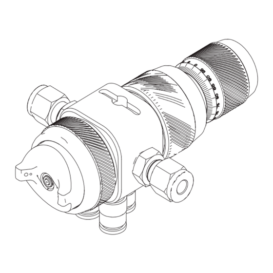
AirPro
Spray Gun
Conventional, HVLP, HiTEch, and LVMP automatic guns for small component finishing
applications. For professional use only.
100 psi (0.7 MPa, 7 bar) Maximum Working Fluid Pressure
100 psi (0.7 MPa, 7 bar) Maximum Working Air Pressure
Important Safety Instructions
Read all warnings and instructions in this
manual. Save these instructions.
See page 3 for model information.
Guns with manifold
™
EFX Automatic
TI14428A
Guns without manifold
313869K
EN
TI14427A
II 2 G c IIB T6
Advertisement
Table of Contents

Related Manuals for Graco AirPro EFX


Summary of Contents for Graco AirPro EFX
- Page 1 Instructions/Parts ™ AirPro EFX Automatic 313869K Spray Gun Conventional, HVLP, HiTEch, and LVMP automatic guns for small component finishing applications. For professional use only. 100 psi (0.7 MPa, 7 bar) Maximum Working Fluid Pressure 100 psi (0.7 MPa, 7 bar) Maximum Working Air Pressure Important Safety Instructions Read all warnings and instructions in this manual.
-
Page 2: Table Of Contents
Position Air Cap ......18 Graco Information ......40 Adjust Spray Pattern . -
Page 3: Models
Models Models Models with Manifold** Models without Manifold Orifice Size Spray Type in. (mm) Gun Part No. Series Gun Part No. Series Conventional 0.028 (0.7) 24B857 24B877 Conventional 0.035 (0.9) 24B858 24B878 Conventional 0.039 (1.0) 24M390* 24M392* Conventional 0.043 (1.1) 24B859 24B879 Conventional... -
Page 4: Warnings
Warnings Warnings The following warnings are for the setup, use, grounding, maintenance, and repair of this equip- ment. The exclamation point symbol alerts you to a general warning and the hazard symbols refer to procedure-specific risks. When these symbols appear in the body of this manual or on warning labels, refer back to these Warnings. - Page 5 Warnings WARNING EQUIPMENT MISUSE HAZARD Misuse can cause death or serious injury. Do not operate the unit when fatigued or under the influence of drugs or alcohol. • Do not exceed the maximum working pressure or temperature rating of the lowest •...
- Page 6 Warnings WARNING TOXIC FLUID OR FUMES HAZARD Toxic fluids or fumes can cause serious injury or death if splashed in the eyes or on skin, inhaled, or swallowed. Read MSDSs to know the specific hazards of the fluids you are using. •...
- Page 7 Warnings 313869K...
-
Page 8: Selection Charts
0.039 light-medium 0.7-6.8 20-200 addition, the LVMP air cap consumes much 0.043 light-medium 0.8-8.5 25-250 less air than the HVLP air cap. Graco LVMP 0.051 medium 1.2-11.8 35-350 guns have no restrictions on air cap pressures. 0.059 medium 1.5-15.2 45-450... -
Page 9: Models With Manifolds
Selection Charts Models With Manifolds Includes: Orifice Size Construction Needle/ Air Cap Construction Fluid of Fluid Assembly Nozzle Kit with Pin of Needle Tip/ Adjustment Fitting Part No. Type Part No. Part No. Nozzle Exit Knob Conven- 24C182 24B857 tional 24D177 0.028 Stainless Steel... -
Page 10: Models Without Manifolds
Selection Charts Models Without Manifolds Includes: Orifice Size Construction Needle/ Air Cap Construction Fluid of Fluid Assembly Nozzle Kit with Pin of Needle Tip/ Adjustment Fitting Part No. Type Part No. Part No. Nozzle Exit Knob Conven- 24C182 24B877 tional 24D177 0.028 Stainless Steel... -
Page 11: Air Caps
Selection Charts Air Caps Nozzle Orifice Recommended Gun/Manifold Air Cap Inlet Pressure Part No. Type psi (MPa, bar) Air Cap Color 24C182 Conventional 0.028-0.059 0.7-1.5 43 (0.3, 3.0) Blue-Grey 24C183 HVLP 0.020-0.051 0.5-1.3 15 (0.1, 1.0)* Pewter 24D703 HiTEch 0.028-0.039 0.7-1.0 29 (0.2, 2.0) Black 24D704... -
Page 12: Installation
Installation Installation This spray gun can spray most coatings or fin- Configure Gun and Manifold ishes currently being used for small compo- Guns with Manifold nent plastic, wood and metal finishing applications, while easily operating from paint See F . 1. The gun is shipped with a fluid plug delivery systems, such as pressure pots or (25). -
Page 13: Ground System
Installation Guns without Manifold Pump/Fluid Supply The gun is shipped ready for use in a circulat- Ground the pump by connecting a ground wire ing system, with a fitting installed in each fluid and clamp between the fluid supply and a true port. -
Page 14: Mount Gun
Installation Mount Gun Reciprocating Arm Rod Mount To mount the gun on a reciprocating arm rod [0.75 in. (19 mm) diameter maximum], insert the bar (A) through the hole in the manifold as shown in F . 3. NOTE: Use the 1/8 in. alignment slot (P) to assist in orienting the gun. -
Page 15: Setup
Setup Setup Connect Air Line 1. The gun cylinder, fan, and atomization air must be supplied and regulated separately. NOTE: To regulate air remotely, use solenoids (see F . 6 and F . 7). If your regulated air source does not •... - Page 16 Setup Air regulator ATOMIZING AIR 2-way solenoid valve CYLINDER AIR 3-way solenoid valve FAN AIR TI14444A 2-way solenoid valve . 6: Remote Air Regulation using Solenoid (Guns with Manifold) FAN AIR 2-way solenoid valve CYLINDER AIR 3-way solenoid valve ATOMIZING AIR TI14445A 2-way solenoid valve...
-
Page 17: Connect Fluid Hose
Setup Connect Fluid Hose In a non-circulating system, remove the gun fluid outlet fitting (T) and plug the outlet NOTE: port with the pipe plug (33) supplied for guns without manifold. Guns with manifold Before connecting the fluid line, blow it •... -
Page 18: Flush Spray Gun
Setup Flush Spray Gun Adjust Spray Pattern Do not exceed 100 psi (0.7 MPa, 7 bar) Before running any paint through the spray maximum fluid and air pressure. Higher gun: pressures can cause parts to rupture and result in serious injury. 1. - Page 19 Setup NOTE: HVLP Gun Limits HVLP Guns: local laws may limit the maximum pressure to 10 psi (70 kPa, 0.7 bar) at the air cap for compliance. See the table on page 11 for maximum HVLP manifold inlet pressures. To measure pressure at the air cap, use the appropriate HVLP Pressure Verification Kit.
-
Page 20: Operation
Operation Operation Pressure Relief Procedure To achieve best results when applying fluid: Keep gun perpendicular and 6 to 8 in. • (150 to 200 mm) from object being sprayed. 1. Turn off all bleed type air valves and all Use smooth, parallel strokes across sur- •... -
Page 21: Daily Gun Care
Operation Daily Gun Care NOTICE Methylene chloride with formic or propionic acid is not recommended as a flushing or cleaning solvent with this gun as it will damage aluminum and nylon components. NOTICE Solvent left in gun air passages could result in a poor quality paint finish. Do not use any cleaning method which may allow solvent into the gun air passages. -
Page 22: General System Maintenance
Operation General System Maintenance 9. Dip the end of a soft-bristle brush into a compatible solvent. Do not continuously Follow the Pressure Relief Procedure, • soak the brush's bristles with solvent and page 20. do not use a wire brush. Clean the fluid and air line filters daily. - Page 23 Operation 313869K...
-
Page 24: Troubleshooting
Troubleshooting Troubleshooting Problem Cause Solution Spray Pattern Normal pattern. No action necessary. Right Spray Pattern Dirty or damaged air cap or Rotate air cap (5) 180°. fluid nozzle. If pattern follows air cap, prob- lem is in air cap. Clean and inspect. - Page 25 Troubleshooting Problem Cause Solution Gun spitting. Air getting into paint stream. Check if fluid source is empty and fill. Tighten fluid nozzle (4). Check fluid nozzle o-ring (3) for damage. Check fluid nozzle (4) for dam- age. Will not spray. Fluid control valve (11) turned Adjust fluid control valve (11) too far clockwise.
-
Page 26: Service
Service Service screws (16) and remove the gun from the manifold. b. Without Manifold: Disconnect the air NOTE: Numbers in parenthesis in the text and fluid hoses. Remove the gun from refer to the reference numbers in the figures the mounting arm. and in the parts list. -
Page 27: Reassembly
Service 6. Use a 1/16 hex wrench to loosen the fluid needle set screw (7a). Remove the needle (6) from the piston (7). 7. Check the fluid needle (6) for damage or excessive wear. Replace the needle if nec- essary. ti14944a Torque to 4.5 to 5.5 in-lb (0.5 to 0.6 N•m). -
Page 28: Parts
Parts Parts Guns with Manifold Ultra-precision knob Indexing knob Lock ring and cap ti14447a ti14945a Guns without Manifold ti14448a 313869K... - Page 29 Parts Parts in Common Additional Parts for Models with Manifold Ref. Part Description Qty. ----- BODY Ref. Part Description 24C205 FLUID PACKING ASSEMBLY 24C215 MANIFOLD, gun (includes Parts 119348 O-RING (included with Part 4) 13, 14, 15, 19, and 20) See Table NOZZLE, fluid (includes Part 3) 106456†...
-
Page 30: Repair Kits
Repair Kits Repair Kits Gun Part Number Item 6 Item 5 Nozzle Needle/Nozzle Item 4 Needle Air Cap Orifice Nozzle Assembly (Includes seals With Without Size (Includes (includes (includes and alignment Spray Type Manifold Manifold in. (mm) Items 4 and 6) o-ring) tip) pin) -
Page 31: Accessories
Accessories Accessories Kit 24C216, Fittings (1/4 inch) Part Description 120388 FITTING, tube, air line, 1/8 npt x 1/4 T 111157 FITTING, tube, fluid line, 1/8 npt x 1/4 T Kit 24D143, Robot Adapter Kit Fanuc Paint Mate 200 Compatible with and without manifold. Kit 24D008, Inlet Air Needle Valve Includes needle valve and 6mm tube fittings. - Page 32 Accessories 313869K...
-
Page 33: Dimensions
Dimensions Dimensions Guns with Manifold 1.6 in. 4.9 in. (124.5 mm) with Ultra-Precision knob (40.7 mm) 4.1 in. (104.1 mm) with indexing knob 3.5 in. (88.9 mm) with lock ring and cap 1.3 in. 2.6 in. (33.0 mm) (66.1 mm) 0.75 in. -
Page 34: Mounting Hole Layouts
Mounting Hole Layouts Mounting Hole Layouts Guns with Manifold 0.95 in (24.1 mm) 1.27 in (32.3 mm) ti14700a 0.34 in. (8.6 mm) thru 1.4 in (35.6 mm) 0.13 in. (3.3 mm) slot 3 x M8 x 1.25 0.43 in. (10.9 mm) 0.86 in. - Page 35 Mounting Hole Layouts Guns without Manifold 1.76 in. (44.7 mm) M8 x 1.25 T 0.35 in. (8.9 mm) deep 0.95 in. (24.1 mm) 0.13 slot (3.3 mm) ti14701a . 23 313869K...
-
Page 36: Technical Data
Technical Data Technical Data Maximum working fluid pressure 100 psi (0.7 MPa, 7 bar) Maximum working air pressure 100 psi (0.7 MPa, 7 bar) Maximum HVLP Inbound Air Pressure See chart on page 11. Maximum Working Fluid Temperature 120° F (49° C) Minimum Air Cylinder Actuation Pressure 50 psi (0.34 MPa, 3.4 bar) Weight... - Page 37 Technical Data Triggering Speed These values apply to a new gun with a 12 ft. (3.6 m), 1/4 in. (6.3 mm) OD cylinder air line and a 0.043 in. nozzle. These values will vary slightly with use and with variations in equipment. Cylinder Air msec to fully msec to fully...
-
Page 38: Air Flow
Air Flow Air Flow See the chart to determine air consumption. Add the air consumption values shown for the atom- izing air and fan air to get the total air consumption. For example, air cap 24C182 with 35 psi inlet pressure uses 3.9 scfm atomizing air and 5.4 scfm fan air for a total of 9.3 scfm air consumption. -
Page 39: Spray Pattern Test Report
Air Flow Spray Pattern Test Report Every AirPro EFX gun must pass a spray pattern test. The test report is printed and shipped in the box with the gun. A sample is reproduced here, with explanatory notes. AirPro EFX Spray Pattern Test Report Use this number for reference in communications with Graco. -
Page 40: Graco Standard Warranty
With the exception of any special, extended, or limited warranty published by Graco, Graco will, for a period of twelve months from the date of sale, repair or replace any part of the equipment determined by Graco to be defective.
Need help?
Do you have a question about the AirPro EFX and is the answer not in the manual?
Questions and answers