Table of Contents
Advertisement
VIESMANN
Technical guide
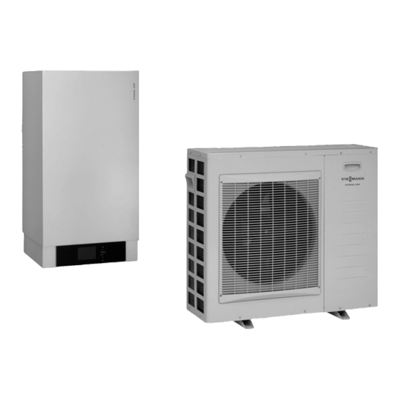
VITOCAL 200-S
Type AWS
Heat pump with electric drive in split design with external and
internal unit.
For central heating and DHW heating in heating systems.
Internal unit with heat pump control unit Vitotronic 200, cir-
■
culation pump for the heating circuit, 3-way diverter valve,
expansion vessel and safety assembly.
Weatherproof external unit with evaporator, compressor,
■
electronic expansion valve and fan.
Permissible operating pressure: Heating water 3 bar
5727 210 GB
9/2010
VITOCAL 200-S
Air/water heat pump, split version
VITOCAL 200-S
Type AWS-AC
Equipment as per AWS type but with an additional cooling
function via the heating circuit and an integral instantaneous
heating water heater.
3.0 to 10.6 kW
Advertisement
Table of Contents

Subscribe to Our Youtube Channel
Related Manuals for Viessmann VITOCAL 200-S AWS


Summary of Contents for Viessmann VITOCAL 200-S AWS
- Page 1 VIESMANN VITOCAL 200-S Air/water heat pump, split version 3.0 to 10.6 kW Technical guide VITOCAL 200-S VITOCAL 200-S Type AWS Type AWS-AC Heat pump with electric drive in split design with external and Equipment as per AWS type but with an additional cooling internal unit.
-
Page 2: Table Of Contents
Index Index Product information 1. 1 Product description ..................... ■ Benefits ........................■ Delivered condition ....................1. 2 Specification ....................... ■ Specification ......................■ Dimensions ......................■ Output diagrams type AWS/AWS-AC 104 .............. 13 ■ Output diagrams type AWS/AWS-AC 107 .............. 14 ■... - Page 3 Index (cont.) Heat pump control unit 5. 1 Vitotronic 200, type WO1A ..................54 ■ Structure and functions ................... 54 ■ Time switch ......................55 ■ Setting the operating programs ................55 ■ Frost protection function ..................56 ■ Heating and cooling curve settings (slope and level) ..........56 ■...
-
Page 4: Product Information 1. 1 Product Description
Product information 1.1 Product description Benefits Internal unit A Expansion vessel B Condenser C 3-way diverter valve heating/DHW D Heating circuit pump E Vitotronic 200, type WO1A ■ Variable output control with DC inverter technology. ■ No risk of frost in the connection lines between the external and ■... -
Page 5: Delivered Condition
Product information (cont.) Delivered condition Type AWS Type AWS-AC Standard delivery: Standard delivery: ■ Complete heat pump with electric drive in split design comprising an ■ Equipment level as for type AWS. external and internal unit. ■ Instantaneous heating water heater integrated into internal unit. ■... -
Page 6: Specification
Product information (cont.) 1.2 Specification Specification Vitocal 200-S Type AWS/AWS-AC Heating output data at 100 % to EN 14511 (A2/W35 °C, spread 5 K) Rated heating output 10.6 Compressor frequency Fan speed Power consumption 0.91 1.73 2.20 3.25 Performance factor ε (COP) in heating 3.30 3.24 3.50... - Page 7 Product information (cont.) Type AWS/AWS-AC Electrical values Internal unit Heat pump control unit/PCB – Rated voltage control unit/PCB 1/N/PE 230 V/50 Hz – Fuse protection, power supply 1xB16A – Fuse, internal 6.3A (slow) / 250 V Instantaneous heating water heater (phase asymmetrical) Integral for type AWS-AC –...
-
Page 8: Dimensions
Product information (cont.) Type AWS/AWS-AC Weighted total sound power level (external unit) Test with reference to DIN EN 12102/ DIN EN ISO 9614-2 under the following conditions: Inlet temperature 7 °C ±3 K, flow temperature 35 °C ±5 K at rated heating output dB(A) Dimensions Internal unit... - Page 9 Product information (cont.) 400 V~ <42 V >42 V 230 V~ Symbol Explanation Connection Refrigerant lines from/to the external unit: – Hot gas line – 4 kW: 7 12 mm – 7 kW: 7 16 mm –10 kW: 7 16 mm –13 kW: 7 16 mm –...
- Page 10 Product information (cont.) External unit Type AWS/AWS-AC 104 VIESMANN VITOCAL 200-S...
- Page 11 Product information (cont.) Type AWS/AWS-AC 107 1040 VIESMANN VITOCAL 200-S...
- Page 12 Product information (cont.) Type AWS/AWS-AC 110 and 113 VIESMANN VITOCAL 200-S...
-
Page 13: Output Diagrams Type Aws/Aws-Ac 104
Product information (cont.) Output diagrams type AWS/AWS-AC 104 35°C 45°C 55°C 55°C 45°C 35°C Air intake temperature in °C 18 °C 18 °C 7°C 7 °C 18 °C 7°C Air intake temperature in °C Air intake temperature in °C Curves subject to the flow temperature: A Heating output at flow temperatures of 35 °C, 45 °C, 55 °C 35 °C B Electrical power consumption for heating at flow temperatures of... -
Page 14: Output Diagrams Type Aws/Aws-Ac 107
Product information (cont.) Cooling capacity data (type AWS-AC only) Operating point °C °C Cooling capacity Power consumption 1.07 1.11 1.13 1.14 1.13 0.96 1.00 1.04 1.05 1.08 Performance factor EER 4.94 4.40 4.20 3.95 3.72 3.54 3.30 3.10 2.95 2.96 Output diagrams type AWS/AWS-AC 107 35 °C 45 °C... -
Page 15: Output Diagrams Type Aws/Aws-Ac 110
Product information (cont.) Curves subject to the flow temperature: C Cooling capacity at flow temperatures of 18 °C, 7 °C, type AWS- A Heating output at flow temperatures of 35 °C, 45 °C, 55 °C AC only B Electrical power consumption for heating at flow temperatures of D Electrical power consumption for cooling at flow temperatures of 35 °C, 45 °C, 55 °C 18 °C, 7 °C... - Page 16 Product information (cont.) 18 °C 18 °C 7 °C 7 °C Air intake temperature in °C 18 °C 7 °C Curves subject to the flow temperature: A Heating output at flow temperatures of 35 °C, 45 °C, 55 °C B Electrical power consumption for heating at flow temperatures of 35 °C, 45 °C, 55 °C C Cooling capacity at flow temperatures of 18 °C, 7 °C, type AWS- AC only...
-
Page 17: Output Diagrams Type Aws/Aws-Ac 113
Product information (cont.) Output diagrams type AWS/AWS-AC 113 35°C 45 °C 55°C 55°C 45 °C 35°C Air intake temperature in °C 35°C 45°C 18 °C 55°C 7 °C -15 -10 -5 10 15 20 25 30 Air intake temperature in °C 18 °C 7 °C 18 °C... -
Page 18: Output Correction Factor
Product information (cont.) C Cooling capacity at flow temperatures of 18 °C, 7 °C, type AWS- Note AC only The COP data in the tables and diagrams was calculated with refer- D Electrical power consumption for cooling at flow temperatures of ence to DIN EN 14511. -
Page 19: Residual Head Of The Integral Circulation Pump
Product information (cont.) Cooling (type AWS-AC) 1.00 0.96 0.92 0.88 0.84 0.80 0.76 0.72 0.68 0.64 0.60 Line length in m A A35/W18 B A35/W7 Example: Corrected output: ■ Type AWS-AC 107 ■ Rated heating output relative to A2/W35: ■ Length of refrigerant line: 10 m 5.6 kW x 0.98 = 5.49 kW ■... -
Page 20: Dhw Cylinder 2. 1 Vitocell 100-V, Type Cvw
DHW cylinder 2.1 Vitocell 100-V, type CVW See information on the design of the DHW cylinder from page 51. For DHW heating in conjunction with heat pumps up to 16 kW and ■ Solar flow temperature up to 140 °C solar collectors;... - Page 21 DHW cylinder (cont.) Cylinder capacity Connections Heating water flow and return 1¼ Cold water, hot water 1¼ Solar internal indirect coil set [indirect coils] ¾ DHW circulation Immersion heater 1½ Information regarding continuous output When designing the system for the continuous output as stated or cal- culated, allow for the corresponding circulation pump.
- Page 22 DHW cylinder (cont.) Pressure drop 1000 DHW throughput in l/h Pressure drop on the DHW side Heating water throughput in litres/h Pressure drop on the heating water side VIESMANN VITOCAL 200-S...
-
Page 23: Vitocell 100 V, Type Cva
DHW cylinder (cont.) 2.2 Vitocell 100 V, type CVA See information on the design of the DHW cylinder from page 51. For DHW heating in conjunction with boilers and district heating sys- ■ Operating pressure on the heating water side up to 25 bar tems, as option with electric heater as accessory for DHW cylinders ■... - Page 24 DHW cylinder (cont.) 160 and 200 litre capacity BÖ HV/SPR KW/E BÖ Inspection and cleaning aperture SPR Cylinder temperature sensor of the cylinder temperature control Drain or the control thermostat Heating water return Protective magnesium anode Heating water flow WW DHW Cold water DHW circulation Capacity...
- Page 25 DHW cylinder (cont.) Capacity Length (7) Width Height 1746 1600 1115 7 100 500 litre capacity HV/SPR BÖ KW/E BÖ Inspection and cleaning aperture SPR Cylinder temperature sensor of the cylinder temperature control Drain or the control thermostat Heating water return Protective magnesium anode Heating water flow WW DHW...
- Page 26 DHW cylinder (cont.) 750 and 1000 litre capacity HV/SPR BÖ KW/E BÖ Inspection and cleaning aperture SPR Cylinder temperature sensor of the cylinder temperature control Drain or the control thermostat Heating water return Protective magnesium anode Heating water flow WW DHW Cold water DHW circulation Capacity...
- Page 27 DHW cylinder (cont.) Peak output (during 10 minutes) Relative to the performance factor N DHW heating from 10 to 45 °C. Capacity 1000 Peak output (l/10 min) at a heating water flow temper- ature of 90 °C 80 °C 70 °C Max.
- Page 28 DHW cylinder (cont.) Pressure drop C Capacity 500 l D Capacity 750 l E Capacity 1000 l DHW throughput in l/h Heating water throughput in litres/h Pressure drop on the DHW side of one cylinder cell. A Cylinder capacity 160 and 200 l B Capacity 300 l Pressure drop on the heating water side C Capacity 500 l...
- Page 29 DHW cylinder (cont.) See information on the design of the DHW cylinder from page 51. For DHW heating in conjunction with boilers and solar collectors for ■ Solar flow temperature up to 160 °C dual-mode operation. ■ Operating pressure on the heating water side up to 10 bar ■...
- Page 30 DHW cylinder (cont.) 300 litre capacity HV/SPR1 HVs/SPR2 SPR1/ SPR2 KW/E Drain SPR1 Cylinder temperature control sensor Immersion heater SPR2 Temperature sensors/thermometer Heating water return Thermometer (accessory) Heating water return, solar thermal system Protective magnesium anode Heating water flow DHW circulation Heating water flow, solar thermal system Cold water Inspection and cleaning aperture with flange cover (also suit-...
- Page 31 DHW cylinder (cont.) 400 and 500 litre capacity HV/SPR1 Ø 650 HVs/SPR2 SPR1/ SPR2 KW/E Drain SPR1 Cylinder temperature control sensor Immersion heater SPR2 Temperature sensors/thermometer Heating water return Thermometer (accessory) Heating water return, solar thermal system Protective magnesium anode Heating water flow DHW circulation Heating water flow, solar thermal system...
- Page 32 DHW cylinder (cont.) Cylinder temperature sensor for solar operation Arrangement of cylinder temperature sensor in the heating water return HR A Cylinder temperature sensor (standard delivery of solar control unit) B Threaded elbow fitting with sensor well (standard delivery) Performance factor N To DIN 4708.
- Page 33 DHW cylinder (cont.) Information regarding max. draw-off rate For multi-cylinder banks, the performance factor N , the peak output and the max. draw off rate cannot be determined by multiplying the performance factor N , the peak output and the max. draw off rate of the individual cylinders by the number of cylinders.
- Page 34 DHW cylinder (cont.) Pressure drop C Cylinder capacity 500 l (lower indirect coil) D Cylinder capacity 400 l (lower indirect coil) 1000 DHW throughput in litres/h Pressure drop on the DHW side A Cylinder capacity 300 l B Cylinder capacity 400 and 500 l Heating water throughput in litres/h Pressure drop on the heating water side A Cylinder capacity 300 l (upper indirect coil)
-
Page 35: Installation Accessories 3. 1 Heating Circuit (Secondary Circuit)
Installation accessories 3.1 Heating circuit (secondary circuit) Instantaneous heating water heater (3/6/9 kW) Part no. Z008 988 For installation into the Vitocal, can be plugged in electrically and hydraulically ■ High limit safety cut-out ■ Control module ■ Thermal insulation Note Type AWS-AC has an integral instantaneous heating water heater. -
Page 36: Cooling
Installation accessories (cont.) 3.2 Cooling Fan convectors Vitoclima 200-C ■ With three-way control valve ■ With 4-pipe heat exchanger for heating and cooling ■ For wall mounting Fan convector Vitoclima 200-C Type V202H V203H V206H V209H Z004 926 Z004 927 Z004 928 Z004 929 Plinth for floor mounting... -
Page 37: Room Temperature Sensor For Separate Cooling Circuit
Installation accessories (cont.) Type Dimensions in mm V202H V203H 1138 1132 V206H 1508 1502 V209H 1508 1502 A Air outlet B Top C 4 fixing holes 7 8 mm D Bottom E Floor F Air inlet Type Dimensions in mm V202H V203H V206H... -
Page 38: Contact Temperature Sensor
IP rating IP 32 to EN 60529; ensure through appropriate design and installation Sensor type Viessmann Ni500 Permissible ambient temperature – during operation 0 to +120 °C – during storage and transport -20 to +70 °C 3-way diverter valve (R 1) Part no. -
Page 39: Impressed Current Anode
Installation accessories (cont.) Note The immersion heaters part no. Z004 955 and 7147 972 must not be used for operation at 230 V~. In this case, commercially available immersion heaters must be used for operation with Vitocell 100-V, type CVW. Impressed current anode Part no. -
Page 40: Installation Of The External Unit
Installation accessories (cont.) 3.5 Installation of the external unit Floor bracket for external unit ■ Part no. 7249 299 For installation on a flat roof or level ground surface. Floor bracket 2 pieces, length 450 mm ■ Part no. 7249 300 Cover for floor bracket 4 pce Bracket set for mounting the external unit on a wall... - Page 41 Design information (cont.) ■ To drain the condensate via a sewer system, install a siphon with a ■ When installing the unit where it is exposed to wind, ensure on site hydraulic seal of at least 60 mm in an area free from the risk of frost that the wind cannot influence the fan area.
- Page 42 Design information (cont.) Installation on floor spacers A Mounting supports (rubber cushion) B Floor spacers C Foundation strips D Heated condensate line (7 16 mm) E Minimum clearance: Snow cover + 100 mm F Booster heater for condensate pan G Pathway, patio H Ground K Drain pipe (at least DN 50) L Stench trap (siphon) in an area free from the risk of frost...
-
Page 43: Installing The Internal Unit
Design information (cont.) Installing the internal unit Installation room requirements Note ■ Dry and protected against frost. Ensure ambient temperatures of 0 If several heat pumps are to be installed in one room, add the minimum to 35 ºC, humidity max. 20 g/kg dry air. room volumes of the individual appliances together. -
Page 44: Electrical Connections
Design information (cont.) Internal and external unit at the same level Internal and external unit at different levels, example: internal unit above external unit Internal unit External unit Liquid gas line Hot gas line Flow direction for heating mode Flow direction for cooling mode Internal unit External unit Liquid gas line... - Page 45 Design information (cont.) Wiring diagram A Outside temperature sensor, sensor lead (2 x 0.75 mm G Power cable, instantaneous heating water heater (see table) B External unit H Power cable, heat pump control unit (see table) C Compressor power cable, 230 V~ (see table) K Electricity meter/mains D BUS connecting lead L Cylinder primary pump (only in conjunction with primary store...
-
Page 46: Hydraulic Connections
Design information (cont.) 4.3 Hydraulic connections Symbol Explanation Connection Hot gas line – 4 kW: 7 12 mm – 7 kW: 7 16 mm –10 kW: 7 16 mm –13 kW: 7 16 mm Liquid gas line – 4 kW: 7 6 mm –... -
Page 47: Noise Development
Design information (cont.) 4.4 Noise development Note c [dB(A)] The requirements specified in TA Lärm [Germany] must always be observed. b [dB(A)] Sound pressure levels a, b, c in dB(A), measured at different dis- tances (semi-free measurement, Q=2) at a fan rating of 80 to 100 % External unit type AWS/AWS-AC a in dB(A) -
Page 48: System Versions
Design information (cont.) In this connection, please observe the following: – Avoid surroundings with hard reflecting floors, such as concrete or plaster, as the sound pressure level can be increased through reflections. Surroundings that are covered with vegetation, e.g. lawn, can noticeably reduce the perceived sound pressure level. –... -
Page 49: Supplement For Dhw Heating
Design information (cont.) Supplement for DHW heating For general house building, a max. DHW consumption of approx. 50 litre per person per day at approx. 45 ºC is assumed. ■ This represents an additional heat load of approx. 0.25 kW per per- son given a heat-up time of 8 h. -
Page 50: Sizing The Heating Water Buffer Cylinder
Design information (cont.) Example Curves subject to the flow temperature: 35 °C A Heating output at flow temperatures of 35 °C, 45 °C, 55 °C B Electrical power consumption for heating at flow temperatures of 35 °C, 45 °C, 55 °C 45 °C C Heat load D Dual mode point for a radiator system... -
Page 51: Dhw Connection
Design information (cont.) 4.8 DHW connection Example with Vitocell 100-V, type CVW Connection to DIN 1988. L M NF K F P K S O A DHW L Flow regulating valve B DHW circulation line (installation recommended) M Pressure gauge connector C DHW circulation pump N Non-return valve D Spring-loaded check valve... -
Page 52: System Examples
Quan- Part no. tity Cylinder temperature sensor 7170 965 Spring-loaded check valve on-site EHE immersion heater See Viessmann pricelist DHW circulation pump See Vitoset pricelist DHW cylinder See Viessmann pricelist Cannot be achieved at low outside temperatures. VIESMANN VITOCAL 200-S... -
Page 53: Cooling (Type Aws-Ac Only)
Design information (cont.) 4.10 Cooling (type AWS-AC only) In cooling operation, the Vitocal 200-S operates in reverse mode, i.e. Note the processes of the heat pump circuit run in reverse order. For cooling mode in the following cases, a room temperature sensor Cooling is possible either through an underfloor heating circuit or via must be installed and enabled: a separate cooling circuit, e.g. -
Page 54: Heat Pump Control Unit 5. 1 Vitotronic 200, Type Wo1A
Design information (cont.) Test conditions At 20 °C room temperature, flow temperature 50 °C. ■ Cooling capacity: ■ Sound pressure level At 27 °C room temperature, 48% relative humidity, cooling the cool- Measured at a distance of 2.5 m with a room volume of 200 m ing water from 12 to 7 °C. -
Page 55: Time Switch
Heat pump control unit (cont.) Programming unit ■ Demand-dependent shutdown of the heat pump and pumps for pri- ■ Simple operation: mary and secondary circuits – Plain text display with graphic ability ■ Adjustment of a variable heating and cooling limit –... -
Page 56: Frost Protection Function
Heat pump control unit (cont.) Frost protection only The operating programs can also be switched over externally, e.g. by Vitocom 100. Frost protection function ■ The frost protection function will be started when the outside tem- perature drops below approx. +1 °C. With active frost protection, the heating circuit pump will be switched on and the flow temperature in the secondary circuit will be main- tained at a lower temperature of approx. -
Page 57: Specification Vitotronic 200, Type Wo1A
(cont.) Specification IP rating IP 43 to EN 60529; Ensure through appropri- ate design/installation Sensor type Viessmann Ni500 Permissible ambient temperature during −40 to +70 °C operation, storage and transport Specification Vitotronic 200, type WO1A General Rated voltage 230 V~... -
Page 58: Cylinder Temperature Sensor
IP 32D to EN 60529 ensure through appropriate Components: design/installation ■ Mixer PCB with mixer motor for Viessmann mixer DN 20 to 50 and Protection class R ½ to 1¼ Permissible ambient temperature ■ Flow temperature sensor (contact temperature sensor), lead length –... -
Page 59: Extension Kit For One Heating Circuit With Mixer For Separate Mixer Motor
Mixer PCB Secured with a tie. Specification IP rating IP 32D to EN 60529 ensure through appropriate design/installation Sensor type Viessmann NTC 10 kΩ at Specification 25 °C Rated voltage 230 V~ Permissible ambient temperature Rated frequency 50 Hz – during operation 0 to +120 °C... -
Page 60: Contact Temperature Sensor As System Flow Temperature Sensor
– during storage and transport -20 to +70 °C Mixer motor Part no. 7450 657 Specification The mixer motor is mounted directly onto the Viessmann mixer DN 20 Rated voltage 230 V~ to 50 and R ½" to 1¼". Rated frequency 50 Hz With system plug. -
Page 61: Km Bus Distributor
Heat pump control unit (cont.) ■ Party and economy mode can be enabled via keys. ■ Only for heating circuit with mixer: Room temperature sensor for room temperature hook-up Note For room temperature hook-up, the Vitotrol 200A must be installed in the living space (lead room). -
Page 62: Mounting Base For Programming Unit
■ With contract SIM card for the operation of the Vitocom 100 via mobile phone Part no. Z004615 Note For further information regarding the conditions of contract, see the Viessmann pricelist. Specification Rated voltage 230 V ~ Functions: Rated frequency 50 Hz ■... -
Page 63: Keyword Index
Keyword index 3-way diverter valve.................38 Heating circuit pump................35 Heating curve...................55 ■ Level.....................56 Anti-seizing pump protection............55 ■ Slope.....................56 Application procedure (details)............40 Heating limit..................55 Auxiliary function Heating output..................48 ■ DHW heating.................55 Heating program................55 Heating water buffer cylinder............50 Heat load..................48 Booster heater..................38 Heat pump control unit..............54 ■... - Page 64 Structure-borne noise...............47 Supplement for DHW heating............49 Supplement for setback mode............49 Swimming pool water heating............55 System versions................48 Subject to technical modifications. Viessmann Werke GmbH&Co KG Viessmann Limited D-35107 Allendorf Hortonwood 30, Telford Telephone: +49 6452 70-0 Shropshire, TF1 7YP, GB Fax: +49 6452 70-2780 Telephone: +44 1952 675000 www.viessmann.com...
Need help?
Do you have a question about the VITOCAL 200-S AWS and is the answer not in the manual?
Questions and answers