
Subscribe to Our Youtube Channel
Related Manuals for Nav TV NTV-KIT585


Summary of Contents for Nav TV NTV-KIT585
- Page 1 3950 NW 120 Ave, Coral Springs, FL 33065 TEL 561-955-9770 FAX 561-955-9760 NNG-Ford V2 Navigation interface for FORD vehicles equipped with 8.4” MyTouch NTV-KIT585 NTV-DOC223...
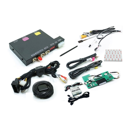
- Page 2 NTV-DOC223 NTV-KIT558: FORD V1 SoftTouch Navigation System NTV-KIT585: FORD V2 2011-2013 Ford Escape Installation Instructions Compatibility INSTALLATION PERFORMED ON ESCAPE FOR REFERENCE ONLY. Parts Identification Page 1 Vehicle Preparation Page 2 n i t Installation Page 3 Parts Identification Item Qty.
- Page 3 NTV-DOC223 STOP – Install At Your Own Risk YOU MUST READ THESE WARNINGS AND NOTICE BEFORE PRODUCT HANDLING AND INSTALLATION! PRODUCT AND VEHICLE APPLICATION WARRANTY DISCLAIMER WARNING ! The Navigation Electronic Components are sensitive to Electro- Static Discharge (ESD). DO NOT HANDLE THE NAVIGATION ELECTRONIC COMPONENTS WITHOUT PROPER ESD GROUNDING DURING INSTALLATION.
- Page 4 NTV-DOC223 WARNING To avoid dangerous distractions that may lead to an accident, the driver should never operate the system while the vehicle is in motion. Before installing this product, the seller should inform the end-user of proper use and compliance with the proper instructions and all state and federal laws.
- Page 5 NTV-DOC223 Installation Using even pressure, gently remove the upper Remove the two screws from the upper radio mounts. dashboard trim sliding it out of the way just enough to access the upper radio mounting screws. Remove the dashboard trim surrounding the touch Tilt the dashboard trim forward and detach the air screen unit using an automotive trim tool.
- Page 6 NTV-DOC223 Remove the four screws securing the touch screen unit Gently turn the touch screen unit towards the driver’s to the dashboard. side of the vehicle to easily access the factory wiring harnesses. Gently remove these harnesses (Note: the large factory Gently lift the touch screen unit from the vehicle’s harness includes a locking retainer clip.) dashboard.
- Page 7 NTV-DOC223 1. To begin, place the LCD assembly face down on a soft surface (ESD mat would be best) so as not to scratch the screen. Remove (4x) Phillips head screws: 2. Separate the two halves of the assembly by pulling straight up after the screws have been removed.
- Page 8 NTV-DOC223 5. Next, remove (2x) Phillips head screws on the top and bottom of the LCD housing: 6. Caref lly separate the metal bracket from the LCD housing, this will expose the touch panel ribbon cable and allow the LCD screen to be separated from the back half of the housing: 7.
- Page 9 NTV-DOC223 9. ay the back metal housing down with the circuit board facing up in the orientation shown, and remove (3x) Phillips head screws: 10. F om the NTX54-Ford kit, gather the sub-board with ribbons attached. Fold the main, bigger ribbon underneath the board like shown below.
- Page 10 NTV-DOC223 12. Place the sub-board in the rear LCD housing like shown. This is how the sub-board will be installed into the LCD housing, with the OEM Ford circuit board beneath the NTX54-Ford circuit board. The harnesses from step 11 will be ran through the center square and connected to their prospective connectors: 13.
- Page 11 NTV-DOC223 14. Replace the factory Ford circuit board. The NTX54-Ford circuit board needs to be palced on top. Connect the wider ribbon that was tucked underneath the board from step 10 and the touch panel ribbon to the factory Ford circuit board like shown below. Use the extended screws provided with the V2 NTX54-Ford kit to secure both PCB’s down to the metal chassis.
- Page 12 NTV-DOC223 Ford LCD 15. F ip the modified LCD housing upside down, and place the LCD panel just above the housing. This will make reconnecting the factory ribbons to the new NTX54-Ford PCB easier: NNG-FORD Ford PCB Page 11...
- Page 13 NTV-DOC223 Remove the protective layer from the adhesive backing Mount the GPS antenna to the top-rear of the vehicle on the GPS speaker and attach it to the interior allowing it to attach using its magnetic base. dashboard frame behind the touch screen. Route the GPS antenna extensions harness to the front Connect the TP-IN and LCD-IN harness to the PINK of the vehicle above the headliner, down the...
- Page 14 NTV-DOC223 Connect the power harness from the vehicle interface Connect the speaker interface harness to the harness to the navigation control module. navigation control module. Find the threaded end of the GPS antenna and connect Connect the vehicle interface harness to the factory it to the navigation control module.
- Page 15 NTV-DOC223 Apply the included VHB tape to the bottom side of the Attach the navigation control module to the dashboard navigation control module. in the open cavity below the touch screen unit. Attach the vehicle interface harness to the backside of Connect the TP-IN and LCD-IN harnesses previously the touch screen unit.
- Page 16 NTV-DOC223 Replace the touch screen unit. Make sure no wires are Mount the supplied membrane switch to the radio pinched in the process. control panel. Replace the dashboard trim pieces. If indoors, start the vehicle and move it outside so that the GPS antenna has a clear view of the sky.
- Page 17 NTV-DOC223 Reassembly 1. Reinstall all trim pieces taking special care to ensure harnesses and wiring connections are properly secured. 2. Make sure no harnesses are bent or pinched by trim pieces. 3. Reconnect all disconnected bulbs and check for function. Installation Tips Confirm proper cable extension connector orientation and always verify proper ends are routed in correct direction.
- Page 18 Ford Audio Integration Supplementary Manual This is a supplementary installation manual for FORD Navigation system with factory speaker integration. Please carefully refer to the main installation instruction for navigation system. WARRANTY DISCLAIMER NOTICE! Radio removal, disassembly, installation of Navigation Electronics, and Radio re-assembly / re-installation is the responsibility of the installer.
- Page 19 Ford Audio Integration Supplementary Manual (cont.) Components for audio integration: GPS Audio Box Wiring (FD-AUDSPK-02) Wiring (AUD-6PIN-01) Main Harness (same harness used in main install) Rear-LCD (connected to GPS box from main install) Steps: Connect both FD-AUDSPK-02 and AUD-6PIN-01 to GPS Audio Box Connect white power plug to Main Harness Insert green wire with pin to Main Harness (See figure 1) green wire from...
- Page 20 IGO PRIMO MAP PATH SETTING 1. Press Setup ‐> Navigate Setup 2. Press on the Folder Icon 3. Select the following path in Storage Card ‐> cyb_navi.exe 4. Press HOME button on the top left corner and press NAVIGATION 5. System should able to run into “IGO PRIMO”...
- Page 21 WEAK /NO GPS SIGNAL? Tips to Improve GPS Antenna Signal if vehicle equipped Metallized Windshield* “GPS MONITOR Tools” Exit IGO MAP by press SHUT DOWN BUTTON Console> SETUP GPS MONITOR Locate the Antenna with minimum 5 bars in dark blue or Gray bar (Always suggest mounting the GPS antenna on the roof) Press “!”...
- Page 22 PROPER GPS ANTENNA POSITION if vehicle equipped *Metallized Windshield SUV/Coupe Sedan TRUCK (Shown as Tundra) Alternatively, installer might choose to mount Antenna inside the headliner or inside vehicle using GPS monitor tools (see instruction). However, stay away from the windshield. * Windshields with metal particles can interfere with radio waves, dash-mount satellite radio receivers, and GPS receivers may be affected external transmitters and receivers may be required.
Need help?
Do you have a question about the NTV-KIT585 and is the answer not in the manual?
Questions and answers