Table of Contents
Advertisement
Quick Links
AUTOMATIC WELDING SYSTEMS
For use with the following models:
Safety Depends on You
Lincoln arc welding and cutting
equipment is designed and built
with safety in mind. However,
your overall safety can be
increased by proper installation
... and thoughtful operation on
your part. DO NOT INSTALL,
OPERATE OR REPAIR THIS
EQUIPMENT WITHOUT READ-
ING THIS MANUAL AND THE
SAFETY PRECAUTIONS CON-
TAINED THROUGHOUT. And,
most importantly, think before
you act and be careful.
World's Leader in Welding and Cutting Products
22801 St. Clair Ave. Cleveland, Ohio 44117-1199 U.S.A. Tel. (216) 481-8100
RETURN TO MAIN INDEX
NA-5
NA-5N
NA-5NF
NA-5S
NA-5SF
SERVICE MANUAL
Sales and Service through Subsidiaries and Distributors Worldwide
SVM131-A
Premier Manufacturer of Industrial Motors
July, 1997
Advertisement
Table of Contents
Troubleshooting

Related Manuals for Lincoln Electric NA-5N


Summary of Contents for Lincoln Electric NA-5N
- Page 1 World's Leader in Welding and Cutting Products Sales and Service through Subsidiaries and Distributors Worldwide 22801 St. Clair Ave. Cleveland, Ohio 44117-1199 U.S.A. Tel. (216) 481-8100 RETURN TO MAIN INDEX NA-5 NA-5N NA-5NF NA-5S NA-5SF Premier Manufacturer of Industrial Motors...
-
Page 2: California Proposition 65 Warnings
Miami, Florida 33135 or CSA Standard W117.2-1974. A Free copy of “Arc Welding Safety” booklet E205 is available from the Lincoln Electric Company, 22801 St. Clair Avenue, Cleveland, Ohio 44117-1199. BE SURE THAT ALL INSTALLATION, OPERATION, MAINTENANCE AND REPAIR PROCEDURES ARE PERFORMED ONLY BY QUALIFIED INDIVIDUALS. -
Page 3: Electric Shock Can Kill
ELECTRIC SHOCK can kill. 3.a. The electrode and work (or ground) circuits are electrically “hot” when the welder is on. Do not touch these “hot” parts with your bare skin or wet clothing. Wear dry, hole-free gloves to insulate hands. 3.b. - Page 4 WELDING SPARKS can cause fire or explosion. 6.a. Remove fire hazards from the welding area. If this is not possible, cover them to prevent the welding sparks from starting a fire. Remember that welding sparks and hot materials from welding can easily go through small cracks and openings to adjacent areas.
- Page 5 PRÉCAUTIONS DE SÛRETÉ Pour votre propre protection lire et observer toutes les instructions et les précautions de sûreté specifiques qui parraissent dans ce manuel aussi bien que les précautions de sûreté générales suiv- antes: Sûreté Pour Soudage A L’Arc 1. Protegez-vous contre la secousse électrique: a.
-
Page 6: Table Of Contents
MASTER TABLE OF CONTENTS FOR ALL SECTIONS Safety ........... Installation . - Page 7 NOTES NA-5...
-
Page 8: Electrode Polarity
Section A TABLE OF CONTENTS - INSTALLATION SECTION - Installation ..........Section A Technical Specifications . -
Page 9: Installation
TECHNICAL SPECIFICATIONS – NA-5 NA-5 GEAR RATIO 21:1 57:1 95:1 142:1 MODEL NA-5 Control Box INSTALLATION MINIMUM ELECTRICAL INPUT REQUIREMENTS 115 VAC @ 3 amps 50/60 Hz power REQUIRED WELDING POWER SOURCE DC Constant Voltage WIRE FEED SPEED and GEAR RATIOS FEED SPEED RANGE in./min (m/min) 100 - 2070 (2.54 - 52.6) -
Page 10: Installation
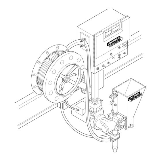
FIGURE A.1 – BASIC CONTROL AND WIRE DRIVE SYSTEM. CONTROL CABLE POWER SOURCE TACHOMETER CABLE 4 FT (1.2 M) CABLE (DRIVE MOTOR TO CONTROL BOX) 4 FT (1.2 M) ELECTRODE CABLES [(TWO 4/0) CONTACT ASSEMBLY TO CONTROL BOX] INSTALLATION CONTROL BOX HEAD MOUNTING PARTS (WITH INSULATION AND HARDWARE) -
Page 11: Mechanical Installation
MECHANICAL INSTALLATION WARNING INTRODUCTION This section covers the basic requirements to install the control box and welding head shown in Figure A.1. This section will give you mounting hole alignments, component mounting clearances, and any special instructions or precautions that must be fol- lowed when installing the control box and mounting head. -
Page 12: Welding Head Installation
To install the control box on a fixture, perform the following steps and refer to Figure A.3. 1. Align the mounting holes on the back and/or bottom of the control box with the holes you put in the fixture according to the measurements provided in Figure A.3. -
Page 13: Electrical Installation
The K338 for the NA-5N, NF, and SF heads is the same as the K335 without the flux hopper lead extension. The NA-5N and NA-5S also include two 4 ft (1.2 m) lengths of electrode cable. -
Page 14: Power Supply To Control Box Connections
The “F” models do not include the 4 ft (1.2 m) lengths of electrode cable as standard. If you are not using a K335 or K338 exten- sion cable for the NA-5NF or NA-5SF, order an appropriate length of the needed elec- trode cable. -
Page 15: Electrode Polarity
ELECTRODE POLARITY Polarity is changed at the power source. The polarity of the NA-5 control circuit is shipped connected for electrode positive. If electrode negative is required, two leads inside the NA-5 control must be reversed. Proceed as follows: 1. Turn off the input power to the NA-5 control box by turning off the welding power source. - Page 16 FIGURE A.8 – CONNECTION OF NA-5 (ALL) TO A DC-600. ALL CODES: TURN OFF INPUT POWER ADJUST THE POWER SOURCE: DC-600: 1. CONNECT ELECTRODE CABLES TO TERMINAL OF DESIRED POLARITY. 2. SET TOGGLE SWITCH TO SAME POLARITY AS THE ELECTRODE CABLE CONNECTION.
- Page 17 A-10 FIGURE A.9 – CONNECTION OF NA-5 (ALL) TO A DC-650 PRO CONTROL CABLE CONNECT TO CABLES FROM NA-5 WIRE CONTACT ASSEMBLY NOTE: ABOVE DIAGRAMS SHOW ELECTRODE CONNECTED POSITIVE. TO CHANGE POLARITY, TURN POWER OFF, REVERSE THE ELECTRODE AND WORK CABLES AT THE POWER SOURCE AND POSITION THE SWITCH ON THE POWER SOURCE TO PROPER POLARITY. REFER TO NA-5 OPERATING MANUAL FOR REQUIRED NA-5 CONTROL BOX POLARITY CONNECTIONS.
- Page 18 A-11 FIGURE A.10 – CONNECTION OF NA-5 (ALL) TO A R3S-400, -600, OR -800 WITH NO LINE VOLTAGE COMPENSATOR (OBSOLETE). NOTE: ABOVE DIAGRAM SHOWS ELECTRODE CONNECTED POSITIVE. TO CHANGE POLARITY, TURN POWER OFF, REVERSE THE ELECTRODE AND WORK CABLES AT THE POWER SOURCE AND POSITION THE SWITCH ON POWER SOURCE TO PROPER POLARITY.
- Page 19 A-12 FIGURE A.11 – CONNECTION OF NA-5 (ALL) TO A SAM-400 MOTOR NOTE: TO CHANGE POLARITY, TURN POWER OFF, AND POSITION THE SWITCH ON POWER SOURCE TO PROPER POLARITY. REFER TO NA-5 OPERATING MANUAL FOR REQUIRED NA-5 CONTROL BOX POLARITY CONNECTIONS. SAM POWER SOURCE SETTINGS TURN POWER SOURCE OFF.
- Page 20 A-13 FIGURE A.12 – CONNECTION OF NA-5 (ALL) TO A SAM-650 ENGINE WELDER. POWER SOURCE "TAP" SAM POWER SOURCE SETTINGS TURN POWER SOURCE OFF. FOR SUB ARC: 1. SET THE ELECTRODE POLARITY SWITCH TO THE POLARITY DESIRED FOR THE PROCESS BEING USED. 2.
- Page 21 A-14 FIGURE A.13 – CONNECTION OF NA-5 TO DC-1000 OR DC-1500. POWER SOURCE THE DIAGRAM SHOWS ELECTRODE CONNECTED POSITIVE. TO CHANGE POLARITY, TURN POWER OFF, REVERSE THE ELECTRODE AND WORK LEADS AT THE POWER SOURCE, POSITION THE POSITIVE-NEGATIVE SWITCH ON THE POWER SOURCE TO CORRESPOND TO THE POLARITY OF THE ELECTRODE CABLE CONNECTION. REFER TO NA-5 OPERATING MANUAL FOR REQUIRED NA-5 CONTROL BOX POLARITY CONNECTIONS.
- Page 22 A-15 FIGURE A.14 – CONNECTION OF NA-5 TO DC-400 OR CV-400. POWER SOURCE N.H. NEGATIVE THE DIAGRAM SHOWS ELECTRODE CONNECTED POSITIVE. TO CHANGE POLARITY, TURN POWER OFF, REVERSE THE ELECTRODE AND WORK LEADS AT THE POWER SOURCE AND POSITION THE SWITCH ON POWER SOURCE (IF EQUIPPED), TO PROPER POLARITY. REFER TO NA-5 OPERATING MANUAL FOR REQUIRED NA-5 CONTROL BOX POLARITY CONNECTIONS.
- Page 23 A-16 A-16 NOTES NA-5...
-
Page 24: Setting Travel Starting And Stopping
Section B TABLE OF CONTENTS - OPERATING INSTRUCTIONS SECTION - Operating Instructions ........Section B Safety Precautions . -
Page 25: Operating Instructions
OPERATING INSTRUCTIONS SAFETY PRECAUTIONS WARNING Observe additional Safety Guidelines detailed in the beginning of this manual. OPERATOR’S INSTRUCTIONS Once the system is properly set up, the operator can make production welds without readjusting the controls using the following simple instructions: 1. -
Page 26: Controls Under The Lockable Security Cover
OPERATING INSTRUCTIONS CONTROLS AND THEIR FUNCTIONS The operator controls for the NA-5 are illustrated in Figure B.1. Refer to the figure and the following explanations of the controls. EXPOSED CONTROLS (WITH LOCKABLE COVER DOWN) 1. CIRCUIT BREAKER. Protects the circuit from severe wire feed motor overloads and short circuits. -
Page 27: Setup Instructions
OPERATING INSTRUCTIONS SETUP INSTRUCTIONS Use the following steps to set up the NA-5 welding system prior to welding: 1. If using a multi-process power source (SAM, DC-400, DC-600, DC-1000, OR DC-1500 type), make con- nections and settings per the power source connection diagram (Figures A.8 to A.14) for the process being... -
Page 28: Starting And Stopping Sequences
OPERATING INSTRUCTIONS 11. Set the travel speed as specified by the procedures. With the wire feeder travel switch set to “Hand Travel”, the travel runs without welding, permitting accurate measurement of travel speed. When using a Lincoln travel carriage, adjust the speed with the rheostat and the direction with the toggle switch on the carriage control panel. -
Page 29: Reconfiguring The Travel Sequences
OPERATING INSTRUCTIONS The starting sequence is as described above except that when the arc strikes, the machine welds at the wire speed and voltage set by the “Start Controls” panel until the time set on the thumbwheel switch elapses. The circuit then automatically switches to the “Welding Controls”... - Page 30 OPERATING INSTRUCTIONS TABLE B.1 – TRAVEL SEQUENCE LEAD AND SWITCH POSITIONS. Travel Starts Travel Stops With “Start” With “Stop” Button Button With Arc Striking With Arc Stopping With Arc Striking With Stop Button With “Start” With End Crater Button Fill Time (With optional procedure module installed in crater receptacle...
- Page 31 OPERATING INSTRUCTIONS Wire Feed Motor Acceleration WARNING The NA-5 has two different speeds of controlled wire feed motor acceleration. As shipped, the unit is connected for fast acceleration which is best for most applications. To change to the slower acceleration, turn off all input power to the NA-5 control box.
-
Page 32: Voltage Control Response
OPERATING INSTRUCTIONS When “Stop” Button is Pressed Feed motor stops and electrode burns back with contactor delay (standard) Feed motor inches up and electrode burns back with contactor delay Feed motor inches up and contactor opens (no burnback) VOLTAGE CONTROL RESPONSE The NA-5 is provided with selectable voltage control response. -
Page 33: Automatic Shutdown
B-10 OPERATING INSTRUCTIONS AUTOMATIC SHUTDOWN If the NA-5 voltage control is unable to supply the “Set” value of the arc voltage while welding, the automatic shutdown circuit will activate. This protection circuit immediately returns the NA-5 control to idle state within a few seconds after the arc voltage discrepancy occurs. -
Page 34: Cold Start Circuitry
B-11 OPERATING INSTRUCTIONS In some cases, it is also possible to hold the “Actual” button pressed while starting the arc. Before the NA-5 shuts down, the actual arc voltage can be read on the digital meter. Comparing this reading to the “Set” reading will tell what change in the range controls of the power source are required so it can supply the desired voltage. -
Page 35: Security Of Weld Procedure Settings
B-12 OPERATING INSTRUCTIONS SECURITY OF WELD PROCEDURE SETTINGS There are two means provided to prevent or limit unauthorized readjustment of the NA-5 voltage and wire feed speed controls once set to the desired procedure. 1. The security panel of the NA-5 can be locked to prevent access to the control knobs. -
Page 36: Listing Of Accessories
Section C - ACCESSORIES SECTION - Accessories ..........Section C General . -
Page 37: Accessories
GENERAL This section contains a listing and short description of the accessories that are TABLE C.1 – NA-5 AUTOMATIC WELDING SYSTEM ACCESSORIES. Product Number K129 K148 K149 K218 K219 K223 K225 K238 K239 K278 K281 K285 K310 K325 K334 K336... -
Page 38: K218 Horizontal Fillet/Lap Attachment
IM305 manual, and can also be ordered as Sec. T2.5.4. K219 FLUX HOPPER KIT This flux hopper, which has an electric flux valve, can be mounted on NA-5N and NA-5NF heads for submerged arc welding. Installation instructions are included with each kit. The operator and maintenance ®... -
Page 39: K225 Submerged Arc Twinarc Kit
K225 SUBMERGED ARC TWINARC KIT The Twinarc kit provides for the feeding of two 5/64, 3/32, or 1/8 in. (1.98, 2.38, or 3.18 mm) solid wires through a single wire feeder. The electrode wire must be the same size. The assembly includes a wire reel, insulated reel mounting bracket, wire straightener, dual wire guides, nozzle, and contact block. -
Page 40: K334 Start And Crater Controls
K334 START AND CRATER CONTROLS Easily installed procedure and timer boards to permit adjustment of wire speed and voltage. Can be installed to function at either the start of the weld or at the end for crater filling. Installation, operating, and maintenance instructions are shipped with each kit and can be ordered as Sec. - Page 41 NOTES NA-5...
-
Page 42: Optional Features
Section D - MAINTENANCE SECTION - Maintenance ..........Section D Control Box . -
Page 43: Circuit Protection
CONTROL BOX GENERAL Inspect the control box every 3 months. If needed, blow dirt out using low pressure air. No further maintenance should be required. CIRCUIT PROTECTION The circuit breaker mounted on the left side of the control box protects the control circuit from short circuit conditions and from severe wire feed overloads. -
Page 44: Wire Drive Gear Box
The 1/8 amp fast-blow fuse, shown in Figure D.3, on a voltage PC board built since 1983, protects the NA-5 circuitry from damage which may result from a ground or case faulted control lead. If the fuse blows, the NA-5 voltage sensing lead circuit will be opened (Refer to Automatic Shutdown in Section B, Operating Procedures) and the Troubleshooting Guide. -
Page 45: Changing Wire Feed Gear Ratios
WIRE DRIVE MOTOR Periodically inspect the wire drive motor brushes, Figure D.4. Replace the brushes as needed. CHANGING WIRE FEED GEAR RATIOS Four wire size conversion kits are available to modify the wire feeder for different size or type electrodes. The kits include drive rolls and guide tubes for the wire specified, as shown in Table D.1. -
Page 46: Wire Drive Mechanism
3. Pull the gear from the shaft using the screws as a pulling device. 4. Be certain woodruff key (8) is properly located on the shaft. Screw the adapter plate and motor assembly mounting screws into the new fiber input helical gear from the stenciled side and place the gear on the shaft. -
Page 47: High Frequency Generator
OPTIONAL FEATURES CONTACT ASSEMBLIES A dirty or rusty electrode and excessively high currents cause rapid wear of the contact tips. The nozzle contact tip must be replaced when it no longer provides accurate wire location or good electrical contact. See Sec. -
Page 48: Input Power Circuits
THEORY OF OPERATION TABLE OF CONTENTS -THEORY OF OPERATION SECTION- Theory of Operation ...Section E General Description...E-2 Input Power Circuits ...E-2 Power and Voltage Boards...E-3 Control, Logic and Procedure Boards ...E-4 Optional start, Crater Fill and Weld Timer Boards...E-5 SCR Operation ...E-6 NA-5... -
Page 49: Theory Of Operation
THEORY OF OPERATION GENERAL DESCRIPTION The NA-5 is a fully automatic wire feed control unit. It is designed for multiple process CV operation and can be used with a variety of wire feeder heads, con- tact nozzles and welding processes. The NA-5 control unit enables the oper- ator to preset wire feed speed and arc CONTACTOR CLOSURE (#2 AND #4) -
Page 50: Power And Voltage Boards
THEORY OF OPERATION FIGURE E.2 Power and Voltage Boards CONTACTOR CLOSURE (#2 AND #4) ARC VOLTS (SET & ACTUAL) REMOTE VOLTAGE CONTROL (A, B, C) WORK SENSING (#21) 115VAC INPUT POWER CIRCUIT SWITCH BREAKER R1(2 OHMS) CONTROL 1 1 5 CABLE V A C RECEPTACLE... -
Page 51: Control, Logic And Procedure Boards
THEORY OF OPERATION FIGURE E.4 Control Logic and Procedure Boards CONTACTOR CLOSURE (#2 AND #4) ARC VOLTS (SET & ACTUAL) REMOTE VOLTAGE CONTROL (A, B, C) WORK SENSING (#21) 115VAC INPUT POWER CIRCUIT SWITCH BREAKER R1(2 OHMS) CONTROL 1 1 5 CABLE V A C RECEPTACLE... -
Page 52: Optional Start, Crater Fill And Weld Timer Boards
THEORY OF OPERATION FIGURE E.3 Optional Start, Crater Fill and Weld Timer Boards CONTACTOR CLOSURE (#2 AND #4) ARC VOLTS (SET & ACTUAL) REMOTE VOLTAGE CONTROL (A, B, C) WORK SENSING (#21) INPUT POWER CIRCUIT SWITCH BREAKER R1(2 OHMS) CONTROL 1 1 5 CABLE V A C... -
Page 53: Scr Operation
THEORY OF OPERATION SCR OPERATION A silicon controlled rectifier (SCR) is a three terminal device used to control rather large currents to a load. An SCR acts very much like a switch. When a gate signal is applied to the SCR it is turned ON and there is current flow from anode to cathode. - Page 54 SECTION F-1 TROUBLESHOOTING & REPAIR -TROUBLESHOOTING AND REPAIR SECTION- Troubleshooting and Repair ...Section F How to Use Troubleshooting Guide...F-2 PC Board Troubleshooting Procedures...F-3 Troubleshooting Guide ...F-4 PC Board LED Definitions ...F-36 PC Board LED Sequence Table...F-37 Test Procedures ...F-38 DC Power Supply Test ...F-38 T1 and T2 Transformer Test ...F-42 Voltage Board Transformer Test ...F-45 Wire Feed Drive Motor Test ...F-48...
-
Page 55: Troubleshooting And Repair
TROUBLESHOOTING & REPAIR HOW TO USE TROUBLESHOOTING GUIDE Service and Repair should only be performed by Lincoln Electric Factory Trained Personnel. Unauthorized repairs performed on this equipment may result in danger to the technician and machine operator and will invalidate your factory warranty. For your safety and to avoid Electrical Shock, please observe all safety notes and precautions detailed throughout this manual. -
Page 56: Pc Board Troubleshooting Procedures
TROUBLESHOOTING & REPAIR PC BOARD TROUBLESHOOTING PROCEDURES WARNING ELECTRIC SHOCK can kill. Have an electrician install and service this equip- ment. Turn the input power OFF at the fuse box before working on equipment. Do not touch electrically hot parts. _______________________________ CAUTION: Sometimes machine failures appear to be due to PC board failures. - Page 57 “ON” position. If for any reason you do not understand the test procedures or are unable to perform the tests/repairs safely, contact the Lincoln Electric Service Department for technical troubleshooting assistance before you proceed. Call 216-383-2531 or 1-800-833-9353.
- Page 58 NOT feed the wire. The motor does NOT run. If for any reason you do not understand the test procedures or are unable to perform the tests/repairs safely, contact the Lincoln Electric Service Department for technical troubleshooting assistance before you proceed. Call 216-383-2531 or 1-800-833-9353.
- Page 59 If for any reason you do not understand the test procedures or are unable to perform the tests/repairs safely, contact the Lincoln Electric Service Department for technical troubleshooting assistance before you proceed. Call 216-383-2531 or 1-800-833-9353.
- Page 60 If for any reason you do not understand the test procedures or are unable to perform the tests/repairs safely, contact the Lincoln Electric Service Department for technical troubleshooting assistance before you proceed. Call 216-383-2531 or 1-800-833-9353.
- Page 61 If for any reason you do not understand the test procedures or are unable to perform the tests/repairs safely, contact the Lincoln Electric Service Department for technical troubleshooting assistance before you proceed. Call 216-383-2531 or 1-800-833-9353.
- Page 62 The wire inches up and down prop- erly. If for any reason you do not understand the test procedures or are unable to perform the tests/repairs safely, contact the Lincoln Electric Service Department for technical troubleshooting assistance before you proceed. Call 216-383-2531 or 1-800-833-9353.
- Page 63 The wire feeds UP when either inch button is pressed. If for any reason you do not understand the test procedures or are unable to perform the tests/repairs safely, contact the Lincoln Electric Service Department for technical troubleshooting assistance before you proceed. Call 216-383-2531 or 1-800-833-9353.
- Page 64 If for any reason you do not understand the test procedures or are unable to perform the tests/repairs safely, contact the Lincoln Electric Service Department for technical troubleshooting assistance before you proceed. Call 216-383-2531 or 1-800-833-9353.
- Page 65 None of the voltage controls operate properly. If for any reason you do not understand the test procedures or are unable to perform the tests/repairs safely, contact the Lincoln Electric Service Department for technical troubleshooting assistance before you proceed. Call 216-383-2531 or 1-800-833-9353.
- Page 66 If for any reason you do not understand the test procedures or are unable to perform the tests/repairs safely, contact the Lincoln Electric Service Department for technical troubleshooting assistance before you proceed. Call 216-383-2531 or 1-800-833-9353.
- Page 67 “Start” position. If for any reason you do not understand the test procedures or are unable to perform the tests/repairs safely, contact the Lincoln Electric Service Department for technical troubleshooting assistance before you proceed. Call 216-383-2531 or 1-800-833-9353.
- Page 68 If for any reason you do not understand the test procedures or are unable to perform the tests/repairs safely, contact the Lincoln Electric Service Department for technical troubleshooting assistance before you proceed. Call 216-383-2531 or 1-800-833-9353.
- Page 69 “Crater” position. If for any reason you do not understand the test procedures or are unable to perform the tests/repairs safely, contact the Lincoln Electric Service Department for technical troubleshooting assistance before you proceed. Call 216-383-2531 or 1-800-833-9353.
- Page 70 If for any reason you do not understand the test procedures or are unable to perform the tests/repairs safely, contact the Lincoln Electric Service Department for technical troubleshooting assistance before you proceed. Call 216-383-2531 or 1-800-833-9353.
- Page 71 “Weld” postion. If for any reason you do not understand the test procedures or are unable to perform the tests/repairs safely, contact the Lincoln Electric Service Department for technical troubleshooting assistance before you proceed. Call 216-383-2531 or 1-800-833-9353.
- Page 72 If for any reason you do not understand the test procedures or are unable to perform the tests/repairs safely, contact the Lincoln Electric Service Department for technical troubleshooting assistance before you proceed. Call 216-383-2531 or 1-800-833-9353.
- Page 73 If for any reason you do not understand the test procedures or are unable to perform the tests/repairs safely, contact the Lincoln Electric Service Department for technical troubleshooting assistance before you proceed. Call 216-383-2531 or 1-800-833-9353.
- Page 74 If for any reason you do not understand the test procedures or are unable to perform the tests/repairs safely, contact the Lincoln Electric Service Department for technical troubleshooting assistance before you proceed. Call 216-383-2531 or 1-800-833-9353.
- Page 75 “Auto” position. If for any reason you do not understand the test procedures or are unable to perform the tests/repairs safely, contact the Lincoln Electric Service Department for technical troubleshooting assistance before you proceed. Call 216-383-2531 or 1-800-833-9353.
- Page 76 “Auto” posi- tion. If for any reason you do not understand the test procedures or are unable to perform the tests/repairs safely, contact the Lincoln Electric Service Department for technical troubleshooting assistance before you proceed. Call 216-383-2531 or 1-800-833-9353.
- Page 77 If for any reason you do not understand the test procedures or are unable to perform the tests/repairs safely, contact the Lincoln Electric Service Department for technical troubleshooting assistance before you proceed. Call 216-383-2531 or 1-800-833-9353.
- Page 78 The meter displays the actual speed correctly. If for any reason you do not understand the test procedures or are unable to perform the tests/repairs safely, contact the Lincoln Electric Service Department for technical troubleshooting assistance before you proceed. Call 216-383-2531 or 1-800-833-9353.
- Page 79 However both readings are inaccurate. If for any reason you do not understand the test procedures or are unable to perform the tests/repairs safely, contact the Lincoln Electric Service Department for technical troubleshooting assistance before you proceed. Call 216-383-2531 or 1-800-833-9353.
- Page 80 The NA-5 does not shut off. If for any reason you do not understand the test procedures or are unable to perform the tests/repairs safely, contact the Lincoln Electric Service Department for technical troubleshooting assistance before you proceed. Call 216-383-2531 or 1-800-833-9353.
- Page 81 The NA-5 repeatedly shutsdown while welding. If for any reason you do not understand the test procedures or are unable to perform the tests/repairs safely, contact the Lincoln Electric Service Department for technical troubleshooting assistance before you proceed. Call 216-383-2531 or 1-800-833-9353.
- Page 82 (input power applied). If for any reason you do not understand the test procedures or are unable to perform the tests/repairs safely, contact the Lincoln Electric Service Department for technical troubleshooting assistance before you proceed. Call 216-383-2531 or 1-800-833-9353.
- Page 83 The 1/8 amp fuse on the voltage board repeatedly fails. If for any reason you do not understand the test procedures or are unable to perform the tests/repairs safely, contact the Lincoln Electric Service Department for technical troubleshooting assistance before you proceed. Call 216-383-2531 or 1-800-833-9353.
- Page 84 OK. If for any reason you do not understand the test procedures or are unable to perform the tests/repairs safely, contact the Lincoln Electric Service Department for technical troubleshooting assistance before you proceed. Call 216-383-2531 or 1-800-833-9353.
- Page 85 The arc is unstable or oscillating. If for any reason you do not understand the test procedures or are unable to perform the tests/repairs safely, contact the Lincoln Electric Service Department for technical troubleshooting assistance before you proceed. Call 216-383-2531 or 1-800-833-9353.
- Page 86 The flux or gas/water solenoid con- tinuously remains open. If for any reason you do not understand the test procedures or are unable to perform the tests/repairs safely, contact the Lincoln Electric Service Department for technical troubleshooting assistance before you proceed. Call 216-383-2531 or 1-800-833-9353.
- Page 87 The welding arc is variable or “hunt- ing”. If for any reason you do not understand the test procedures or are unable to perform the tests/repairs safely, contact the Lincoln Electric Service Department for technical troubleshooting assistance before you proceed. Call 216-383-2531 or 1-800-833-9353.
- Page 88 “blast offs”. The weld bead is ropey and has porosity. If for any reason you do not understand the test procedures or are unable to perform the tests/repairs safely, contact the Lincoln Electric Service Department for technical troubleshooting assistance before you proceed. Call 216-383-2531 or 1-800-833-9353.
-
Page 89: Pc Board Led Definitions
F-36 TROUBLESHOOTING & REPAIR PC BOARD LED (LIGHT) DEFINITIONS LED Number LED LIGHT LOCATIONS NA-5 LED 7E LED 7B LED 7C LED 7D LED7A LED 7K LED 7G LED 7H Functions Indicated By PC Board LEDS +15VDC Analog Supply Present -10VDC Analog Supply Present Down Field Voltage Applied Up Field Voltage Applied... -
Page 90: Indicator Lights
F-37 TROUBLESHOOTING & REPAIR PC BOARD LED (LIGHT) SEQUENCE TABLE ABOVE CODE 8300 INDICATOR LIGHTS Light Location Idle (PC Board) Mode Power Power Power Power Power Power Logic Logic Logic Logic Logic Logic Logic Logic Logic ON* only while switch is pressed CONDITIONS FOR LIGHT "ON"... -
Page 91: Test Description
DC POWER SUPPLY TEST WARNING Service and repair should be performed only by Lincoln Electric factory trained per- sonnel. Unauthorized repairs performed on this equipment could result in danger to the technician or the machine operator and will invalidate your factory warranty. For your safety and to avoid electrical shock, please observe all safety notes and precau- tions detailed throughout this manual. -
Page 92: Dc Power Supply Test
F-39 TROUBLESHOOTING & REPAIR DC POWER SUPPLY TEST (continued) TEST PROCEDURE 1. Remove input power to the NA-5. 2. Using the 5/16" nutdriver open the control box PC board access door. 3. Locate the power, logic, voltage, control and procedure boards. See Figure F.1 4. - Page 93 F-40 TROUBLESHOOTING & REPAIR DC POWER SUPPLY TEST (continued) TABLE F.1 DC POWER SUPPLY CHECKS CHECK POINT TEST LOCATION DESCRIPTION CONTROL PC CHECK +15VDC BOARD SUPPLY FROM CONNECTOR POWER BOARD PLUG CONTROL BOARD VOLTAGE PC CHECK +15VDC BOARD 12 PIN SUPPLY FROM CONNECTOR POWER BOARD...
- Page 94 F-41 TROUBLESHOOTING & REPAIR DC POWER SUPPLY TEST (continued) TABLE F.1 DC POWER SUPPLY CHECKS (continued) CHECK POINT TEST LOCATION DESCRIPTION PROCEDURE CHECK +15VDC PC BOARD SUPPLY FROM J19 CONNECTOR LOGIC BOARD PLUG PROCEDURE BOARD VOLTMETER CHECK +5VDC BOARD SUPPLY PRODUCED ON THE VOLTMETER...
-
Page 95: T1 And T2 Transformer Test
T1 and T2 TRANSFORMER TEST WARNING Service and repair should be performed only by Lincoln Electric factory trained per- sonnel. Unauthorized repairs performed on this equipment could result in danger to the technician or the machine operator and will invalidate your factory warranty. For your safety and to avoid electrical shock, please observe all safety notes and precau- tions detailed throughout this manual. - Page 96 F-43 TROUBLESHOOTING & REPAIR T1 and T2 TRANSFORMER TEST PROCEDURE 1. Remove all input power to the NA-5. 2. Using 5/16" nutdriver open the con- trol box PC board access door. 3. Locate the T1 and T2 transformers. See Figure F.2 4.
- Page 97 F-44 TROUBLESHOOTING & REPAIR T1 and T2 TRANSFORMER TEST 7. Check for approximately 22VAC at the blue secondary leads. The blue secondary leads are connected to the logic board. See wiring diagram. 8. Check for approximately 18VAC at the white to red leads. The white and red leads are connected to the power board.
-
Page 98: Voltage Board Transformer Test
VOLTAGE BOARD TRANSFORMER TEST WARNING Service and repair should be performed only by Lincoln Electric factory trained per- sonnel. Unauthorized repairs performed on this equipment could result in danger to the technician or the machine operator and will invalidate your factory warranty. For your safety and to avoid electrical shock, please observe all safety notes and precau- tions detailed throughout this manual. -
Page 99: Test Procedure
F-46 TROUBLESHOOTING & REPAIR VOLTAGE BOARD TRANSFORMER TEST TEST PROCEDURE 1. Remove all input power to the NA-5. 2. Using the 5/16" nutdriver open the control box PC board access door. 3. Locate the voltage board. See Figure F.3 FIGURE F.3 VOLTAGE BOARD LOCATION (Continued) 4. - Page 100 F-47 TROUBLESHOOTING & REPAIR VOLTAGE BOARD TRANSFORMER TEST FIGURE F.4 TRANSFORMER TEST POINTS 7. Using the 115VAC supply carefully apply 115VAC to pins #8 and #9 in the nine pin molex plug cavity on the voltage board. See Figure F.4 Make sure the board and leads are insulated from each other and any metal conductors.
-
Page 101: Wire Feed Drive Motor Test
WIRE FEED DRIVE MOTOR TEST WARNING Service and repair should be performed only by Lincoln Electric factory trained per- sonnel. Unauthorized repairs performed on this equipment could result in danger to the technician or the machine operator and will invalidate your factory warranty. For your safety and to avoid electrical shock, please observe all safety notes and precau- tions detailed throughout this manual. - Page 102 F-49 TROUBLESHOOTING & REPAIR WIRE FEED DRIVE MOTOR TEST TEST PROCEDURE 1. Remove the wire feed motor connec- tor from the NA-5 control box. 2. Using the ohmmeter, measure the resistances per the table below. Also see Figure F.5. 3. If the motor resistance test is good, proceed to the Motor Applied Voltage Test .
-
Page 103: External Resistance Test (Leads #21 And #67
EXTERNAL RESISTANCE TEST (LEADS #21 AND #67) WARNING Service and repair should be performed only by Lincoln Electric factory trained per- sonnel. Unauthorized repairs performed on this equipment could result in danger to the technician or the machine operator and will invalidate your factory warranty. For your safety and to avoid electrical shock, please observe all safety notes and precau- tions detailed throughout this manual. - Page 104 F-51 TROUBLESHOOTING & REPAIR EXTERNAL RESISTANCE TEST (LEADS #21 AND #67) PROCEDURE 1. Make sure the electrode wire is fed through the wire contact assembly tip but NOT touching the "work" piece. 2. Disconnect input power to the NA-5. 3. Make sure the drive motor cable and power source control cables are properly connected to the NA-5 con- trol box.
-
Page 105: Out Of Voltage Range Shut Sown Test
OUT OF VOLTAGE RANGE SHUT DOWN TEST WARNING Service and repair should be performed only by Lincoln Electric factory trained per- sonnel. Unauthorized repairs performed on this equipment could result in danger to the technician or the machine operator and will invalidate your factory warranty. For your safety and to avoid electrical shock, please observe all safety notes and precau- tions detailed throughout this manual. - Page 106 "B"). This should disable the shut down circuit. FIGURE F.6 VOLTAGE BOARD AND PIN LOCATIONS 4. Connect to a Lincoln Electric CV power source per connection dia- gram. See the Installation section of this manual.
- Page 107 F-54 TROUBLESHOOTING & REPAIR OUT OF VOLTAGE RANGE SHUT DOWN TEST 5. Start welding and observe the ACTUAL voltage reading on the NA- 5 digital meter. The actual voltage must match the SET voltage within +/- 0.5VDC. If it does NOT, the NA- 5 is designed to shut down.
-
Page 108: Tach Board Feedback Test
TACH BOARD FEEDBACK TEST WARNING Service and repair should be performed only by Lincoln Electric factory trained per- sonnel. Unauthorized repairs performed on this equipment could result in danger to the technician or the machine operator and will invalidate your factory warranty. For your safety and to avoid electrical shock, please observe all safety notes and precau- tions detailed throughout this manual. - Page 109 F-56 TROUBLESHOOTING & REPAIR TACH BOARD FEEDBACK TEST PROCEDURE 1. Remove input power to the NA-5. 2. Using the 5/16" nutdriver open the control box PC board access door. 3. Locate leads #510A, #525A and #555 on the control board. 4.
-
Page 110: Voltmeteraccuracy Test
VOLTMETER ACCURACY TEST WARNING Service and repair should be performed only by Lincoln Electric factory trained per- sonnel. Unauthorized repairs performed on this equipment could result in danger to the technician or the machine operator and will invalidate your factory warranty. For your safety and to avoid electrical shock, please observe all safety notes and precau- tions detailed throughout this manual. - Page 111 F-58 TROUBLESHOOTING & REPAIR VOLTMETER ACCURACY TEST TEST PROCEDURE Perform the following checks with the NA-5 connected to a Lincoln CV weld- ing power source according to the prop- er connection diagram. Installation Section of this manual. 1. Connect the test voltmeter (see Materials Needed) between the "work"...
- Page 112 F-59 TROUBLESHOOTING & REPAIR VOLTMETER ACCURACY TEST CR3 RELAY 4. Remove the jumper wire from leads #2 and #4. 5. Remove the test voltmeter and, while welding, compare the SET volts and ACTUAL volts meter read- ings. Depending upon the arc volt- age characteristics of the process being welded, the ACTUAL reading may vary somewhat about an aver-...
-
Page 113: Wire Speed Accuracy Test
WIRE SPEED ACCURACY TEST WARNING Service and repair should be performed only by Lincoln Electric factory trained per- sonnel. Unauthorized repairs performed on this equipment could result in danger to the technician or the machine operator and will invalidate your factory warranty. For your safety and to avoid electrical shock, please observe all safety notes and precau- tions detailed throughout this manual. - Page 114 F-61 TROUBLESHOOTING & REPAIR WIRE SPEED ACCURACY TEST TEST PROCEDURE Perform the following checks with the NA-5 connected to a Lincoln CV weld- ing power source according to the prop- er connection diagram. Installation Section of this manual. 1. Check to make sure the speedmeter calibration jumper is connected to the proper calibration pin for the head and drive roll system being...
- Page 115 F-62 TROUBLESHOOTING & REPAIR WIRE SPEED ACCURACY TEST 2. Check for the proper wire feed inch- es per revolution of the drive roll. A. Set the Strike speed control to any setting between 50 and 125 IPM. While pressing the INCH DOWN button measure the pre- cise length of wire fed by exactly 10 revolutions of the drive roll.
- Page 116 F-63 TROUBLESHOOTING & REPAIR WIRE SPEED ACCURACY TEST 3. Check for the proper drive roll revo- lutions per minute. (RPM) A. Adjust the STRIKE speed con- trol to obtain the SET speed specified for the speedmeter calibration pin and head ratio specified per Table F.5 While pressing the INCH down button count the drive roll revolutions in...
-
Page 117: Meter Circuit Accuracy Test
METER CIRCUIT ACCURACY TEST WARNING Service and repair should be performed only by Lincoln Electric factory trained per- sonnel. Unauthorized repairs performed on this equipment could result in danger to the technician or the machine operator and will invalidate your factory warranty. For your safety and to avoid electrical shock, please observe all safety notes and precau- tions detailed throughout this manual. - Page 118 F-65 TROUBLESHOOTING & REPAIR METER CIRCUIT ACCURACY TEST TEST PROCEDURE 1. Remove input power to the NA-5. 2. Using the 5/16" nutdriver open the control box PC board access door. 3. Locate the voltmeter PC board. See Figure F.9 4. Apply input power to the NA-5. L6685-[ ] METER FIGURE F.9 VOLTMETER PC BOARD AND TEST POINTS (Continued)
- Page 119 F-66 TROUBLESHOOTING & REPAIR METER CIRCUIT ACCURACY TEST 6. Test for DC volts on the voltmeter PC board. • Check for 4.75 to 5.25VDC from TP5 to lead #510C. See Figure Note: The coating will have to be removed from the test points to ensure accurate voltmeter readings.
- Page 120 F-67 TROUBLESHOOTING & REPAIR METER CIRCUIT ACCURACY TEST 8. Test Voltmeter PC Board Accuracy • Use a test meter with at least 3- 1/2 digits and +/- 0.5% accuracy. • Connect the + probe to lead #517 and the - probe to lead #510C. Do not disconnect plug.
- Page 121 F-68 TROUBLESHOOTING & REPAIR METER CIRCUIT ACCURACY TEST 9. Locate the speedmeter PC board. See Figure F.10 10. Apply input power to the NA-5. 11. Test for AC supply to the speed- meter PC board. • Check for 8 to 11VAC from lead #601 ot #602.
- Page 122 F-69 TROUBLESHOOTING & REPAIR METER CIRCUIT ACCURACY TEST 13. Test Speedmeter Digital Meter Accuracy • Use a test meter with at least 3- 1/2 digits and +/- 0.5% accuracy. • Connect the + probe to TP4 and the - probe to lead 510P. Do NOT disconnect plug.
- Page 123 F-70 TROUBLESHOOTING & REPAIR METER CIRCUIT ACCURACY TEST 14. Test Speedmeter PC Board Accuracy • Use a test meter with at least 3- 1/2 digits and +/- 0.5% accuracy. • Connect the + probe to lead #519 (Jumper lead) and the - probe to lead #510P.
-
Page 124: Pc Board(S) Removal And Replacement
PC BOARD(S) REMOVAL AND REPLACEMENT WARNING Service and repair should be performed only by Lincoln Electric factory trained per- sonnel. Unauthorized repairs performed on this equipment could result in danger to the technician or the machine operator and will invalidate your factory warranty. For your safety and to avoid electrical shock, please observe all safety notes and precau- tions detailed throughout this manual. -
Page 125: Replacement Procedure
F-72 TROUBLESHOOTING & REPAIR PC BOARD(S) REMOVAL AND REPLACEMENT PROCEDURE Before starting the following procedure, refer Troubleshooting Procedures at the beginning of this section. 1. Remove the input power to the NA- 2. Using the 5/16" nutdriver open the control box PC board cover. 3. -
Page 126: Digital Meter And Meter Pc Board Removal And Replacement
DIGITAL METER AND METER PC BOARD REMOVAL AND REPLACEMENT WARNING Service and repair should be performed only by Lincoln Electric factory trained per- sonnel. Unauthorized repairs performed on this equipment could result in danger to the technician or the machine operator and will invalidate your factory warranty. For your safety and to avoid electrical shock, please observe all safety notes and precau- tions detailed throughout this manual. - Page 127 F-74 TROUBLESHOOTING & REPAIR DIGITAL METER AND METER PC BOARD REMOVAL AND REPLACEMENT METER PC BOARD REMOVAL PROCEDURE 1. Remove input power to the NA-5. 2. Using the 5/16" nutdriver open the control box PC board access door. 3. Locate and unplug the meter PC board that is to be removed.
-
Page 128: Digital Meter
F-75 TROUBLESHOOTING & REPAIR DIGITAL METER AND METER PC BOARD REMOVAL AND REPLACEMENT DIGITAL METER REMOVAL PROCEDURE 1. Using the phillips head screwdriver remove the four screws from the meter bezel. See Figure F.12 2. Carefully remove the bezel assem- bly. - Page 129 F-76 TROUBLESHOOTING & REPAIR DIGITAL METER AND METER PC BOARD REMOVAL AND REPLACEMENT REPLACEMENT PROCEDURE 1. With the 5/16" nutdriver, fasten the digital meter to the cover assembly with two screws, nuts and lockwash- ers. 2. Using the phillips head screwdriver, reattach the meter shield and bezel assembly.
-
Page 130: Tach Pc Board Removal And Replacement
TACH PC BOARD REMOVAL AND REPLACEMENT WARNING Service and repair should be performed only by Lincoln Electric factory trained per- sonnel. Unauthorized repairs performed on this equipment could result in danger to the technician or the machine operator and will invalidate your factory warranty. For your safety and to avoid electrical shock, please observe all safety notes and precau- tions detailed throughout this manual. - Page 131 F-78 TROUBLESHOOTING & REPAIR TACH PC BOARD REMOVAL AND REPLACEMENT PROCEDURE 1. Remove input power to the NA-5. 2. With the 5/16" nutdriver locate and remove the four screws holding the tach cover to the wire feed drive motor. See Figure F.13 3.
- Page 132 F-79 TROUBLESHOOTING & REPAIR TACH PC BOARD REMOVAL AND REPLACEMENT FIGURE F.14 PICK-UP ASSEMBLY AND COVER 7. Carefully remove the rotating disc and tach PC board together. Note spacer washers underneath the disc. 8. If tach PC board is to be removed carefully remove leads from connec- tion box and cover plate.
- Page 133 F-80 TROUBLESHOOTING & REPAIR TACH PC BOARD REMOVAL AND REPLACEMENT REASSEMBLY 1. Upon reassembly the spacers must be used to assure that the disc rotates freely and smoothly within the sensor "window" on the printed circuit board. Note the tach PC board must be held in place when aligning the rotating disc in the sen- sor window.
-
Page 134: Wire Drive Motor Removal And Replacement
WIRE DRIVE MOTOR REMOVAL AND REPLACEMENT WARNING Service and repair should be performed only by Lincoln Electric factory trained per- sonnel. Unauthorized repairs performed on this equipment could result in danger to the technician or the machine operator and will invalidate your factory warranty. For your safety and to avoid electrical shock, please observe all safety notes and precau- tions detailed throughout this manual. -
Page 135: Motor Drive
F-82 TROUBLESHOOTING & REPAIR WIRE DRIVE MOTOR REMOVAL AND REPLACEMENT MOTOR REMOVAL PROCEDURE 1. Remove input power to the NA-5. 2. Remove the motor and tach cable from the NA-5 control box. 3. Perform the Tach Board Removal Procedure . 4. - Page 136 F-83 TROUBLESHOOTING & REPAIR WIRE DRIVE MOTOR REMOVAL AND REPLACEMENT 8. Remove leads #67, #627, #626, #539 and #541 from the terminal strip in the connector box. 9. Using the 7/16" wrench, remove two 1/4-20 bolts holding the adapter plate and motor assembly to the wire feed gear box.
-
Page 137: Motor Replacement Procedure
F-84 TROUBLESHOOTING & REPAIR WIRE DRIVE MOTOR REMOVAL AND REPLACEMENT MOTOR REPLACEMENT PROCEDURE 1. Attach the adapter plate to the drive motor using the slot head screwdriv- 2. Carefully install the replacement motor (with correct pinion) and mount the adapter mounting plate using the 1/4-20 bolts and slot head screws previously removed. -
Page 138: Retest After Repair
F-85 TROUBLESHOOTING & REPAIR If a failed test indicates that any mechanical part that could affect the machine's electrical characteristics must be replaced or if any electrical components are repaired or replaced, the machine must be retested and must meet the following standards. - Page 139 F-86 F-86 NOTES NA-5...
-
Page 140: Electrical Diagrams Section
ELECTRICAL DIAGRAMS TABLE OF CONTENTS -ELECTRICAL DIAGRAMS SECTION- Electrical Diagrams ...Section G Wiring Diagram ...G-2 Logic PC Board (L6242-1) Schematic ...G-3 Logic PC Board (L6242-2 & above) Schematic ...G-4 Power PC Board (L6252-1) Schematic...G-5 Power PC Board (L6252-2 & above) Schematic...G-6 Voltage PC Board Schematic ...G-7 Control Circuit Schematic ...G-8 Procedure Board Schematic ...G-9... - Page 141 NOTES NA-5...
-
Page 142: Electrical Diagrams
BREAKER CAVITY NUMBERING SEQUENCE (COMPONENT SIDE OF P.C. BOARD) THIS SHEET CONTAINS PROPRIETARY INFORMATION UNLESS OTHERWISE SPECIFIED TOLERANCE 1-12-96D EQUIP. THE LINCOLN ELECTRIC CO. THE LINCOLN ELECTRIC CO. ON HOLE SIZES PER E2056 OWNED BY AND IS 8-24-84H 7-12-96P TYPE ON 2 PLACE DECIMALS IS .02... -
Page 143: Logic Pc Board (L6242-1) Schematic
Lincoln Electric discourages board level troubleshooting and repair since it may compromise the quality of the design and may result in danger to the Machine Operator or Technician. Improper PC board repairs could result in damage to the machine. -
Page 144: Logic Pc Board (L6242-2 & Above) Schematic
Lincoln Electric discourages board level troubleshooting and repair since it may compromise the quality of the design and may result in danger to the Machine Operator or Technician. Improper PC board repairs could result in damage to the machine. -
Page 145: Power Pc Board (L6252-1) Schematic
NOTE: Lincoln Electric assumes no responsibility for liablilities resulting from board level troubleshooting. PC Board repairs will invalidate your factory warranty. Individual Printed Circuit Board Components are not avail- able from Lincoln Electric. This information is provided for reference only. Lincoln Electric discourages board level troubleshooting and repair since it may compromise the quality of the design and may result in danger to the Machine Operator or Technician. -
Page 146: Power Pc Board (L6252-2 & Above) Schematic
NOTE: Lincoln Electric assumes no responsibility for liablilities resulting from board level troubleshooting. PC Board repairs will invalidate your factory warranty. Individual Printed Circuit Board Components are not avail- able from Lincoln Electric. This information is provided for reference only. Lincoln Electric discourages board level troubleshooting and repair since it may compromise the quality of the design and may result in danger to the Machine Operator or Technician. -
Page 147: Voltage Pc Board Schematic
NOTE: Lincoln Electric assumes no responsibility for liablilities resulting from board level troubleshooting. PC Board repairs will invalidate your factory warranty. Individual Printed Circuit Board Components are not avail- able from Lincoln Electric. This information is provided for reference only. Lincoln Electric discourages board level troubleshooting and repair since it may compromise the quality of the design and may result in danger to the Machine Operator or Technician. -
Page 148: Control Circuit Schematic
NOTE: Lincoln Electric assumes no responsibility for liablilities resulting from board level troubleshooting. PC Board repairs will invalidate your factory warranty. Individual Printed Circuit Board Components are not avail- able from Lincoln Electric. This information is provided for reference only. Lincoln Electric discourages board level troubleshooting and repair since it may compromise the quality of the design and may result in danger to the Machine Operator or Technician. -
Page 149: Procedure Board Schematic
NOTE: Lincoln Electric assumes no responsibility for liablilities resulting from board level troubleshooting. PC Board repairs will invalidate your factory warranty. Individual Printed Circuit Board Components are not avail- able from Lincoln Electric. This information is provided for reference only. Lincoln Electric discourages board level troubleshooting and repair since it may compromise the quality of the design and may result in danger to the Machine Operator or Technician. - Page 150 NOTE: Lincoln Electric assumes no responsibility for liablilities resulting from board level troubleshooting. PC Board repairs will invalidate your factory warranty. Individual Printed Circuit Board Components are not avail- able from Lincoln Electric. This information is provided for reference only. Lincoln Electric discourages board level troubleshooting and repair since it may compromise the quality of the design and may result in danger to the Machine Operator or Technician.
-
Page 151: Meter Pc Board Schematic & Layout
NOTE: Lincoln Electric assumes no responsibility for liablilities resulting from board level troubleshooting. PC Board repairs will invalidate your factory warranty. Individual Printed Circuit Board Components are not avail- able from Lincoln Electric. This information is provided for reference only. Lincoln Electric discourages board level troubleshooting and repair since it may compromise the quality of the design and may result in danger to the Machine Operator or Technician. - Page 152 NOTE: Lincoln Electric assumes no responsibility for liablilities resulting from board level troubleshooting. PC Board repairs will invalidate your factory warranty. Individual Printed Circuit Board Components are not avail- able from Lincoln Electric. This information is provided for reference only. Lincoln Electric discourages board level troubleshooting and repair since it may compromise the quality of the design and may result in danger to the Machine Operator or Technician.
Need help?
Do you have a question about the NA-5N and is the answer not in the manual?
Questions and answers