
Related Manuals for Lucent Technologies MAX TNT


Summary of Contents for Lucent Technologies MAX TNT
-
Page 1: Hardware Installation Guide
® MAX TNT Hardware Installation Guide Part Number: 7820-0546-006 For software version 9.0 January 2001... - Page 2 Lucent Technologies Inc. Advantage Pak, Advantage Services, AnyMedia, ...Beyond Compare, End to End Solutions, Inter.NetWorking, MAXENT, and NetWork Knowledge Solutions are service marks of Lucent Technologies Inc. Other trademarks, service marks, and trade names mentioned in this publication belong to their respective owners.
-
Page 3: Customer Service
The eSight™ Service Center at http://www.esight.com provides access to technical support. You can obtain technical assistance through email or the Internet, or by telephone. If you need to contact Lucent Technologies for assistance, make sure that you have the following information available: •... -
Page 5: Table Of Contents
Identifying the high-output power supply ..............3-7 Installing a high-output power supply ................3-8 Connecting the MAX TNT ac power supply ............... 3-10 Connecting the MAX TNT dc power supply............... 3-10 Connecting a workstation to the serial port ................. 3-11 Connecting a MAX TNT unit to the LAN................ - Page 6 Appendix B Cabling and Connector Specifications ......... B-1 Serial port specifications......................B-1 Ethernet interface specifications .................... B-2 Supported Ethernet types ....................B-2 Required equipment ......................B-2 T1/PRI interface specifications ....................B-2 T1/PRI CSU requirements ....................B-3 MAX TNT Hardware Installation Guide...
- Page 7 Contents T1/PRI cable specifications .................... B-4 T1/PRI WAN connectors....................B-9 WAN switched services available to a MAX TNT unit ..........B-9 E1/PRI interface specifications .................... B-10 E1/PRI cable specifications ..................B-10 E1/PRI WAN ports ....................... B-15 Serial WAN (SWAN) cable specifications ................B-15 V.35 cable to WAN ......................
- Page 9 Figure A-3 DS3-ATM2 card ....................A-5 Figure A-4 DS3-ATM2 redundant connection..............A-7 Figure A-5 E1 card ......................A-8 Figure A-6 Connecting a MAX TNT unit’s E1 line to the WAN ........A-9 Figure A-7 E1 FrameLine card..................A-10 Figure A-8 E3-ATM slot card ................... A-11 Figure A-9 E3-ATM redundant configuration ..............
- Page 10 Figure B-10 RJ-48C/Bantam straight-through cable ............B-14 Figure B-11 Serial WAN cable ................... B-19 Figure B-12 HDSL dual 50-pin telco-to-triple-DB-37 cable ..........B-24 Figure B-13 ADSL 50-pin telco-to-quadruple DB-37 cable..........B-27 Figure B-14 SDSL 50-pin telco-to-dual-DB-37 cable ............B-31 MAX TNT Hardware Installation Guide...
- Page 11 Tables Table 1-1 MAX TNT slot cards and their port speeds and capacity........1-2 Table 2-1 Description of shelf-controller back-panel items..........2-5 Table 2-2 MAX TNT status lights ..................2-6 Table A-1 DS3-ATM card specifications ................A-2 Table A-2 DS3-ATM card status lights ................A-4 Table A-3 DS3-ATM2 status lights ...................
- Page 12 Table B-20 ADSL cable pinouts..................B-25 Table B-21 SDSL cable pinouts ..................B-27 Table B-22 Cable pinouts for the 50-pin telco connector..........B-29 Table C-1 MAX TNT electrical requirements..............C-2 Table C-2 Ground wire size ....................C-2 MAX TNT/DSLTNT Hardware Installation Guide...
-
Page 13: About This Guide
This guide describes how to install your MAX TNT® unit. It also explains how to install cards. After you have finished reading this guide, you can go on to the APX 8000/MAX TNT Physical Interface Configuration Guide to configure your unit. If you experience problems with your unit, or need to perform maintenance on it, see the APX 8000/MAX TNT Administration Guide. -
Page 14: Documentation Conventions
Warns that a failure to follow the recommended procedure could result in loss of data or damage to equipment. Caution: Warns that a failure to take appropriate safety precautions could result in physical injury. Warning: Warns of danger of electric shock. Warning: MAX TNT Hardware Installation Guide... -
Page 15: Documentation Set
Virtual Routers (VRouters), and tunneling protocols. – MultiVoice for MAX TNT Configuration Guide Shows how to configure the MultiVoice application to run on a MAX TNT unit in both Signaling System 7 (SS7) and H.323 Voice over IP (VoIP) configurations. MAX TNT Hardware Installation Guide... - Page 16 Service (RADIUS) server and contains a complete reference to RADIUS attributes. • Administration: APX 8000/MAX TNT Administration Guide Describes how to administer a TAOS unit, including how to monitor the system and cards, troubleshoot the unit, and configure the unit to use the Simple Network Management Protocol (SNMP).
-
Page 17: Chapter 1 Introduction
MAX TNT features overview ........ -
Page 18: Max Tnt System Overview
MAX TNT supported slot cards Table 1-1 lists the slot cards supported on a MAX TNT unit and identifies the port speed and port capacity for each card type. Table 1-1. MAX TNT slot cards and their port speeds and capacity... - Page 19 Introduction MAX TNT system overview Table 1-1. MAX TNT slot cards and their port speeds and capacity (continued) Card Port speed Port capacity Ethernet-3 ND 10/100Mbps Four autosensing 10/100Mbps ports (RJ45 connectors). Hybrid Access III 186 ports. MultiDSP (48 ports)
-
Page 21: Preparing For Installation
• At least one active T1 or E1 line set up for bidirectional calling. (Bidirectional calling enables you to test the unit hardware by having the MAX TNT unit dial out on one channel and answer on another channel.) •... -
Page 22: Checking The Package Contents
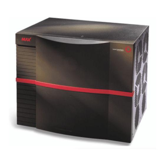
Blank single-slot filler cards for any unused slots in the unit. Checking the package contents MAX TNT package contents vary, depending on the base unit and slot cards you order. After opening the package verify that you have the system you ordered. Figure 2-1 shows a MAX TNT shelf. -
Page 23: Selecting The Installation Site
Preparing for Installation Selecting the installation site Selecting the installation site Before you choose a setup location for a MAX TNT unit, read and follow the site and electrical requirements defined in Appendix C, “Safety-Related Electrical, Physical, and Environmental Information.”... -
Page 24: Understanding The Unit's Back Panel
Understanding the unit’s back panel Understanding the unit’s back panel Figure 2-2 shows the back panel of a MAX TNT unit. The shelf controller is always slot 17. The remaining slots are numbered 1 through 16. For information about installing a slot card in a slot, see Chapter 3, “Installing a MAX TNT Chassis.”... -
Page 25: Understanding The Shelf-Controller Back Panel
Before you begin installing the hardware, you need some understanding of the ports and other items on the MAX TNT shelf controller. Figure 2-3 shows the location and Table 2-1 describes the function of each element on the shelf controller. -
Page 26: Status Lights On The Shelf-Controller Back Panel
Understanding the shelf-controller back panel Status lights on the shelf-controller back panel The status lights (also called LEDs) on the MAX TNT back panel can be helpful if you experience a problem, especially if it occurs shortly after power on. Figure 2-4 shows the location of the status lights on the back panel and Table 2-2 describes them. - Page 27 Light Color Description Green On when the Ethernet link is active and link integrity has been confirmed. Green On when there is Ethernet activity between MAX TNT shelves. Yellow On when an Ethernet collision occurs. MAX TNT Hardware Installation Guide...
-
Page 29: Installing A Max Tnt Chassis
Connecting the MAX TNT ac power supply ....... . 3-10... -
Page 30: Rack-Mounting A Max Tnt Unit
Installing a MAX TNT Chassis Rack-mounting a MAX TNT unit • Racks with open sides are recommended because the MAX TNT fans vent on the side of the unit. • Ensure adequate cooling in the room. – The maximum recommended ambient temperature for MAX TNT models is 104°... -
Page 31: Figure 3-1 Installing The Max Tnt Rack Ears
19 Inch kit (shown) Part No. TNT-RM19 23 inch kit (not shown) Part No. TNT-SP-RM23 You can mount a MAX TNT unit in a 19-inch or 23-inch (48.26cm or 58.42cm) rack. A single MAX TNT shelf has the dimensions shown in Figure 3-2. -
Page 32: Figure 3-2 Max Tnt Dimensions
Installing a MAX TNT Chassis Rack-mounting a MAX TNT unit Figure 3-2. MAX TNT dimensions 14.0" 17.4" 11.5" MAX TNT Hardware Installation Gulide... -
Page 33: Figure 3-3 Mounting The Max Tnt In A Rack
Installing a MAX TNT Chassis Rack-mounting a MAX TNT unit To install a MAX TNT unit in a rack, proceed as follows: Using a mechanical lift (recommended) or a minimum of two installers, raise the unit to the proper height for installation. -
Page 34: Installing A Max Tnt Exhaust Shield
Installing a MAX TNT exhaust shield Installing a MAX TNT exhaust shield You can install an exhaust shield on a rack-mounted MAX TNT unit. The exhaust shield redirects hot air from the unit so that it is not being blown into adjacent units. Figure 3-4 illustrates how to install the exhaust shield in a rack. -
Page 35: Installing Or Replacing High-Output Power Supplies
Although this card is not used for the high-output power supplies, it must be left in place when installing a high-output power supply to direct the airflow and help cool the unit. New MAX TNT units contain a plate in this space to reduce EMI. -
Page 36: Installing A High-Output Power Supply
Unscrew the power supply units from the chassis as shown in Figure 3-7. Figure 3-7. Unscrewing the power supply Caution: Do not remove the power supply capacitor card located below the MAX TNT power supplies. Doing so will disrupt airflow within the MAX TNT chassis. -
Page 37: Figure 3-8 Removing The Power Supply
Installing a MAX TNT Chassis Installing or replacing high-output power supplies Remove the existing power supplies as shown in Figure 3-8. Figure 3-8. Removing the power supply Gently insert the new power supply as shown in Figure 3-9. Figure 3-9. Inserting the power supply... -
Page 38: Connecting The Max Tnt Ac Power Supply
Solid copper wire (14 AWG or 2.5mm²) must be used to connect the power supply terminal block ground to the facility’s ground. If the MAX TNT unit is fed from an isolated supply, you must supply a solid ground to earth via copper rods. This ground must have a resistance of less than 5 ohms. -
Page 39: Connecting A Workstation To The Serial Port
Warning: Before installing wires to the unit’s dc power terminal block, verify that these wires are not connected to any power source and that the MAX TNT power supply switch is in the Off (down) position. Installing live wires (wires connected to a power source) is hazardous. -
Page 40: Connecting A Max Tnt Unit To The Lan
No flow control Connecting a MAX TNT unit to the LAN All MAX TNT systems have an Ethernet port on the shelf controller. This Ethernet port is designed primarily for out-of-band management over the network and is not intended to support heavy traffic loads. -
Page 41: Checking The Presence Of The Pcmcia Card
Checking the presence of the PCMCIA card Checking the presence of the PCMCIA card Each MAX TNT shelf supports up to two PCMCIA flash-memory cards. The system comes with onboard nonvolatile RAM (NVRAM), and each flash card provides its own additional memory. -
Page 42: Powering On A Max Tnt Unit
Powering on a MAX TNT unit Powering on a MAX TNT unit Note: Before powering on an unconfigured MAX TNT unit, you must connect it to a workstation. For instructions see “Connecting a workstation to the serial port” on page 3-11. -
Page 43: Installing Or Replacing Slot Cards
Identifying slot cards Some early slot cards produced for both the MAX TNT and APX chassis have long lock screws that extend about 3/16 inch (0.48cm) from the front panel. Slot cards originally produced for only the MAX TNT chassis have short lock screws that extend about 1/16 inch (.16cm) from the front panel. -
Page 44: Installing A Long-Lock-Screw Slot Card
Figure 3-15. Identifying long, medium, and short lock screws Installing a long-lock-screw slot card To install a long-lock-screw slot card in the MAX TNT chassis, proceed as follows: Hold the slot card so that the panel is facing you and the lock screw is on the left, and insert the card into the open slot as shown in Figure 3-16. -
Page 45: Installing A Short Or Medium Length Lock-Screw Slot Card
Jack screw Installing a short or medium length lock-screw slot card To install a short or medium length lock-screw slot card in the MAX TNT chassis, proceed as follows: Hold the slot card so that the panel is facing you and the lock screw is on the left, and insert the card into the open slot as shown in Figure 3-16. -
Page 46: Removing Slot Cards
Figure 3-17). Finish tightening the jack screw. All MAX TNT slot cards are hot-swappable, which means that you can safely insert or remove cards while power is on. Note: Be sure to install blank single-slot filler cards in any unused slots to ensure proper airflow. - Page 47 Unchannelized DS3 card ..........A-33 Note: Slot card information in this appendix is limited to physical specification and connection information. For slot card software profiles, line attributes, and configuration information, see the APX 8000/MAX TNT Physical Interface Configuration Guide. MAX TNT Hardware Installation Guide...
-
Page 48: Figure A-1 Ds3-Atm Card
DS3-ATM card DS3-ATM card The DS3-ATM card (shown in Figure A-1) enables a MAX TNT unit to provide one active and one standby trunk connection at data rates of 44.738Mbps. You can configure each port as one of the following types of connections: •... -
Page 49: Appendix A Slot Card Specifications And Connection Information
All status lights except LA are illuminate upon startup or restart and remain illuminated until the card passes its POST. If no status lights are illuminated, the DS3 interface is disabled or is receiving an Alarm Indication Signal (AIS) or Idle Signal. MAX TNT Hardware Installation Guide... -
Page 50: Connecting The Ds3-Atm Card To The Wan
Connecting redundant DS3-ATM cards You can install two DS3-ATM cards to provide redundancy. After installing the cards, configure line profiles for each card as explained in the APX 8000/MAX TNT/DSLTNT Physical Interface Configuration Guide. Figure A-2 illustrates a redundant connection. -
Page 51: Ds3-Atm2 Card
On indicates that the DS3 interface is experiencing loss of receive signal. Yellow On indicates that the DS3 interface is experiencing loss of framing. Yellow On indicates that the DS3 interface has detected a Far End Receive indication transmitted from the other side. MAX TNT Hardware Installation Guide... -
Page 52: Connecting The Ds3-Atm2 Card To The Wan
For information about configuring a redundant connection, see the APX 8000/MAX TNT/DSLTNT Physical Interface Configuration Guide. Figure A-4 shows a redundant connection. -
Page 53: E1 Card
Per G.704 frame alignment signal (FAS) with or without cyclic redundancy check 4 (CRC4) multiframe alignment (MFA). No channel-associated signaling (CAS) MFA used for data. Alarm signaling Red alarm, out of frame (OOF), FAS, alarm indication signal (AIS), and yellow alarm MAX TNT Hardware Installation Guide... -
Page 54: Figure A-6 Connecting A Max Tnt Unit's E1 Line To The Wan
Use cable that is specifically constructed for transmission of E1/PRI signals (CCITT G700 series recommended). • A MAX TNT unit can connect to any DPNSS access point on a PBX or directly to E1 digital services. The unit can also connect to G.704 framed leased (nonswitching) services for 75-ohm connections. -
Page 55: Monitoring The E1 Lines With Bantam Jacks
Each E1 card provides transmit and receive bantam jacks to monitor the status of the E1 lines. The Tx line carries what the MAX TNT unit transmits to the network. The Rx line carries what the unit receives from the network. The bantam jacks do not interfere with the signal either coming into or going out of the unit. -
Page 56: E3-Atm Card
34.368Mbps, for routing applications. Two E3-ATM slot cards in the same unit can be connected and configured for redundancy. MAX TNT units support up to two E3-ATM connections (two slot cards, or up to four cards configured redundantly). -
Page 57: Status Lights
ATM cells. FAULT Yellow Behaves as follows: • Illuminates when you restart a unit. • Goes out after the unit passes its power-on self test (POST). • Blinks if a fatal error has occurred. MAX TNT Hardware Installation Guide A-11... -
Page 58: Connecting An E3-Atm Slot Card To The Wan
You can install two E3-ATM slot cards to provide redundancy. If the primary card either fails to boot up or is in a fault state, the secondary slot card takes over. For information about configuring a redundant connection, see the APX 8000/MAX TNT/DSLTNT Physical Interface Configuration Guide. -
Page 59: Ethernet-2 Card
Must meet Japanese Industrial Standards (JIS) C 5973. Card dimensions 8.8 inches high x 10.6 inches long (22.35cm x 26.92cm) Card weight 3.9 pounds (1.77kg) Operating humidity 10-90%, noncondensing Operating temperature 32-104° F (0-40° C) MAX TNT Hardware Installation Guide A-13... -
Page 60: Ethernet-3 Card
Table A-10. Ethernet-3 card status lights Light Color Description Yellow On indicates activity on 10Mbps link. Yellow On indicates connection to 10Mbps link. Green On indicates activity on 100Mbps link. Green On indicates connection to 100Mbps link. A-14 MAX TNT Hardware Installation Guide... -
Page 61: Ethernet 3-Nd Card
Slot Card Specifications and Connection Information Ethernet 3-ND card Ethernet 3-ND card Ethernet 3-ND (no dongle) slot cards for APX/MAX TNT units have four full-duplex 10/100 megabit (Mb) Ethernet ports. The Ethernet 3-ND slot card is an enhancement of the Ethernet-3 slot card. -
Page 62: Hybrid Access Cards
Control (HDLC) channel to process the HDLC-encapsulated data received from or sent to a WAN interface. Because the MAX TNT base system provides no HDLC resources, you might need to install a Hybrid Access slot card in your unit. Keep in mind that the Series56 II and Series56 III cards also provide up to 48 HDLC channels per slot card. -
Page 63: Multidsp Cards
• Data and V.110 services Downloaded software licenses (hash codes) determine which MultiDSP services are supported by a particular MAX TNT unit and 96-port MultiDSP card. For example, if a unit is licensed to MAX TNT Hardware Installation Guide A-17... -
Page 64: Table A-13 Multidsp Card Specifications
96 ports of supported application per 96-port MultiDSP card Power requirements 37W, 7.4A Card weight ~1.5 pounds (0.7kg) Hot swap capability Status light Multipurpose fault indicator, one per card Operating humidity 10-90%, noncondensing Operating temperature 32-104° F (0-40° C) A-18 MAX TNT Hardware Installation Guide... -
Page 65: Oc3-Atm Card
The OC3-ATM card can be used to route IP over ATM or perform Layer 2 switching between ATM and Frame Relay networks. Note: A MAX TNT unit must have software version 7.0.1 or later to support the OC3-ATM card. Specifications Table A-14 lists the specifications for the OC3-ATM card. -
Page 66: Table A-15 Oc3-Atm Card Status Lights
On indicates the OC3 interface link is active and has not detected any error conditions. On indicates the OC3 interface has lost its frame alignment. On indicates the OC3 interface is experiencing loss of receive signal. A-20 MAX TNT Hardware Installation Guide... -
Page 67: Pctfi Card
A peripheral control and timing facilities interface (PCTFI) slot card connects a time slot interchanger (TSI) in a 5ESS SM-2000 switch with a MAX TNT unit. The PCTFI eliminates separate T1 (or E1) digital trunk interfaces in the switch, providing higher speed and broader connectivity between the 5ESS switch and MAX TNT unit. -
Page 68: Connecting The Pctfi Slot Card To The Switch
Each peripheral control and timing (PCT) facility interface link is a duplexed connection, with one active and one standby link. The 5ESS switch determines which side of the duplex PCT facility interface is selected for data transmission. A-22 MAX TNT Hardware Installation Guide... -
Page 69: Series56 Digital Modem Cards
Interfaces per card No external interfaces Connectors Card dimensions 8.8 inches high x 10.6 inches long (22.35cm x 26.92cm) Card weight 3.9 pounds (1.77kg) Operating humidity 10-90%, noncondensing Operating temperature 32-104° F (0-40° C) MAX TNT Hardware Installation Guide A-23... -
Page 70: Card
Signaling System 7 (SS7) data trunk. When the STM-0 card is configured for SS7 data trunks, the signaling gateway takes control of the data trunks, instructing the MAX TNT unit when to establish or dismantle calls. The STM-0 card does not support Call-Routing profiles, PRI signaling, or inband signaling. -
Page 71: Table A-20 Stm-0 Card Status Lights
3ms or more. Out-of-frame condition on the STM-0 line. The STM-0 slot card has detected absence of a valid framing pattern on the line. MAX TNT Hardware Installation Guide A-25... -
Page 72: Swan Card
8Mbps. The card provides direct connections to routers or packet switches (Frame Relay connections). Its circuitry includes hardware-based Stac compression. Up to six SWAN cards can be used in a MAX TNT shelf for a total of up to 24 ports. Figure A-15 shows the SWAN card. -
Page 73: Connecting The Swan Card To The Wan
Connect the other end of the cable to the V.35 port on a Frame Relay switch or to your WAN interface. Inform your service provider that the equipment is connected, so the provider can activate the line. MAX TNT Hardware Installation Guide A-27... -
Page 74: T1 Card
Receive equalization Based on cable length and transmitter Rx sensitivity 0 to -36dB Line code Alternate mark inversion (AMI) and bipolar 8-zero substitution (B8ZS) Line rate 1.544Mbps ± 32ppm Frame format Per ANSI T1.107a A-28 MAX TNT Hardware Installation Guide... -
Page 75: Connecting The T1 Card To The Wan
Each T1 card provides transmit and receive bantam jacks to monitor the status of the T1 lines. The Tx line carries what the MAX TNT unit transmits to the network. The Rx line carries what the unit receives from the network. The bantam jacks do not interfere with the signal either coming into or going out of the unit. -
Page 76: T1 Frameline Card
Based on cable length and transmitter Line code AMI, B8ZS Line rate 1.544Mbps ± 32ppm Frame format Per ANSI T1.107a (M23 or C-bit parity) Alarm signaling Red Alarm, yellow signal Connectors 10 RJ-45 (100-ohm line) A-30 MAX TNT Hardware Installation Guide... -
Page 77: T3 Card
When a DS3 Red Alarm occurs, a Yellow Alarm is sent on the DS3 line and an AIS is sent on DS2 lines. Upon a DS2 Red Alarm, AIS is sent on DS1s. Connectors Four 75-ohm BNC coaxial (two lines and two backup lines). MAX TNT Hardware Installation Guide A-31... -
Page 78: Connecting The T3 Card To The Wan
Bypass Rx and Bypass Tx jacks, respectively. When the T3 card passes its POST, a relay switch connects the line jacks to the card’s T3 transceiver. Inform your service provider that the equipment is connected, so the provider can activate the line. A-32 MAX TNT Hardware Installation Guide... -
Page 79: Unchannelized Ds3 Card
A second set of BNC connectors on the card can be connected to a second DS3 card for redundant operation. Each MAX TNT chassis can contain up to two unchannelized DS3 cards. -
Page 80: Connecting The Unchannelized Ds3 Card To The Wan
When the UDS3 card passes its POST, a relay switch connects the Line jacks to the card’s T3 transceiver. Inform your service provider that the equipment is connected, so the provider can activate the line. A-34 MAX TNT Hardware Installation Guide... -
Page 81: Appendix B Cabling And Connector Specifications
SDSL cable specifications ..........B-27 MAX TNT units support a variety of interfaces. Each interface has its own specifications and cabling requirements. -
Page 82: Ethernet Interface Specifications
For an AUI interface, you need the appropriate transceiver and transceiver cable. T1/PRI interface specifications Specifications for a MAX TNT unit’s T1/PRI interface include channel service unit (CSU) requirements, specifications for the cables and the plugs available for the unit’s WAN interfaces, the pins to be used on the WAN ports, and the WAN switched services that are available to the MAX TNT unit. -
Page 83: T1/Pri Csu Requirements
(CSU). Port with internal CSU If a T1/PRI port on the MAX TNT unit has an internal CSU, you can connect the port directly to the metallic interface of the WAN. To avoid harming the WAN, you must contact your carrier for approval before installation. -
Page 84: T1/Pri Cable Specifications
The maximum cable distance between the T1/PRI WAN interface equipment and a MAX TNT unit without CSUs should not exceed 655 feet (200m). Measure the line length and record it when you install the MAX TNT unit. You must specify this length when you configure the parameters in the line’s profile. -
Page 85: Figure B-2 Rj-48C/Rj-48C Straight-Through Cable
Table B-4. RJ-48C/RJ-48C straight-through cable specifications Pair # Signal Male RJ-48C Male RJ-48C Receive Transmit Figure B-2. RJ-48C/RJ-48C straight-through cable RECEIVE 1 RECEIVE 2 5 TRANSMIT TRANSMIT 4 4 TRANSMIT TRANSMIT 5 2 RECEIVE 1 RECEIVE Male RJ-48C Male RJ-48C MAX TNT Hardware Installation Guide... -
Page 86: Figure B-3 Rj-48C/Db-15 Straight-Through Cable
Table B-5. RJ-48C/DB-15 straight-through cable specifications Pair # Signal Male RJ-48C Male DB-15 Receive Transmit Figure B-3. RJ-48C/DB-15 straight-through cable 5 TRANSMIT 4 TRANSMIT 2 RECEIVE 11 TRANSMIT TRANSMIT 3 1 RECEIVE 9 RECEIVE RECEIVE 1 Male DB-15 Male RJ-48C MAX TNT Hardware Installation Guide... -
Page 87: Figure B-4 Rj-48C/Db-15 Crossover Cable
Pair # Signal Male RJ-48C Male DB-15P Receive Transmit Figure B-4. RJ-48C/DB-15 crossover cable Male RJ-48C 5 TRANSMIT 4 TRANSMIT 2 RECEIVE 11 TRANSMIT TRANSMIT 3 1 RECEIVE 9 RECEIVE RECEIVE 1 Male DB-15 Male RJ-48C MAX TNT Hardware Installation Guide... -
Page 88: Figure B-5 Rj-48C/Bantam Straight-Through Cable
Transmit Tip 2 Ring 2 Figure B-5. RJ-48C/Bantam straight-through cable TIP 1 RECEIVE RING 1 RECEIVE 5 TRANSMIT 4 TRANSMIT RING 2 TRANSMIT 2 RECEIVE TIP 2 TRANSMIT 1 RECEIVE Male Dual 310-P Male RJ-48C MAX TNT Hardware Installation Guide... -
Page 89: T1/Pri Wan Connectors
• MultiRate and GloBanD (and GVPN in CCITT countries) PRI network services Note: MAX TNT units can only access Switched-56Kbps services on a T1 access line or a Switched-56 line. For a listing of the compatible switch types, see the Switch Type parameter listing in the APX 8000/MAX TNT Reference. -
Page 90: E1/Pri Interface Specifications
Cabling and Connector Specifications E1/PRI interface specifications E1/PRI interface specifications MAX TNT E1/PRI specifications apply to cables and WAN ports. E1/PRI cable specifications The WAN interface cables and plugs described in this section are available for the unit’s WAN interfaces. -
Page 91: Figure B-7 Rj-48C/Rj-48C Straight-Through Cable
2 and 1 and receives on pins 5 and 4. Table B-11 and Figure B-7 show the pinouts. Table B-11. RJ-48C/RJ-48C straight-through cable specifications Model number RJ-48C-S Part number 2510-0064-001 Pair # Signal Male RJ-48C Male RJ-48C (MAX TNT) (MAX TNT) (remote) Receive Transmit Figure B-7. RJ-48C/RJ-48C straight-through cable MAX TNT Hardware Installation Guide B-11... -
Page 92: Figure B-8 Rj-48C/Da-15 Straight-Through Cable
3 and 11 and receives on pins 1 and 9. Figure B-8 and Table B-12 show the pinouts. Table B-12. RJ-48C/DA-15 straight-through cable specifications Model number DA15-X Part number 2510-0082-001 Pair # Signal Male RJ-48C Male DA-15 (remote) Receive Transmit Figure B-8. RJ-48C/DA-15 straight-through cable B-12 MAX TNT Hardware Installation Guide... -
Page 93: Figure B-9 Rj-48C/Da Crossover Cable
9 and receives on pins 3 and 11. Figure B-9 and Table B-13 show the pinouts. Table B-13. RJ-48C/DA crossover cable specifications Model number DA15-S Part number 2510-0065-001 Pair # Signal Male RJ-48C Male DA-15 (remote) Receive Transmit Figure B-9. RJ-48C/DA crossover cable MAX TNT Hardware Installation Guide B-13... -
Page 94: Figure B-10 Rj-48C/Bantam Straight-Through Cable
Table B-14. RJ-48C/Bantam straight-through cable specifications Model number DBNT-RJ-48C Part number 2510-0066-001 Pair # Signal Male RJ-48 Male Dual-310-P (remote) Receive Tip 1 Ring 1 Transmit Tip 2 Ring 2 Figure B-10. RJ-48C/Bantam straight-through cable B-14 MAX TNT Hardware Installation Guide... -
Page 95: E1/Pri Wan Ports
Serial WAN (SWAN) cable specifications E1/PRI WAN ports Table B-15 lists the pins on RJ-48C sockets used for E1/PRI WAN interface on the MAX TNT. Only pins 1, 2, 4, and 5 are used. The remaining pins are not connected. -
Page 96: Serial Wan (Swan) Cable Specifications
Cabling and Connector Specifications Serial WAN (SWAN) cable specifications Table B-16. V.35 cable pinouts (continued) Pair # Signal MAX TNT male Host male V.35 DB-44 SGND B-16 MAX TNT Hardware Installation Guide... -
Page 97: Rs-449 Cable To Wan
RS-449 cable has the pinouts described in Table B-17. Table B-17. RS-449 cable pinouts Pair # Signal MAX TNT male Host female DB-37 DB-44 FGND SGND 19, 20, 37* * Pin positions separated by commas are jumped to each other. MAX TNT Hardware Installation Guide B-17... -
Page 98: Serial Wan Cable
Cabling and Connector Specifications Serial WAN (SWAN) cable specifications Serial WAN cable Figure B-11 and Table B-18 show the pinouts for the V.35 serial WAN (SWAN) cable. Table B-18. Serial WAN cable pinouts J1 Pin J2 Pin B-18 MAX TNT Hardware Installation Guide... -
Page 99: Figure B-11 Serial Wan Cable
Cabling and Connector Specifications Serial WAN (SWAN) cable specifications Figure B-11. Serial WAN cable MAX TNT Hardware Installation Guide B-19... -
Page 100: Table B-19 Idsl Cable Pinouts
Tip 4 Ring 4 Tip 5 Ring 5 Tip 6 Ring 6 Tip 7 Ring 7 Tip 8 Ring 8 Tip 9 Ring 9 Tip 10 Ring 10 Tip 11 Ring 11 Tip 12 B-20 MAX TNT Hardware Installation Guide... - Page 101 Ring 16 Tip 17 Ring 17 Tip 18 Ring 18 Tip19 Ring 19 Tip 20 Ring 20 Tip 21 Ring 21 Tip 22 Ring 22 Tip 23 Ring 23 Tip 24 Tip 24 Tip1 MAX TNT Hardware Installation Guide B-21...
- Page 102 Tip 6 Ring 6 Tip 7 Ring 7 Tip 8 Ring 8 Tip 9 Ring 9 Tip 10 Ring 10 Tip 11 Ring 11 Tip 12 Ring 12 Tip 13 Ring 13 Tip 14 B-22 MAX TNT Hardware Installation Guide...
- Page 103 Tip 16 Ring 16 Tip 17 Ring 17 Tip 18 Ring 18 Tip19 Ring 19 Tip 20 Ring 20 Tip 21 Ring 21 Tip 22 Ring 22 Tip 23 Ring 23 Tip 24 Tip 24 MAX TNT Hardware Installation Guide B-23...
-
Page 104: Idsl Cable Specifications
Cabling and Connector Specifications IDSL cable specifications Figure B-12. HDSL dual 50-pin telco-to-triple-DB-37 cable All three ends above have same pinouts: Both ends above have same pinouts: B-24 MAX TNT Hardware Installation Guide... -
Page 105: Adsl Cable Specifications
Tip 4 Ring 4 Tip 5 Ring 5 Tip 6 Ring 6 Tip 7 Ring 7 Tip 8 Ring 8 Tip 9 Ring 9 Tip 10 Ring 10 Tip 11 Ring 11 Tip 12 MAX TNT Hardware Installation Guide B-25... - Page 106 Tip 16 Ring 16 Tip 17 Ring 17 Tip 18 Ring 18 Tip19 Ring 19 Tip 20 Ring 20 Tip 21 Ring 21 Tip 22 Ring 22 Tip 23 Ring 23 Tip 24 Tip 24 B-26 MAX TNT Hardware Installation Guide...
-
Page 107: Figure B-13 Adsl 50-Pin Telco-To-Quadruple Db-37 Cable
Figure B-14 and Table B-21 show the pinouts for the 50-pin telco-to-dual-DB-37 SDSL cable. Table B-21. SDSL cable pinouts Pair P1 Pin P2 Pin J1 Pin Signal Tip1 Ring 1 Tip 2 Ring 2 Tip 3 Ring 3 Tip 4 Ring 4 Tip 5 MAX TNT Hardware Installation Guide B-27... - Page 108 Tip 10 Ring 10 Tip 11 Ring 11 Tip 12 Ring 12 Tip 13 Ring 13 Tip 14 Ring 14 Tip 15 Ring 15 Tip 16 Ring 16 Tip 17 Ring 17 Tip 18 B-28 MAX TNT Hardware Installation Guide...
-
Page 109: Table B-22 Cable Pinouts For The 50-Pin Telco Connector
The high-performance SDSL data card uses a universal service order code (USOC) RJ-21X 50-pin telco connector. Cable pinouts are shown in Table B-22. Table B-22. Cable pinouts for the 50-pin telco connector Signal Signal 1R (channel 1 ring) 1T (channel 1 tip) MAX TNT Hardware Installation Guide B-29... -
Page 110: Sdsl Cable Specifications
Table B-22. Cable pinouts for the 50-pin telco connector (continued) Signal Signal -48v (return) -48v Pins 25 and 50 are used only to provide sealing current. To run sealing current, a 48V battery is connected between pins 25 and 50. B-30 MAX TNT Hardware Installation Guide... -
Page 111: Figure B-14 Sdsl 50-Pin Telco-To-Dual-Db-37 Cable
Cabling and Connector Specifications SDSL cable specifications Figure B-14. SDSL 50-pin telco-to-dual-DB-37 cable MAX TNT Hardware Installation Guide B-31... -
Page 113: Appendix C Safety-Related Electrical, Physical, And Environmental Information
Electronic and electrical specifications Battery The MAX TNT shelf controller contains an internal 3V lithium battery. The normal operating life of this battery exceeds five years. Make sure that only trained engineers authorized by Lucent open the MAX TNT shelf controller for testing, maintenance, installation, or any other purpose. -
Page 114: Electrical Requirements
Dc: 40A (circuit breaker) Because the MAX TNT configuration profiles are stored in NVRAM, they are not lost when the unit is turned off. Note: Use a protected ac power source, or add surge protection between the power source and the unit. -
Page 115: Usoc Jacks And Codes
RJ-48C Alarm-relay operating specifications MAX TNT units are equipped with an alarm relay whose contacts are brought out onto the back panel’s alarm-relay terminal block. The alarm-relay contacts close during loss of power, during hardware failure, or whenever the unit is being reset, such as during its power-on self test (POST). -
Page 116: Environmental Specifications
Environmental specifications Environmental specifications For best results, house the MAX TNT unit in a room with constant temperature and humidity. In general, cooler environments are better. Humidity must be high enough to prevent accumulation of static electricity, but low enough to prevent condensation. -
Page 117: Index
A-33 V.35 B-15 E3 lines connecting to the WAN A-13 configuration accessing configuration interface through serial cable E3-ATM card 3-11 indicators A-12 redundant connection A-13 connections redundant T3 A-33 specifications A-11 connectors electronic specification MAX TNT Hardware Installation Guide Index-1... - Page 118 A-20 cabling specifications B-20 status lights A-21 installation connecting to the LAN 3-12 installing the MAX TNT chassis maximum distance between MAX TNT and WAN interface equipment PCMCIA card overview danger removing 3-13 power supplies verifying integrity of 3-14 preparing for...
- Page 119 SDSL card cabling for B-27 switch preparing for installation serial port connecting MAX TNT to 3-11 Switched-56 services, how the MAX TNT can access specifications for serial WAN cabling specifications B-15 serial WAN card cabling for A-28 connecting to WAN A-28 V.35 cabling for...
- Page 120 E1 line to connecting E3 line to A-13 connecting T1 line to A-30 connecting T3 card to A-33 WAN (Wide Area Network) ports E1/PRI connector specifications B-15 wire gauge, wire connecting to alarm relay Index-4 MAX TNT Hardware Installation Guide...
Need help?
Do you have a question about the MAX TNT and is the answer not in the manual?
Questions and answers