Table of Contents
Advertisement
Quick Links
Advertisement
Table of Contents

Subscribe to Our Youtube Channel
Related Manuals for Thecus N8800 IP


Summary of Contents for Thecus N8800 IP
- Page 1 Thecus N8800 FW v3.00.06 User’s Manual...
-
Page 2: Copyright And Trademark Notice
About This Manual All information in this manual has been carefully verified to ensure its correctness. In case of an error, please provide us with your feedback. Thecus Technology Corporation reserves the right to modify the contents of this manual without notice. -
Page 3: Safety Warnings
Safety Warnings For your safety, please read and follow the following safety warnings: Read this manual thoroughly before attempting to set up your N8800. Your N8800 is a complicated electronic device. DO NOT attempt to repair it under any circumstances. In the case of malfunction, turn off the power immediately and have it repaired at a qualified service center. -
Page 4: Table Of Contents
Checking System Status ..............16 System Status Normal ................16 System Trouble ..................16 Chapter 3: First Time Setup ............17 Overview .....................17 Thecus Setup Wizard ................17 LCD Operation ..................19 LCD Co ntrols ..................19 Display Mode ..................19 USB Cop y ...................... - Page 5 System Information................25 Product Information ................25 System /Service Status ................26 Logs ..................... 27 System Management ................28 Time: S etting system time ............... 28 Notifica tion configuration ................. 28 Firmwa re Upgrade .................. 29 UPS Se tting ................... 30 Schedul e Power On/Off ................
- Page 6 Nsync Target on an Nsync Device ............94 Setting U p an Nsync Target on Another Device............95 Designa ting N8800 as an Nsync Target ..............95 Thecus Backup Utility ................95 Window s XP Data Backup................. 96 Apple O S X Backup Utilities ..............
- Page 7 Part III - Setting up Virtual Servers (HTTPS)..........115 Firewall Software Configuration ............115 Replacing Damaged Hard Drives............116 Hard Dr ive Damage................116 Replacin g a Hard Drive ................116 RAID Au to-Rebuild ................116 Chapter 7: Troubleshooting ............117 Forgot My Network IP Address ............
-
Page 8: Chapter 1: Introduction
Chapter 1: Introduction Overview Thank you for choosing the Thecus N8800 IP Storage Server. The Thecus N8800 is an easy-to-use storage server that allows a dedicated approach to storing and distributing data on a network. Data reliability is ensured with RAID features that provide data security and recovery—over ten Terabyte of storage is available using... -
Page 9: Printer Server
Backup Server Don’t leave precious data to chance. With advanced backup capabilities, you can easily upload mission critical files to the N8800, and even automate your backup tasks for true peace-of-mind. To find out how to backup your files with the N8800, refer to Chapter 4: Backup >Nsync. - Page 10 Screw Kit & Key-Luck x1 HDD Compatibility list Card x1 Multiple Languages Warranty Card x1 Please check to see if your package is complete. If you find that some items are missing, contact your dealer.
-
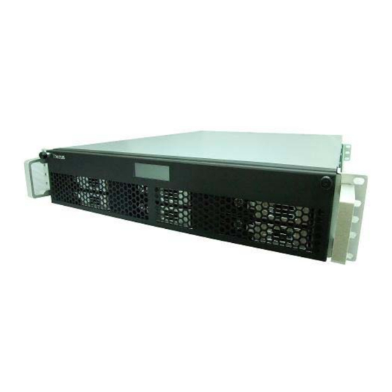
Page 11: Front Panel
Front Panel The Thecus N8800’s front panel has the device’s controls, indicators, and hard disk trays: Front Panel Item Description 1.Power Button • Power on/off N8800 2.Power LED • Solid green: System is power on. 3.Reboot Button • Press to system reboot 4.System fan alarm... -
Page 12: Hard Disk Trays
Hard Disk Trays Each of the N8800’s hard disk trays has a lock, a latch, and two LED indicators: Hard Disk Trays Item Description 1.HDD Power LED • Solid blue: hard disk is powered on 2.HDD • Blinking green: system is accessing data on the hard disk Access/Error LED 3.Lock •... - Page 13 5.Serial Port • This port is for external UPS device 6.WAN Port • WAN port for connecting to an Ethernet network through a switch or router 7.LAN Port • WAN port for connecting to an Ethernet network through a switch or router...
-
Page 14: Chapter 2: Hardware Installation
Chapter 2: Hardware Installation Overview Your N8800 is designed for easy installation. To help you get started, the following chapter will help you quickly get your N8800 up and running. Please read it carefully to prevent damaging your unit during installation. Before You Begin Before you begin, be sure to take the following precautions: 1. -
Page 15: Cable Connections
Cable Connections To connect the N8800 to your network, follow the steps below: 1. Connect an Ethernet cable from your network to the WAN port on the back panel of the N8800. 2. Connect the provided power cord into the universal power socket on the back panel. -
Page 16: Checking System Status
Checking System Status After making connections on the N8800 and powering up, check whether the system status is normal or has trouble by observing indicators on the front panel and hard disk trays. System Status Normal The system status is normal if: The Power LED on the Front Panel glows green. -
Page 17: Chapter 3: First Time Setup
N8800 so that it is accessible to your network users. There are two ways to set up your N8800: using the Thecus Setup Wizard or the LCD display. Follow the steps below for initial software setup. - Page 18 6. Name your N8800 and configure the network IP address. If your switch or router is configured as a DHCP Server, configuring the N8800 to automatically obtain an IP address is recommended. You may also use a static IP address and enter the DNS Server address manually. 7.
-
Page 19: Lcd Operation
The Thecus Setup Wizard is designed for installation on systems running Windows NOTE XP/2000 or Mac OSX or later. Users with other operating systems will need to install the Thecus Setup Wizard on a host machine with one of these operating systems before using the unit. LCD Operation The N8800 is equipped with an LCD on the front for easy status display and setup. -
Page 20: Usb Copy
2009/05/22 12:00 Current system time. Disk Info Current status of disk slot has been installed RAID Current RAID status. The N8800 will rotate these messages every one-two seconds on the LCD display. USB Copy The USB Copy function enables you to copy files stored on USB devices such as USB disks and digital cameras to the N8800 by press button. -
Page 21: Step 1: Network Setup
Step 1: Network Setup From the Web Administration Interface, you can configure the network settings of the N8800 for your network. You can access the Network menu from the menu bar. For details on how to configure your network settings, refer to Chapter 4: System Network Step 2: RAID Creation... - Page 22 Printer Server Photo Server...
-
Page 23: Chapter 4: System Administration
Chapter 4: System Administration Overview The N8800 provides an easily accessible Web Administration Interface. With it, you can configure and monitor the N8800 anywhere on the network. Web Administration Interface Make sure your network is connected to the Internet. To access the N8800 Web Administration Interface: 1. -
Page 24: Message Bar
Menu Bar Item Description System Information Current system status of the N8800. System Management Various N8800 system settings and information. System Network Information and settings for network connections, as well as various services of the N8800. Storage Information and settings for storage devices installed into the N8800. -
Page 25: Logout
Green: Systematic temperature is normal. Temperature. Red: Systematic temperature is unusual. Click to go to System Status page as short cut. Green: Connection to network is normal. Network. Red: abnormal connection to the network Logout Click to logout Web Administration Interface. Language Selection The N8800 supports multiple languages, including: English... -
Page 26: System/Service Status
Product Information Item Description Manufacturer Displays the name of the system manufacturer. Product No. Shows the model number of the system. Firmware version Shows the current firmware version. Up time Displays the total run time of the system. System/Service Status From the Status menu, choose the System item, System Status and Service Status screens appear. -
Page 27: Logs
Logs From the System Information menu, choose the Logs item and the System Logs screen appears. This screen shows a history of system usage and important events such as disk status, network information, and system booting. See the following table for a detailed description of each item: See the following table for a detailed description of each item: System Logs Item... -
Page 28: System Management
System Management The System Management menu gives you a wealth of settings that you can use to configure your N8800’s system administration functions. You can set up system time, system notifications, and even upgrade firmware from this menu. Time: Setting system time From the time menu, choose the Time item and the Time screen appears. -
Page 29: Firmware Upgrade
Notification Configuration Item Description Beep Notification Enable or disable the system beeper that beeps when a problem occurs. Email Notification Enable or disable email notifications of system problems. SMTP Server Specifies the hostname/IP address of the SMTP server. Port Specifies the port to send outgoing notification emails. Auth Type Select the SMTP Server account authentication type. -
Page 30: Ups Setting
• The beeper only beeps if it is enabled in the System Notification menu. NOTE • Check Thecus website for the latest firmware release and release notes. • Downgrading firmware is not permitted. Do not turns off the system during the firmware upgrade process. -
Page 31: Schedule Power On/Off
See the following table for a detailed description of each item. UPS Setting Item Description UPS Monitoring Enable or disable UPS monitoring. Manufacturer Choose the UPS manufacturer from the dropdowns. Model Choose the UPS model number from the dropdowns. Battery Status Current status of the UPS battery Power Current status of the power being supplied to the... -
Page 32: Wake-Up On Lan (Wol)
Example - Monday: On: 8:00; Off: 16:00 System will turn on at 8:00 AM on Monday, and off at 16:00 on Monday. System will turn on for the rest of the week. If you choose an on time, but do not assign an off time, the system will turn on and remain on until a scheduled off time is reached, or if the unit is shutdown manually. -
Page 33: Utility
From the menu, choose the SNMP item, and the SNMP Support screen appears. From here, you can Enable or Disable. Utility ˙ Administrator password From the menu, choose the Administrator Password item and the Change Administrator Password screen appears. Enter a new password in the New Password box and confirm your new password in the Confirm Password box. -
Page 34: Config Mgmt
Confirm Password Type the new password again to confirm. Apply Press this to save your changes. ˙ Config Mgmt From the menu, choose the Config Mgmt item and the System Configuration Download/Upload screen appears. From here, you can download or upload stored system configurations. - Page 35 ˙ Reboot & Shutdown From the menu, choose Reboot & Shutdown item, and the Shutdown/Reboot System screen appears. Press Reboot to restart the system or Shutdown to turn the system off. ˙ File System check The File System Check allows you to perform a check on the integrity of your disks’ file system.
- Page 36 Once the system has rebooted, you will be returned to the File System Check prompt. There you will see the available RAID volumes to run the file system check on except ZFS volume, ZFS has no need to perform file system check. Check the desired RAID volumes and click Next to proceed with the file system check.
-
Page 37: System Network
The system must be re booted before the N8800 can function normally NOTE after file system check co mplete. System Network Use the System Network menu to make network configuration settings as well as service support settings. WAN Configuration From the System Network menu, choose WAN, and the WAN Configuration screen appears. - Page 38 WAN Configuration Item Description Host name Host name that identifies the N8800 on the network. Domain name Specifies the domain name of the N8800. To set a server name for NetBIOS computer. WINS Server MAC Address MAC address of the network interface. Jumbo Frame Support Enable or disable Jumbo Frame Support of the WAN interface on your N8800.
-
Page 39: Lan
WARNING Most Fast Ethernet (10/100) Switches/Routers do not support Jumbo Frame and you will not be able to connect to your N8800 after Jumbo Frame is turned on. If this happens, turn off the N8800. Then, insert USB disk with factory reset utility included and power on the N8800. Till the system power on complete then it will bring your system settings back to factory default. -
Page 40: Samba / Cifs
The IP Segment of WAN and LAN should not overlap. NOTE The IP address of the LAN interface should not be in the range of the Start WARNING IP address and End IP address. Samba / CIFS There are 4 options is currently allow Admin to Enable/Disable to operate N8800 associated with Samba / CIFS protocol. -
Page 41: Samba Anonymous Login Authentication
Samba Anonymous Login Authentication To enable this option, no matter there is share folder has been created in public access. The user account and password is needed from system to access under SMB/CIFS protocol. On the other hand, no more anonymous login is allowed. •... -
Page 42: Nfs Set Ftp
A description of each item follows: NFS Server Setting Item Description Enable or Disable NFS support. Apply Click Apply to save your changes. N8800 can act as a FTP server, enabling users to download and upload files with their favorite FTP programs. From the System Network menu, choose the FTP item, and the FTP screen appears. -
Page 43: Media Server
Security FTP Enable or disable Security FTP, be sure the client FTP software has also security FTP setting enabled. Port Specifies the port number of an incoming connection on a non-standard port. FTP ENCODE If your FTP client or operating system does not support Unicode (e.g. -
Page 44: Share Media Folders
A description of each field follows: Media Manager Settings Item Description Media Server Enable or disable the Media Server service. Shared Media Folders Select the folder(s) that contains media files to be shared. Rescan Click the Rescan button to have the N8800 for new contents in the selected media folder. -
Page 45: Http/ Web Disk
4. Setup the DMA (These steps will be different if you use a different DMA) a. From the Server List screen, select “N8800: Media Server” as the server. b. Go to My Media c. Click on the Up/Down Arrow buttons to select Music Jukebox, Photo Albums, or Video Clips d. -
Page 46: Upnp
From the System Network menu, choose the Nsync Target item, and the Nsync Setting screen appears. Enable or Disable your Nsync Target Server. Press Apply to confirm your settings. Once Nsync Target has been enabled, the other Thecus NAS product is able to operate remote replication to this NAS system. Bonjour Setting Bonjour, is Apple Inc.'s trade name for its implementation of Zeroconf, a service... -
Page 47: Disks In
through Bonjour zero-configuration networking with a complete description of the protocols and technologies used to create Bonjour enabled applications and devices. Storage Management The Storage menu displays the status of storage devices installed in the N8800, and includes storage configuration options such as RAID and disk settings, folder configuration, space allocation and ISO Mount. -
Page 48: S.m.a.r.t. Information
Failed. Bad Block scan Yes to start scan Bad Block. Total Capacity Shows the total SATA hard disk capacity. Disk Power The administrator can set the disk to power down after a period of Management inactivity. When the Status shows Warning, it usually means there are bad sectors on the NOTE hard disk. -
Page 49: Bad Block Scan
reallocated, the more a decrease (up to 10% or more) can be noticed in disk read/write speeds. Current Pending Sector Current count of unstable sectors (waiting for remapping). The raw value of this attribute indicates the total number of sectors waiting for remapping. -
Page 50: Create A Raid
RAID Information Item Description Master RAID The RAID volume currently designated as the Master RAID volume. ID of the current RAID volume. NOTE: All RAID IDs must be unique. RAID Level Shows the current RAID configuration. Status Indicates status of the RAID. Can read either Healthy, Degraded, or Damaged. - Page 51 2. On the RAID Configuration screen, set the RAID storage space as JBOD, RAID 0, RAID 1, RAID 5, RAID 6, or RAID 10 — see Appendix C: RAID Basics for a detailed description of each. 3. Specify a RAID ID. 4.
-
Page 52: Raid Level
Building a RAID volume may take time, depending on the size of hard drives NOTE and RAID mode. In gene ral, while the RAID volume building process is up to “RAID Building” then th e data volume is capable to be accessed. Creating RAID destroys a ll data in the current RAID volume. -
Page 53: Edit Raid
RAID 5 requires a minimum of 3 disks. RAID 5 can sustain one failed disk. RAID 6 Two independent parity computations must be used in order to provide protection against double disk failure. Two different algorithms are employed to achieve this purpose. RAID 6 requires a minimum of 4 disks. -
Page 54: Remove Raid
Remove RAID Click to remove the RAID volume. All user data and iSCSI has been created in selected RAID volume will be removed. To remove a RAID volume, follow the steps below: 1. On the RAID List screen, select the RAID volume by clicking on its radio button, and click RAID Information to open the RAID Configuration screen. -
Page 55: Expanding A Raid
Remove RAID destroys a ll data in the current RAID volume. The data is WARNING unrecoverable. Expanding a RAID To expand a RAID 1, RAID 5, RAID 6, or RAID 10 volume, follow the steps below: 1. Replace one of the hard drives in the RAID volume and allow it to automatically rebuild. -
Page 56: Migrating A Raid
Migrating a RAID Once a RAID volume has been created, you may want to move it to other physical drives or change the RAID array all together. To migrate a RAID 0, RAID 1, RAID 5 or RAID 6 volume, follow the steps below: 1. - Page 57 NOTE Migrating a RAID volume could take several hours to complete With RAID level migration function, it has two different type “On line” and “Off line” alone with limitation as listed below. 1. During RAID level migration, it is not allowed reboot or shutdown system. 2.
- Page 58 Below is a table listing of possible RAID migration schemes: From RAID 0 RAID 5 RAID 6 [OFFLINE] [OFFLINE] RAID [RAID 0] HDDx2 to [RAID 0] HDDx3 [RAID 0] HDDx2 to [RAID 5] HDDx3 [RAID 0] HDDx2 to [RAID 0] HDDx4 [RAID 0] HDDx2 to [RAID 5] HDDx4 [RAID 0] HDDx2 to [RAID 0] HDDx5 [RAID 0] HDDx2 to [RAID 5] HDDx5...
-
Page 59: Space Allocation
[ONLINE] RAID [RAID 5] HDDx3 to [RAID 5] HDDx4 [RAID 5] HDDx3 to [RAID 5] HDDx5 [RAID 5] HDDx3 to [RAID 5] HDDx6 [RAID 5] HDDx3 to [RAID 5] HDDx7 [RAID 5] HDDx3 to [RAID 5] HDDx8 [RAID 5] HDDx4 to [RAID 5] HDDx5 [RAID 5] HDDx4 to [RAID 5] HDDx6 [RAID 5] HDDx4 to [RAID 5] HDDx7 [RAID 5] HDDx4 to [RAID 5] HDDx8... -
Page 60: Allocating Space For Iscsi Volume
Item Description Modify Click this to modify the allocated space. Delete Click this to delete the allocated space. iSCSI Target Click to allocate space to iSCSI volume. Type Type of volume. Can be either USB or iSCSI. Name Name assigned to the volume. Capacity Capacity of the allocated space. -
Page 61: Modify Iscsi Volume
Item Description RAID ID ID of current RAID volume. Allocation Percentage and amount of space allocated to iSCSI volume. Unused Percentage and amount of unused space on current RAID volume. iSCSI Target Volume Enable or Disable the iSCSI Target Volume. Target Name Name of the iSCSI Target. -
Page 62: Delete Volume
2. Modify your setting. Press ok to change. Delete Volume To delete volume on the current RAID volume, follow the steps below: 1. Under the Volume Allocation List, click Delete. The Space Allocation screen appears. -
Page 63: Advance Option
2. Press YES. All data in the volume will be removed. Advance Option There are 2 options is currently allow Admin to Enable/Disable to operate N8800 associated with iSCSI setting. The details as listed in following screenshot. With the option changed, it will need to reboot system to activate. iSCSI Block Size Select the block size with 4K while the iSCSI volume size is over 2TB. -
Page 64: Adding Folders
Adding Folders On the Folder screen, press the Add button and the Add Folder screen appears. This screen allows you to add a folder. After entering the information, press Apply to create new folder. -
Page 65: Modify Folders
Add Folder Item Description RAID ID RAID volume where the new folder will reside. Folder Name Enter the name of the folder. Description Provide a description the folder. Browseable Enable or disable users from browsing the folder contents. If Yes is selected, then the share folder will be browseable. -
Page 66: Remove Folders
Description Provide a description the folder. Browseable Enable or disable users from browsing the folder contents. This setting will only apply while access via SMB/CIFS and web disk. Public Admit or deny public access to this folder. Share Limit Enter the maximum size of the folder. The folder will not grow beyond this limit. - Page 67 NFS Share Item Description Hostname Enter the name or IP address of the host Privilege Host has either read only or writeable access to the folder. Guest System Support There are two selections available: • Unix / Linux System • AIX (Allow source port >...
-
Page 68: Snapshot
Snapshot The N8800 is capable for 16 snapshot version control. To have snapshot to work on, the file system creation for RAID volume has to be “ZFS”. Snap (Snapshot configuration) If added folder has located in the RAID volume with “ZFS” file system, then the folder management screen with “Snap”... -
Page 69: Folder And Sub-Folders Access Control List (Acl)
These taken snapshot is only accessible though CIFS/SMB by manually type \\NAS IP address\snapshot and invisible from normal access. Also, the taken snapshot version is read only can not be deleted under CIFS/SMB access but only click the “Del” button showing on the screen shot above. Folder and sub-folders Access Control List (ACL) On the Folder screen, press the ACL button, and the ACL setting screen appears. - Page 70 2. With the group or user selected, press one of the buttons from the three access level columns at the top. The group or user then appears in that column and has that level of access to the folder. 3. Continue selecting groups and users and assigning them access levels using the column buttons.
-
Page 71: Stackable Nas
The system will list up to 1,000 users from the chosen category. To narrow NOTE your search, ente r a search term in the blank provided. Stackable NAS The N8800’s capacity can be expanded even further using the stackable function. With it, users can expand the capacity of their network storage systems up to 5 other stack target volumes which are located in different systems. - Page 72 Next, input the target IP address of the stackable device and click the Discovery button. The system will list available target volumes from the inputted IP address. Once IP with volume have been set, you may need to input a valid user name and password to validate your access rights.
- Page 73 From the figure above, the Export share name is “pmmeeting”. The figures below show the result before and after via Microsoft Network Access with settings have been completed. No Stack Target Stack target with export share name “pmmeeting” The Browseable setting will be same method of setting for system share folder. It designates whether or not this folder will be visible through web disk.
- Page 74 The Public setting will be set same as what the setting for the system share folder associated with the ACL permission setup. If Public is set to Yes, all users will be able to access it, and ACL button will be grayed out. If Public is set to No, the ACL button will be available on the Stack Target List window.
- Page 75 With this newly attached stack target device, you will see the information displayed and also several options you can choose. In general, if attached stack target device has been used by another N5200PRO/1U4500/N5500/N8800/N8800/N8800 as stack target volume, then the Format item will be display and system will recognize it straight away and display its capacity.
-
Page 76: Iso Mount
To attempt to reconnect the stack target, click Reconnect. ISO Mount The ISO Mount feature is very useful tool from Thecus products. With it, users can mount an ISO file and having export name to display all details from mounted ISO... - Page 77 From the main menu, the ISO Mount feature is located under “Storage”. Please refer the figure below for reference. Select on the ISO mount function and you will have the screen shot appear as following. A. Add a ISO file From the figure above, select ISO file from drop down share list.
- Page 78 To mount new ISO file, select from listed ISO file and input desired mounting name into “Mount as:” field. Click “ADD” with confirmation to complete mounting ISO file. Or without “Mount as” ISO file export name input, system will automatic to give the export name by ISO file name.
-
Page 79: User And Group Authentication
The mounted ISO file will be located same share folder with name giving. Please refer the screen shot below. ISO file “image” has mounted as folder “Image” you could see. The ISO file “Thecus 01” without assign mounting name, system automatically has folder “Thecus 01”... - Page 80 A description of each item follows: ADS/NT Support Item Description Work Group / Domain Specifies the SMB/CIFS Work Group / ADS Domain Name (e.g. Name N8800). ADS/NT Support Select Disable to disable authentication through Windows Active Directory Server or Windows NT. Authentication Method Select ADS for Windows Active Directory Server, or select NT for Windows NT...
-
Page 81: Local User Configuration
AD Domain Example Item Information Work Group / Domain domain Name ADS Support Enable ADS Server Name Computer1 ADS/NT Realm Domain.local Administrator ID Administrator Administrator *********** Password NOTE • The DNS server specified in the WAN configuration page should be able to correctly resolve the ADS server name. -
Page 82: Edit Users
2. On the Local User Setting screen, enter a name in the User Name box. 3. Enter a User ID number. If left blank, the system will automatically assign one. 4. Enter a password in the Password box and re-enter the password in the Confirm box. -
Page 83: Remove Users
Remove Users 1. Select an existing user from the Local User Configuration screen. 2. Click on Remove button and the user is deleted from the system. Local Group Configuration From the Accounts menu, choose the Group item, and the Local Group Configuration screen appears. -
Page 84: Add Groups
Local Group Configuration Item Description Press the Add button to add a user to the list of local groups. Edit Press the Edit button to modify a selected group from the system. Remove Press the Remove button to delete a selected group from the system. -
Page 85: Remove Groups
1. On the Local Group Configuration screen, select a group name from the list. 2. Press the Edit button to modify the members in a group. 3. To add a user into a group, select the user from the Users List, and press the <<... -
Page 86: Application Server
From the Accounts menu, click Batch Mgmt and the Batch Create Users and Groups dialogue will appear. To import your list of users and groups, follow these steps: 6. Click Browse… to locate your comma-separated text file. The information in the text file should follow this format: [USERNAME], [PASSWORD], [GROUP] 7. -
Page 87: Windows Xp Sp2
Printer Information Item Description Manufacturer Displays the name of the USB printer manufacturer. Model Displays the model of the USB printer. Status Displays the status of the USB printer. Remove document Click to remove all documents from printer queue from Queue Restart Printer service Click to restart printer service If a corrupt print job is sent to a printer, printing may suddenly fail. -
Page 88: Windows Vista
• Not all USB printe rs are supported. Please check Thecus website for a list of NOTE supported printers. • Note that if a multi -function (all-in-one) printer is attached to the N8800, usually only the print ing and fax functions will work. Other features, such as scanning, will probab ly not function. - Page 89 3. Select Add a network, wireless or Bluetooth printer. 4. Select The printer that I want isn’t listed. You can press The printer that I want isn’t listed to go into next page without waiting for Searching for available printers to finish. 5.
- Page 90 Type http://<Thecus_NAS>:631/printers/usb-printer in the box, where <Thecus_NAS_IP> is the IP address of the N8800. Click Next. 6. Select or install a printer and then press OK. If your printer model is not listed, please contact your printer manufacturer for help. 7.
-
Page 91: Itunes® Server
9. Done! Click Finish. iTunes® Server With the built-in iTunes server capability, the N8800 enables digital music to be shared and played anywhere on the network! From the Network menu, choose the iTunes item, and the iTunes Configuration screen appears. You may enable or disable the iTunes Service from here. Once enabled, enter correct information for each field and press Apply to save your changes. -
Page 92: Module Management
Module Management screen appears. From here, you can install separate software modules to extend the functionality of your N8800. System Module The system module is officially provided by Thecus for new features added. User Module The user module is reserved for Thecus fans to build up 3 party functions in the future. -
Page 93: Add Nsync Task
Below is a description of each field: Nsync Item Description Click to add a Nsync task Edit Click to Edit an Nsync task. Restore Restore share folder from an Nsync target. Click to delete an Nsync task. Backup files on Nsync target is also deleted. -
Page 94: Setting Up An Nsync Target On An Nsync Device
Add Nsync Task Item Description Task Name The name of your Nsync task. Target Server Select whether the target is a Thecus Product (e.g. N8800) or FTP Manufacturer server. Nsync Mode Synchronize mode or Incremental mode . Target Server IP The IP address of your target server. -
Page 95: Setting Up An Nsync Target On Another Device
Thecus Backup Utility The Thecus Backup Utility is on your Installation CD. When you click on the CD, the Backup Utility will be installed under Program Groups > Thecus > Thecus Backup Utility. If it is not installed, you can copy the file (Thecus Backup Utility.exe) to a convenient location on your hard disk and double click to execute... -
Page 96: Windows Xp Data Backup
3. To check the log for that task, click on the Log icon for that task. NOTE Thecus Backup Utility also supports MAC OS X. Just copy the Thecus Backup Utility.dmg to your MAC OS X machine and double click to execute it. -
Page 97: Apple Os X Backup Utilities
5. Find and select the drive that specifies your N8800 as your backup destination and click Next. 6. Click Next to display the wizard’s final page and click Finish to start backing Apple OS X Backup Utilities Mac OS X does not include any backup software. However, there are a number of backup solutions available for the Mac OS X, including: iBackup, Psyncx, iMSafe, Rsyncx, Folder Synchronizer... -
Page 98: Chapter 5: Using The N8800
Chapter 5: Using the N8800 Overview Once the N8800 is setup and operating, users on the network may manage all varieties of digital music, photos, or files by simply using their web browsers. To manage your personal files or access public files on the N8800, just enter its IP address into your browser (default IP address is http://192.168.1.100), and you ill be taken to the N8800 Login page. - Page 99 6. To create a new folder within the current folder, press the New folder button. When the screen appears enter a name for the folder. Press OK to create the folder. 7. To upload a file from your computer to the current folder, press the New file (upload) button.
-
Page 100: Photo Server
(Admin) Change password and confirm new password. (logout) To logout of the web disk interface. Show the files and folders in the directory. Search files in the directory. (You can only input some word string.) Name Displays the names of folders and files. Size Shows the size of folders and files. -
Page 101: Windows Xp Publishing Wizard
Windows XP Publishing Wizard There are many ways for a local user to upload pictures into their photo album. Users of Windows XP can upload their pictures using the Windows XP Publishing Wizard. 1. Click on the XP Publishing Wizard icon on top right corner. 2. - Page 102 4. Once the register file is installed, use the Windows file manager to browse the folder that contains the picture you want to publish. On the left pane, there will be an icon labeled “Publish this folder to the Web”. 5.
- Page 103 7. Your PC will start to connect to the Photo Web Server. 8. Select N8800 Photo Gallery Wizard to publish your pictures to the N8800. 9. Login into the N8800 with your local user name and password. 10. Create your album by entering an album name and clicking on the Create Album button.
- Page 104 11. Select the album you want to upload your pictures to. 12. Confirm the target album. 13. Windows will show you that the picture upload is in progress.
- Page 105 14. When the upload is finished, the Wizard will ask you whether if you want to go to the website. Click Finish to go to your Photo Web Server. 15. Click on the user’s icon to go to that user’s album. 16.
-
Page 106: Managing Albums And Photos
17. Finished! You will see the pictures just selected in the album. Managing Albums and Photos Icon Function Description Make Cover Make selected photo your cover picture. Back Return to the previous screen. Add a new album or photos. Modify Edit the name and description of the selected album or photo. -
Page 107: Creating Albums
Creating Albums To create a photo album, follow the steps below: 1. Click the Add button to create a new album. 2. Enter a name for the album, and enter a description if you wish. Then, click on the Create Album button. Password Protecting Albums If you would like to put a password on a particular album, follow these steps: 1. -
Page 108: Slide Shows
Slide Shows Slide shows are a great way to enjoy pictures stored on your N8800. You can click on the Start Slide Show icon on the top right hand corner to start the slide show. To stop the slide show, click on the Stop Slide Show icon on the top right hand corner. -
Page 109: Mapping The N8800 As An Iscsi Drive
1. Choose Go > Connect to Server… 2. Enter the network address for the server in the Server Address text box. When connecting using SMB/CIFS protocol, type: smb://192.168.1.100/Folder1 When connecting using AFP protocol, type: afp://192.168.1.100/Folder1 Click Connect. 3. When MAC OS X is trying to connect N8800, it will ask for a User Name and Password which has access to the folder. - Page 110 3. You will now install the iSCSI Initiator using the Setup Wizard. Click Next to continue. 4. Leave the default selections and click Next. 5. Read the license agreement. To continue with the installation, click I Agree and then click Next. 6.
- Page 111 7. Start the iSCSI Initiator by double-clicking its icon on the desktop. The iSCSI Initiator properties window will appear. 8. Select the Discovery tab. Under Target Portals, click Add. 9. Enter the IP address of the N8800. Click OK. 10. On the iSCSI Initiator Properties window, select the Targets tab. With the iSCSI target highlighted, click Log On.
- Page 112 11. If you have not enabled CHAP, click OK to continue. If you have enabled CHAP, click Advanced. Under Advanced Settings, check the CHAP login information checkbox and enter your username and password. Click OK. 12. Right click My Computer on the desktop and select Manage.
-
Page 113: Windows Vista
13. Click on Disk Management and you will see a new hard disk listed. 14. Initialize the new hard disk and you will then be able to use the iSCSI target as a local drive. Windows Vista Because Windows Vista has the Microsoft iSCSI Initiator pre-installed, you will not have to install this piece of software. -
Page 114: Chapter 6: Tips And Tricks
This is especially useful if you are traveling and suddenly need a file from your N8800. Setting up remote administration is a three-part process, and will require the following equipment: Thecus N8800 NAS device • Cable / DSL Router with Dynamic DNS support •... -
Page 115: Part I - Setup A Dyndns Account
2. On the Programs page, find the SetupWizard.exe and change its permission to "Permit All". If it's not in the program list, use the Add or Program Scan buttons to find it. 3. On the Networking page, manually add N8800 IP address (i.e. 192.168.1.100) to the Trusted list. -
Page 116: Replacing Damaged Hard Drives
Replacing Damaged Hard Drives If you are using RAID 1, RAID 5, or RAID 6 you can easily replace a damaged hard drive in the Thecus N8800 while keeping your data secure with the system’s automatic data recovery. Hard Drive Damage When a hard drive is damaged and data in the RAID volume, the system LCD will display warning message also the system beeps. -
Page 117: Chapter 7: Troubleshooting
IP address by either looking directly onto the N8800’s LCD panel, or by using the setup wizard to retrieve the IP of your N8800. 1. Start the Setup Wizard, and it will automatically detect all Thecus IP storage products on your network. -
Page 118: Dual Dom Supports For Dual Protection
4. Set the Date, Time, and Time Zone. 5. Click Apply. In addition, if the N8800 is able to access the Internet and you want to keep the NTP Server clock.isc.org by default, please make sure the DNS Server is correctly entered, thereby allowing the NTP Server name to correctly resolve. -
Page 119: Chapter 8: Revision Updated (Fw 3.00.03 To 3.00.06)
Chapter 8: Revision updated (FW 3.00.03 to 3.00.06) What’s New There are additional features implemented into the new 3.00.04 version firmware. RAID Expansion for iSCSI Target Volume First, the iSCSI volume is now able to expand its capacity from unused space. From the volume list, simply select the iSCSI volume you like to expand and click the Expand button: You will then see the dialog box displayed below. -
Page 120: Raid Volume Encryption
RAID Volume Encryption With firmware v3.00.04, you can protect your data by using RAID Volume Encryption function to prevent the risk of data exposure. To activate this function, the Encryption option needs to be enabled while the RAID is created and followed by password input for identification. -
Page 121: Iscsi Thin-Provisioning
With RAID volume encryption enabled, the system performance will NOTE goes down. With RAID volume encryption enabled, RAID volume expansion will operated in off line mode. RAID volumes with encryption enabled will be displayed with a key lock symbol next to volume ID name. - Page 122 Next, setup the physical capacity for iSCSI thin-provision volume by dragging the Allocation bar to the desired size. After the size has been determined, click OK to confirm. Now you will see the iSCSI thin-provisioning volume is available from the list. Please refer to the screenshot below.
- Page 123 Now you can start to create iSCSI targets to join the newly-created iSCSI thin-provision volume. Basically, the iSCSI target under iSCSI thin-provisioning has exactly same settings screen as the standard iSCSI target volume creation. The only difference is the “Virtual Size” of capacity. Unlike creating standard iSCSI target volumes, the capacity has been physically allocated.
- Page 124 The screen shot for iSCSI target volume creation under thin-provisioning; the physical capacity 333.8GB. The screen shot to setup an iSCSI target volume under thin-provisioning of 1700GB. iSCSI target volume creation. The maximum virtual size is 14300GB (16000GB – 1700GB(1 iSCSI target volume)).
-
Page 125: Iscsi Lun Id
This screenshot lists iSCSI target volumes created under thin-provisioning. The 2 iSCSI target volume under thin-provisioning has been created with a capacity of 14300GB. This message appears if there is no more room for new iSCSI target creation. Each RAID volume can only create one iSCSI thin-provision volume. NOTE Each thin-provision volume can only create 5 iSCSI target volumes. -
Page 126: Error Corrections
Error Corrections None... -
Page 127: Appendix A: Product Specifications
Appendix A: Product Specifications Hardware Specifications Product Model N8800 Network Interfaces Gigabit RJ-45 connector Gigabit RJ-45 connector Storage HDD Bays 8 x 3.5” SATA HDD, hot-swappable eSATA 1 x eSATA connector for capacity expansion I/O Interfaces USB Ports 4 x USB type A ports (Host mode), System Information LCD Control Panel For basic configurations and status display... - Page 128 Folder Management Share and sub-folders level permission Public folder Quota Management Share folder quota control Backup Thecus Backup Utility (Windows XP/2000 and MAC OS X) Thecus Nsync System Management Web GUI Multilingual support (English, French, German, Italian, Traditional Chinese, Simplified Chinese,...
-
Page 129: Appendix B: Customer Support
Troubleshooting, located in this manual. You can also try to ensure that you are using the latest firmware version for your N8800. Thecus is committed to providing free firmware upgrades to our customers. Our newest firmware is available on our Download Center: http://www.thecus.com/download.php... -
Page 130: Appendix C: Raid Basics
RAID volume can regenerate data from the data and parity stored on its other hard disk drives. RAID Levels The Thecus N8800 supports standard RAID levels 0, 1, 5, 6, 10, and JBOD. You choose a RAID level when you create a system volume. The factors for selecting a RAID level are: •... -
Page 131: Raid 5
RAID 5 RAID 5 offers data security and it is best suited for networks that perform many small I/O transactions at the same time, as well as applications that require data security such as office automation and online customer service. Use it also for applications with high read requests but low write requests. -
Page 132: Disk Usage
Disk Usage When all 7 disks are of the same size, and used in RAID, N8800 disk usage percentage is listed below: RAID Level Percentage Used RAID 0 100% RAID 1 1/n x 100% RAID 5 (n-1)/n x 100% RAID 6 (n-2)/n x 100% RAID 10 JBOD... -
Page 133: Appendix D: Active Directory Basics
Appendix D: Active Directory Basics Overview With Windows 2000, Microsoft introduced Active Directory (ADS), which is a large database/information store. Prior to Active Directory the Windows OS could not store additional information in its domain database. Active Directory also solved the problem of locating resources;... -
Page 134: Appendix E: Ups Compatibility List
Appendix E: UPS Compatibility List Brand Series Model Notes Ablerex MS-RT ActivePower 1400VA MiniGuard UPS 700 M2501 cable Back-UPS Pro Matrix-UPS Smart-UPS Back-UPS 940-0095A/C cables, 940-0020B/C cables, 940-0023A cable Back-UPS Office 940-0119A cable Masterswitch Not a UPS - 940-0020 cable Back-UPS RS 500 custom non-USB cable Regulator Pro serial... - Page 135 Brand Series Model Notes Ares 700 and larger Fideltronik Other Ares models PowerRite MAX Fiskars PowerServer 10, 30 All models with alarm interface MP110/210 Gamatronic MS-T µPS3/1 Gemini UPS625/UPS1000 R3000 XR R5500 XR INELT Monolith 1000LT Infosec iPEL 350, 500, 750, 1000 Ippon (various) UPStation GXT2 contact-closure...
- Page 136 Brand Series Model Notes Oneac EG/ON Series advanced interface Online P-Series OnLite AQUA 50 Orvaldi various not 400 or 600 SMK-800A ULT-1000 Powercom TrustTrust 425/625 BNT-1000AP Powercom Advice Partner/King Pr750 BNT-2000AP PowerGuard PG-600 PowerKinetics 9001 PowerTech Comp1000 DTR cable power Power Walker Line-Interactive VI1000 3110, 3115, 5119, 5125, 5119 RM, PW5115...
- Page 137 NOTE • The UPSes marked Blue have been tested and work well • If your UPS is not in the support list, be sure that the UPS supports one of following protocols: o SEC protocol o Generic RUPS model o Generic RUPS 2000 (Megatec M2501 cable) o PhoenixTec protocol o Safenet software...
-
Page 138: Appendix F: Licensing Information
Source Code Availability Thecus Technology Corp. has exposed the full source code of the GPL licensed software. For more information on how you can obtain our source code, please visit our web site, http://www.thecus.com. -
Page 139: Cgic License Terms
CGIC License Terms Basic License CGIC, copyright 1996, 1997, 1998, 1999, 2000, 2001, 2002, 2003, 2004 by Thomas Boutell and Boutell.Com, Inc. Permission is granted to use CGIC in any application, commercial or noncommercial, at no cost. HOWEVER, this copyright paragraph must appear on a "credits" page accessible in the public online and offline documentation of the program. - Page 140 they have is not the original, so that any problems introduced by others will not reflect on the original authors' reputations. Finally, any free program is threatened constantly by software patents. We wish to avoid the danger that redistributors of a free program will individually obtain patent licenses, in effect making the program proprietary.
- Page 141 these conditions, and telling the user how to view a copy of this License. (Exception: if the Program itself is interactive but does not normally print such an announcement, your work based on the Program is not required to print an announcement.) These requirements apply to the modified work as a whole.
- Page 142 4. You may not copy, modify, sublicense, or distribute the Program except as expressly provided under this License. Any attempt otherwise to copy, modify, sublicense or distribute the Program is void, and will automatically terminate your rights under this License. However, parties who have received copies, or rights, from you under this License will not have their licenses terminated so long as such parties remain in full compliance.
- Page 143 9. The Free Software Foundation may publish revised and/or new versions of the General Public License from time to time. Such new versions will be similar in spirit to the present version, but may differ in detail to address new problems or concerns.
Need help?
Do you have a question about the N8800 IP and is the answer not in the manual?
Questions and answers