
Related Manuals for Olympus CKX31


Summary of Contents for Olympus CKX31
- Page 1 CULTURE MICROSCOPES CKX31/CKX41 REPAIR MANUAL SCIENTIFIC EQUIPMENT DIVISION MARKETING DEPARTMENT All rights reserved, Reproduction in whole or in part without written permission is prohibited. (2H)
- Page 2 2) Before optical adjustment, refer to jigs used in CKX31/ CKX41on D-4, D-9 and D-10. 3) Since the optical axis adjustment for binocular tube of CKX31 is basically the same as that of CK30, the adjustment procedure is not written in this manual. Therefore, it is referred to CK30/CK40 repair manual.
-
Page 3: Table Of Contents
C. DISASSEMBLY AND ASSEMBLY PROCEDURES 1. CKX31 frame ........................... C-1 2. CKX41 frame ........................... C-3 3. Binocular tube of CKX31 frame ....................... C-5 4. Binocular tube (U-CBI30-2) for CKX41 ..................C-7 5. Coarse / fine focus adjustment knob ....................C-9 6. -
Page 4: Outline Of Product
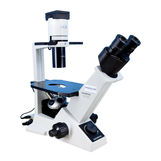
CKX31/CKX41 A. OUTLINE OF PRODUCT 1. Outline (1) CKX31: Inverted culture microscope with fixed observation tube (successor to CK30) CKX41: Inverted culture microscope with interchangeable observation tube (successor to CK40) Reflected light fluorescence attachment mountable (2) Target market and applications Tissue culture routine market represented by culture, growth, immunity and pharmacy. -
Page 5: Using Conditions
(4) Observation is possible in F.N.20 to 22. 3. Using conditions CKX31/CKX41 (1) Ambient temperature: Temperature: 0 - 40 degrees C(32-104 degrees F), Humidity: 30-90% (2) Range of combination: As indicated by the CKX41/CKX31 system chart. (3) Applicable objective 1) Phase contrast observation: Applicable slider IX2-SLP... -
Page 6: Specifications
CKX31/CKX41 A. OUTLINE OF PRODUCT (3) A intermediate attachment can not be attached. When U-EPA is used in CKX40 a peripheral light intensity becomes slightly insufficient in the following combinations. *Binocular observation in F.N.22 with U-TBI-3 and 4X (or10X) objective. -
Page 7: Dimensions
CKX31/CKX41 A. OUTLINE OF PRODUCT 5. Dimensions 1) CKX31 2 3 7.6 370.5 486.6 1) CKX41 237.6 370.5 515.5 UNIT: mm... -
Page 8: Ckx31/Ckx41 System Chart
CKX31/CKX41 A. OUTLINE OF PRODUCT 6. CKX31 / CKX41 system chart... -
Page 9: Inspection Standard
(1 graduation = 0.1mm) of the KN0048. * 1) Since the binocular section of CKX31 is the same as that of CK30, the procedure of optical axis adjustment is performed in the same manner as CK30. (Refer to the adjustment part of D-3 - D-14 in CK30/40 repair manual.) 2) Nesessary jigs are partially different because UIS optical system is adopted in CKX. - Page 10 Read the displacement between specimen center in KN0041 and the visual field center using the reticle scale (1 graduation = 0.1mm) of KN0048. * In parfocality adjusument, the washer (selection: 6 pcs. available) is used for CKX41 (same as CKX31).
- Page 11 CKX31/CKX41 B. INSPECTION STANDARD <CKX41> Part Item Standard Method Set the following jigs to the microscope frame Binocular Optical axis, CH3-BI45 repair manual and check the optical axis and exit pupil center. tube (Refer to E-2 - E-12 of exit pupil center referring the CH3-BI45 repair manual.
-
Page 12: Disassembly And Assembly Procedures
CKX31/CKX41 C. DISASSEMBLY AND ASSEMBLY PROCEDURES 1. CKX31 frame Change the position to adjust absolute optical axis. Screw mounting part : Adhesive ; OT1026 (b): Selection Parfocality adjustnent Inner screw threads : Grease ; OT2144 Inner screw threads : Grease ; OT2144 Screw it to (G). - Page 13 CKX31/CKX41 C. DISASSEMBLY AND ASSEMBLY PROCEDURES Parts name Screw Grease Adhesive Remark STAGE PART AB5X15SA, 4pcs. (*1) CK4 -ILL30 AB6X12SA, 4pcs. (*2) For disassembly, refer to C-15. COVER CUKSK3X8SA, 4pcs. (*3) COVER 3PUTB2X4SA, 1pc. (*4) Adjust absolute optical axis. AB3X14SA, 4pcs. (*5)
-
Page 14: Ckx41 Frame
CKX31/CKX41 C. DISASSEMBLY AND ASSEMBLY PROCEDURES 2. CKX41 frame Screw mounting part : Adhesive ; OT1026 Inner screw threads : Grease ; OT2144 Disassembly of Mount(g) Screw it to (H). - Page 15 CKX31/CKX41 C. DISASSEMBLY AND ASSEMBLY PROCEDURES Grease Adhesive Parts name Screw Remark INSERT PLATE AB5X15SA, 4pcs. (*1) STAGE PART AB6X12SA, 4pcs. (*2) For disassembly, refer to C-15. CK4 -ILL30 COVER CUKSK3X8SA, 2pcs. (*3) 3PUTB2X4SA, 1pc. (*4) COVER AB3X14SA, 4pcs. (*5)
-
Page 16: Binocular Tube Of Ckx31 Frame
CKX31/CKX41 C. DISASSEMBLY AND ASSEMBLY PROCEDURES 3. Binocular tube of CKX31 frame (screw for fixing eyepiece) Tension adjustment: light Double-sided Prism ass’y: pushing direction Adhesive heavy tape Grease ; OT3189 (screw for fixing eyepiece) Grease ; OT3189 Contacting surface only Grease ;... - Page 17 CKX31/CKX41 C. DISASSEMBLY AND ASSEMBLY PROCEDURES Parts name Screw Grease Adhesive Remark CUK3X6SA, 4pcs. (*1) BINOCULAR TUBE KNW3SA, 4pcs. (*2) COVER 3PUTB2X4SA, 3pcs. (*3) COVER 3PUTB2X4SA, 3pcs. (*4) Attach it with double coated INDICATOR PLATE adhesive tape. Refer to D-1.
-
Page 18: Binocular Tube (U-Cbi30-2) For Ckx41
CKX31/CKX41 C. DISASSEMBLY AND ASSEMBLY PROCEDURES 4. Binocular tube ( U-CBI30-2) for CKX41 Scale seal Anti-fungus agent Screw for fixing eyepiece Contacting surface Grease; OT3189 Tension adjustment: heavy Grease; OT3189 light Grease; OT3189 Grease; OT3189 Adhesive tape Screw for Double-sided fixing eyepiece Prism ass’y and inclined prism:... - Page 19 Same as the above PRISM ASS’Y CUK3X8SA, 2pcs. (*10) Tension: standard 5-15N TORQUE PLATE AWU3X4SA, 2pcs. (*11) (OT3223) Since the adjustment is the same as that of CKX31, refer to C-6. SPRING WASHER WASHER MOUNT OT3189 RING PRISM MOUNT-R OT3189...
-
Page 20: Coarse / Fine Focus Adjustment Knob
CKX31/CKX41 C. DISASSEMBLY AND ASSEMBLY PROCEDURES 5. Coarse / fine focus adjustment knob Double-sided Adhesive tape Foucusing guide unit(M): Grease; when assembling it, Check item: OT2008 push it in arrow directions. refer to B. inspection standard on B-2. Grease; OT2008 Adhesive;... - Page 21 CKX31/CKX41 C. DISASSEMBLY AND ASSEMBLY PROCEDURES Parts name Screw Remark Grease Adhesive PLATE ABS3X8SA, 2pcs. (*1) PLATE Rotating tension: FINE ADJ. KNOB Standard: 0.3N -1.2N(OT3225) FINE ADJ. KNOB OT2008 OT1378 Apply grease to the circumference ASS’Y of the shaft(a). Rotating tension: CWK3X6SA, 3pcs.
-
Page 22: Focusing Guide Unit
CKX31/CKX41 C. DISASSEMBLY AND ASSEMBLY PROCEDURES 6. Focusing guide unit Guide (D) * Arrange the rollers altenately on the upper side so that they face in same direction to lower side. Adjustment (guide mounting position) Working force: standard 0.2 - 0.5N (without play or tightness) Arrange the rollers alternately. - Page 23 CKX31/CKX41 C. DISASSEMBLY AND ASSEMBLY PROCEDURES Parts name Screw Remark Grease Adhesive Attach it with double coated COVER adhesive tape. COVER Fit the protrutions into the holes CUKK3X6SA, 1pc. (*1) of frame. Mount it while pushing it to front FOCUSING GUIDE AB4X14SA, 3pcs.
-
Page 24: Electrical Unit
CKX31/CKX41 C. DISASSEMBLY AND ASSEMBLY PROCEDURES 7. Electrical unit Voltage adjustment trimmers : VR21; minimum voltage VR23; maximum voltage *Refer to D-14. to CN2 VR21 (4 pcs.) (this part only) VR23 Rheostat ass’y base (this part only) (a): screws for fixing the bottom plate. - Page 25 CKX31/CKX41 C. DISASSEMBLY AND ASSEMBLY PROCEDURES Parts name Screw Remark Grease Adhesive ACU3X10SA, 1pc. (*1) KNOB CTK3X6SA, 4pcs. (*2) BOTTOM PLATE HWB3SA, 1pc. (*3) CUKS3X8SA, 4pcs. (*4) HWB3SA, 1pc. (*5) Connection to CN1 CABLE ASS’Y (output side connector) Connection to CN3 CABLE ASS’Y...
-
Page 26: Transmitted Illuminator
CKX31/CKX41 C. DISASSEMBLY AND ASSEMBLY PROCEDURES 8. Transmitted illuminator Double-sided Adhesive tape FROSTED Adhesive; OT1026 Double-sided Adhesive Grease; tape OT2010 *sliding surface on the bottom Adhesive; Grease; OT1026 OT2010 *sliding surface Adhesive; on the top OT1026 Adhesive; OT1026 C-15... - Page 27 CKX31/CKX41 C. DISASSEMBLY AND ASSEMBLY PROCEDURES Parts name Screw Remark Grease Adhesive AB6X12SA, 4pcs. (*1) AB4X10SA, 1pc. (*2) COVER Attach it with double coated adhesive tape. CORD BAND CORD HOLDER Attach it with double coated adhesive tape. FILTER FRAME LENS TUBE...
-
Page 28: Repair Procedure
CKX31/CKX41 D. REPAIR PROCEDURE 1. Overview of optical adjustment (1 ) Optical axis (CKX31) Cover-R <Fig.1> Cover-L 1) After removing the stage, peel off the seals and remove the screws (*1,*2). Screws: 3PUTB2X4SA 1pc. (*1), CUKSK3X8SA 4pcs.(*2) BI tube 2) Separate the cover-L and cover-R. - Page 29 Screw: CUKK3X6SA 4pcs. (*5) (4) Parfocality <CKX41> *In the same manner as CKX31, adjust the paforcality by inserting washer under the lens frame-1. (For adjustment procedure, refer to D-12.) <Left sleeve> Diopter ring (A) Helicoid ass’y (B)
-
Page 30: Adjustment Procedure (Ckx31
CKX31/CKX41 D. REPAIR PROCEDURE 2. Adjustment procedure (CKX31) Preparation for optical adjustment See D-4. Adjusting parfocality See D-5 to D-6. Jigs : See D-4 Adjusting revolving axis Procedure: See D-3 (3-2, 3-3) to D-7 in CK30/40 repair manual Jigs : See D-4... -
Page 31: Preparation For Optical Adjustment (Ckx31
CKX31/CKX41 D. REPAIR PROCEDURE 2-1 Preparation for optical adjustment (CKX31) KN0048 (with adapter-1) KN0029 FT36 KN0003 KN0041 PlanC10X SKN0003 Adjustment item Eyepiece(Jig) Objective(Jig) Jigs and tools 1) Standard eyepiece 1. Revolving axis 2) PlanC10X 3) Test plate : (right sleeve) concentric circles (KN0048;... -
Page 32: Checking Parfocality For Ckx31
CKX31/CKX41 D. REPAIR PROCEDURE 2-2 Checking parfocality for CKX31 Set the following jigs as illustrated below to check the parfocality. Necessary jigs : 1) Focusing telescope (FT-36 or U-FT) 2) Standard eyepiece (KN0048; Adapter-1) 3) Standard objective (KN0041) Stop in the position where the cross hairs in the KN0048 can be seen clearly. -
Page 33: Parfocality Adjustment For Ckx31
CKX31/CKX41 D. REPAIR PROCEDURE 2- 3 Parfocality adjustment for CKX31 Relay lens ass’y consists of three parts, lens frame-1(A), frame-2(B) and lens frame-3(C). (For the composition of lenes, refer to the Fig.1 and Fig.2.) Set the jigs to the microscope and check the parfocality. (Refer to D-5.) Adjustment procedure: (1) Remove the stage part, and take off the covers. - Page 34 CKX31/CKX41 D. REPAIR PROCEDURE Parfocality adjustment amount (CKX31: reference value) Unit: mm Washer selection < standard : 1.0 > Total Reading value Reading value washer (before adjustment) AB129900 AB130000 AB130200 AE092100 AE092200 AE092300 (after adjustment) thickness 0.05 1.75 0.03 1.70 0.06...
-
Page 35: Adjustment Procedure (Ckx41
CKX31/CKX41 D. REPAIR PROCEDURE 3. Adjustment procedure (CKX41) See D-9. Preparation for optical adjustment See D-10.(adjustment in binocular tube) Adjusting parfocality See D-11 to D-12. Jigs : See D-10. Adjusting revolving axis Procedure: See E-3 to E-6 in CH3-BI45 repair manual. -
Page 36: Preparation For Optical Adjustment (Ckx41
CKX31/CKX41 D. REPAIR PROCEDURE 3-1 Preparation for optical adjustment (CKX41) FT-36 KN0048 (with adapter-1) * For optical adjustment in binocular tube, KN0023 refer to D-10. KC2040 Adapter-2 BXKN001 KN0041 PlanC10X SKN0003 Adjustment item Eyepiece(Jig) Objective(Jig) Jigs and tools 1. Absolute optical axis... - Page 37 CKX31/CKX41 D. REPAIR PROCEDURE <Optical adjustment in binocular tube> FT-36 KN0048 (with adapter-1) KN0029 KN0003 KN0041 PlanC10X Adjustment item Eyepiece(Jig) Jigs and tools Objective(Jig) 1) Standard eyepiece 1. Revolving axis 2) PlanC10X 3) Test plate : (right sleeve) concentric circles (KN0048;...
-
Page 38: Checking Parfocality For Ckx41
CKX31/CKX41 D. REPAIR PROCEDURE 3-2 Checking parfocality for CKX41 Set the following jigs as illustrated below to check the parfocality. Necessary jigs : 1) Focusing telescope (FT-36 or U-FT) 2) Standard eyepiece (KN0048; Adapter-1 and Adapter-2) 3) 3mm ring adapter (KC2040) -
Page 39: Parfocality Adjustment For Ckx41
CKX31/CKX41 D. REPAIR PROCEDURE 3-3 Parfocality adjustment for CKX41 Relay lens ass’y consists of three parts, lens frame-1(A), lens frame-2(B) and lens frame(C). (For the composition of lenses, refer to the Fig.1 and Fig.2.) Set the jigs to the microscope and check the parfocality. (refer to D-11.) Adjustment procedure: (1) Remove the stage, and take off the covers. - Page 40 CKX31/CKX41 D. REPAIR PROCEDURE Parfocality adjustment amount (CKX41: reference value) Unit: mm Washer selection < standard : 0.7 > Total Reading value Reading value washer (before adjustment) AB129900 AB130000 AB130200 AE092100 AE092200 AE092300 (after adjustment) thickness 0.05 1.05 -0.03 1.05 -0.13...
-
Page 41: Electrical Unit
CKX31/CKX41 D. REPAIR PROCEDURE 4. Electrical Unit 4-1 CKX31/CKX41 connecting diagram Circuit board ass'y (AQ828900) U003 U001 U002 U004 E002 E003 E001 E002 E003 S001 Circuit board (DZ308400) U103 6V30W INPUT Halogen Lamp E005 E006 100-120/ 220-240VAC E004 50/60Hz E001: Ferrite core... -
Page 42: Jigs And Tools
CKX31/CKX41 E. JIGS AND TOOLS 1. List of jigs and tools Description Page BKN001 UIS standard observation tube B-2, D-9,11,12 FT36(or U-FT) Focusing telescope B-1,2,3, D-4,5,9,10,11 3mm ring adapter B-2, D-9,11 KC2040 Test plate (5/100mm concentric circles) B-1, 3, D-4,10... -
Page 43: Lubricants And Chemicals
CKX31/CKX41 F. LUBRICANTS AND CHEMICALS 1. List of greases Description Page OT2006 C-10 Grease (heavy) Grease (medium) OT2008 C-10 Grease (light) C-12,16 OT2010 C-10 Mo grease OT2012 Grease (light) OT2144 C-2,4 Silicone grease C-6,8 OT3189 2. List of adhesives Page...
Need help?
Do you have a question about the CKX31 and is the answer not in the manual?
Questions and answers