Table of Contents
Advertisement
Quick Links
Advertisement
Table of Contents

Related Manuals for Olympus CK40M FRAME


Summary of Contents for Olympus CK40M FRAME
- Page 1 COMPACT INVERTED METALLURGICAL MICROSCOPE CK40M FRAME REPAIR MANUAL OLYMPUS...
- Page 2 COMPACT INVERTED METALLURGICAL MICROSCOPE CK40M FRAME REPAIR MANUAL OLYMPUS All rights reserved, Reproduction in whole or in part without written permission is prohibited. (9G)
-
Page 3: Table Of Contents
3. Using conditions ------------------------------------------------------------------------- A-1 4. Specifications ---------------------------------------------------------------------------- A-3 5. Dimensions ------------------------------------------------------------------------------- A-4 B. DISASSEMBLY AND ASSEMBLY PROCEDURES 1. CK40M frame (1) ----------------------------------------------------------------------- B-1 2. CK40M frame (2) ----------------------------------------------------------------------- B-3 3. CK40M frame (3) ----------------------------------------------------------------------- B-5 4. CK4M-REH------------------------------------------------------------------------------ B-7 5. CK4-J ------------------------------------------------------------------------------------- B-9 6. -
Page 4: Outline Of Product
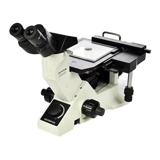
CK40M A. OUTLINE OF PRODUCT Outline Compact inverted metallurgical microscope, which is flexible to interchange observation tubes Target market, usage Industrial inspection market (Sample observation and inspection, and abrasive inspection at plants and iron works) External standards acquired • The product complies with UL and GS. The CE mark was self-declared. FCC is not applicable. - Page 5 CK40M A. OUTLINE OF PRODUCT • When CK40-MVR (mechanical stage) is mounted on the right side (seen from the operation knob side) of the plane stage, CK40M-MS (stage mirror) cannot be mounted on there. • When it is combined with CK40M-CP (stage plate), the observation range depends on the objective.
-
Page 6: Specifications
CK40M A. OUTLINE OF PRODUCT This model can be combined with the following observation tubes: CH3-BI, CH3-TR45, CK40-TBI Specifications Item Specifications Remarks • Revolving nosepiece vertical movement (Stage fixed type) Focus • Coaxial coarse/fine adjustment knobs (Coarse adjustment with torque adjustment mechanism) •... -
Page 7: Dimensions
CK40M A. OUTLINE OF PRODUCT Dimensions Unit: mm... -
Page 8: Disassembly And Assembly Procedures
CK40M B. DISASSEMBLY AND ASSEMBLY PROCEDURES CK40M frame (1) ‡ Š ˆ CK40M-MS ‚ ‰ ƒ … „ Coated • surface † Parts name Screw Grease Adhesive Remarks • SEAL (3 pcs.) ‚ CK4M-MA AB4X12SA (*1) 3 pcs. Adjustment (C-8, 9) ƒ... - Page 9 CK40M B. DISASSEMBLY AND ASSEMBLY PROCEDURES Reflection protector (AD378100) mounting position Reflection protector (AD378100) Longer Double-coated adhesive tape Place the reflection protector on Plate (AD377800) the plate and stick it, aligning the right and left widths of reflection protector to the center hole. Half mirror (LP148000) mounting position Set the positioning jig (CK40MKC01) on the half mirror mount.
-
Page 10: Ck40M Frame (3
CK40M B. DISASSEMBLY AND ASSEMBLY PROCEDURES CK40M frame (2) „ … • ƒ ‚ ˆ ‰ † ‡ Avoid disassembling parts †, ‡, and ˆ unless necessary. Note: When mounting the assembled parts of †, ‡, and ˆ to TR body …, screw this assembly in completely to the end (in case where these parts are disassembled). - Page 11 CK40M B. DISASSEMBLY AND ASSEMBLY PROCEDURES Prism (LP142600) mounting position M S Surface A CK40MKC02 TR body (AD064400) Prism (LP142600) Mount the prism positioning jig (CK40MKC02) on the TR body (and tighten it firmly). Set the prism against the jig. Determining this as the prism fixing position, apply silicone adhesive (OT1873) at least 15 mm on the both sides of the prism.
- Page 12 CK40M B. DISASSEMBLY AND ASSEMBLY PROCEDURES CK40M frame (3) „ ˆ ‰ ƒ … • Š Voltage selector switch Coated † surface ‡ ‚ Parts name Screw Grease Adhesive Remarks • KNOB ACU3X12SA (*1) 1 pc. ‚ CK4-BD100or200 CUKS3X8SA (*2) 4 pcs.
- Page 13 CK40M B. DISASSEMBLY AND ASSEMBLY PROCEDURES Mounting direction of voltage selector switch Voltage selector switch Mounting direction Gray (100 V) Brown (200 V) Make sure that the black cable is connected to the 100 V (220 V) side of the voltage selector switch. Black (100 V/200 V) Transformer ass’y 100/200...
-
Page 14: Ck4M-Reh
CK40M B. DISASSEMBLY AND ASSEMBLY PROCEDURES CK4M-REH ‚ ‰ Š ˆ „ … ƒ • † ‡ Parts name Screw Grease Adhesive Remarks • TUBE ‚ NOSEPIECE AB4X14SA (*1) 3 pcs. OT1131 Apply adhesive to the CUKSK2.6X6SA (*2) 4 pcs. circumference of screw thread. - Page 15 CK40M B. DISASSEMBLY AND ASSEMBLY PROCEDURES WIRE (2 pcs.) NOSEPIECE OT2010 Apply grease in the MOUNT groove to fit the wire SCREW RACK AB3X8SA (*5) 3 pcs. OT1838 Pushing direction (refer to the figure on previous page)
-
Page 16: Ck4-J
CK40M B. DISASSEMBLY AND ASSEMBLY PROCEDURES CK4-J ‚ „ … † • ˆ ‰ ‡ Š ƒ ‚ •... - Page 17 CK40M B. DISASSEMBLY AND ASSEMBLY PROCEDURES Parts name Screw Grease Adhesive Remarks • PLATE (2 pcs.) ‚ Apply adhesive to the screw FINE ADJ. KNOB ABS3X8SA (*1) 2 pcs. OT1131 thread. ƒ Apply grease to the shaft. FINE ADJ. KNOB OT2008 ASS’Y „...
-
Page 18: Ck4M-Ma
CK40M B. DISASSEMBLY AND ASSEMBLY PROCEDURES CK4M-MA • … Coated surface ‡ Š ‰ „ ˆ † Frosted ƒ ‚ B-11... - Page 19 CK40M B. DISASSEMBLY AND ASSEMBLY PROCEDURES Parts name Screw Grease Adhesive Remarks • COVER AB3X14SA (*1) 3 pcs. ‚ MAIN TUBE ANU4X6SA (*2) 3 pcs. ANU3X4SA (*3) 3 pcs. ƒ LENS TUBE AB3X45SA (*4) 3 pcs. „ INSULATION TUBE … SOCKET MOUNT †...
- Page 20 CK40M B. DISASSEMBLY AND ASSEMBLY PROCEDURES Diaphragm frame (AD377200) mounting position Diaphragm frame (AD377200) Mark position Assemble in the position where the tap of AB112800 is about 5 mm from the notch of AD377200. Notch position Diaphragm frame (AB112800) Diaphragm blade (AQ037400) Tap position Mark position...
- Page 21 CK40M B. DISASSEMBLY AND ASSEMBLY PROCEDURES Indicator plate (AD379400) mounting position M S Contacting the end of indicator plate on the rear surface and stick it with the double coated tape on the reverse side, aligning it to the outer side of filter tube.
-
Page 22: Repair Procedure
CK40M C. REPAIR PROCEDURE Adjustment procedure 2. Preparation for adjustment (Refer to C-2.) 3. Absolute optical axis adjustment (Refer to C-3.) 4. Stage parallelism adjustment (Refer to C-7.) 5. CK4M-MA illumination center adjustment (Refer to C-8.) 6. MA-AS center adjustment (Refer to C-10.) 7. -
Page 23: Preparation For Adjustment
CK40M C. REPAIR PROCEDURE Preparation for adjustment MS Standard eyepiece (KN0048, with Adapter-1) Centering telescope (KN0029) Standard tube (BKN0003) Mirror Stage insert plate Standard objective (KN0041) Objective (MDPlan5X) (MDPlan80X) Gauge for checking stage tilt alignment (SKN0003) Adjustment item Eyepiece (jig) Objective (jig) Jig and tool Absolute optical axis... -
Page 24: Absolute Optical Axis Adjustment
CK40M C. REPAIR PROCEDURE Absolute optical axis adjustment Set the following jigs as illustrated below to adjust the absolute optical axis. • Eyepiece------ KN0048: Standard eyepiece (with adapter-1) • Objective ----- KN0041: Standard objective • Other --------- BKN0003: Standard tube Standard eyepiece (KN0048, with... - Page 25 CK40M C. REPAIR PROCEDURE Adjusting the absolute optical axis Work Image seen through the standard eyepiece (1) Slightly loosen the four SCREWS • fixing the TR If the absolute optical axis is displaced, the cross hairs body ass’y (to the extent that the unit does not center of standard eyepiece is not located at the cross become loose.) center of the specimen in the standard objective.
- Page 26 CK40M C. REPAIR PROCEDURE (3) Firmly tighten the four SCREWS • fixing the TR Make sure that the adjusted position body ass’y. may not be changed. • •...
- Page 27 CK40M C. REPAIR PROCEDURE Checking the absolute optical axis The cross center of specimen in the standard objective should be within the shaded range on the reticle scale of standard eyepiece. 2 graduations Magnified view of the central part (The range within the shaded area is the standard.) If the cross center of specimen in the standard objective is not within the above range, return to “3.
-
Page 28: Stage Parallelism Adjustment
CK40M C. REPAIR PROCEDURE Stage parallelism adjustment Set the following jig as illustrated below to adjust the parallelism of the stage. • Mount the gauge (SKN0003) on the revolving nosepiece. • Use a 0.07 mm thickness gauge (OT1949). Gauge for checking stage tilt alignment (SKN0003) Stage mount Checking method... -
Page 29: Ck4M-Ma Illumination Center Adjustment
CK40M C. REPAIR PROCEDURE CK4M-MA illumination center adjustment Set the following jigs as illustrated below to adjust the CK4M-MA illumination center. • Eyepiece-----KN0029: Centering telescope • Other --------BKN0003: Standard tube, stage insert plate, mirror Centering telescope (KN0029) Standard tube (BKN0003) AB 5X15SA The mirror side Mirror... - Page 30 CK40M C. REPAIR PROCEDURE Adjusting CK4M-MA illumination center Temporarily fix the stage. (Screw: AB5X15SA 4 pcs.) Loosen the screws (ANU3X4SA 2pcs.) fixing the slider mount. Insert slide glass between the slider mount and the revolving nosepiece and fix the slider mount where it becomes flat. To look at the bulb filament, remove the frosted glass from the illuminator.
-
Page 31: Ma-As Center Adjustment
CK40M C. REPAIR PROCEDURE MA-AS center adjustment Set the following jigs as illustrated below to adjust the MA-AS center. • Eyepiece ------KN0048: Standard eyepiece (with adapter-1) KN0029: Centering telescope • Objective------MDPlan80X • Other ----------BKN0003: Standard tube, stage insert plate, mirror Standard eyepiece (KN0048, with Adapter-1) - Page 32 CK40M C. REPAIR PROCEDURE Adjusting AS center Fully open the aperture diaphragm (AS). Set the standard eyepiece and focus on the mirror surface. Take out the standard eyepiece and set the centering telescope. Look at the exit pupil of the objective through the centering telescope. At this time, the AS image may be slightly out of focus (it is acceptable in this adjustment).
-
Page 33: Parfocality Adjustment
CK40M C. REPAIR PROCEDURE Parfocality adjustment Set the following jigs as illustrated below to adjust the parfocality. • Eyepiece------ KN0048: Standard eyepiece (with adapter-1) • Objective ----- KN0041: Standard objective • Other --------- FT-36 or KN0025: focusing telescope (-1), BKN0003: Standard tube FT-36 Standard eyepiece... - Page 34 CK40M C. REPAIR PROCEDURE Checking parfocality Align the white scale with the red scale on KN0048. Using the focusing telescope, focus on the cross hairs in the KN0048. Turning the helicoid ring of the standard eyepiece, focus on the wave pattern of the specimen in the standard objective.
-
Page 35: Exit Pupil Center Check
CK40M C. REPAIR PROCEDURE Exit pupil center check Set the following jigs as illustrated below to check the exit pupil center. • Eyepiece------ KN0029: Centering telescope • Objective ----- MDPlan5X • Other --------- BKN0003: Standard tube Centering telescope (KN0029) Standard tube (BKN0003) MDPlan5X •... -
Page 36: Fine Focus Sensitivity Check
CK40M C. REPAIR PROCEDURE Fine focus sensitivity check Set one of following products as illustrated below to check the fine focus sensitivity. • Eyepiece--------------- WHK10X, WHK15X, NCWHK10X, GSWHK10X • Objective -------------- MDPlan5X, MDPlan10X, MDPlan20X, MDPlan40X, MDPlan50X, MDPlan80X MDAch10X, MDAch20X, MDAch50X •... -
Page 37: Jigs And Tools
CK40M D. JIGS AND TOOLS List of jigs and tools Description Page BKN0003 Standard tube C-3, 8, 10, 12, 14 CK40MKC01 Half mirror positioning jig CK40MKC02 Prism positioning jig (FT-36) Focusing telescope C-12 K2347 V-block KN0025 Focusing telescope (-1) C-12 KN0029 Centering telescope C-8, 10, 14... -
Page 38: Lubricants And Chemicals
CK40M E. LUBRICANTS AND CHEMICALS List of lubricants Description Page OT2006 Grease (heavy) B-10 OT2008 Grease (medium) B-3, 10, 12 OT2010 Grease (light) B-7, 8 OT2012 Molykote grease B-10 OT2142 Grease (light) B-12 OT2144 Grease (light) List of chemicals Description Page OT1131 Shellac...
Need help?
Do you have a question about the CK40M FRAME and is the answer not in the manual?
Questions and answers