Sign In
Upload
Download
Table of Contents
Contents
Add to my manuals
Delete from my manuals
Share
URL of this page:
HTML Link:
Bookmark this page
Add
Manual will be automatically added to "My Manuals"
Print this page
×
Bookmark added
×
Added to my manuals
Manuals
Brands
Owon Manuals
Multimeter
B35
User manual
Owon B35 User Manual
Digital multimeter
Hide thumbs
Also See for B35
:
User manual
(43 pages)
,
Manual
(29 pages)
1
2
3
Table Of Contents
4
5
6
7
8
9
10
11
12
13
14
15
16
17
18
19
20
21
22
23
24
25
26
27
28
29
30
31
32
page
of
32
Go
/
32
Contents
Table of Contents
Bookmarks
Table of Contents
Digital Multimeter
Table of Contents
1 Safety Information
Safety Considerations
Measurement Category
Safety Terms and Symbols
2 General Characteristics
3 Quick Start
General Inspection
Install the Batteries
Adjusting the Tilt Stand
Power on
Sleep Mode
Backlight Control
Selecting the Range
Multimeter in Brief
Front Panel
Rotary Switch
Keypad
Display Screen
Measurement Units
Input Terminals
4 Making Measurements
Measuring AC or DC Voltage
Measuring Resistance
Testing Diodes
Testing for Continuity
Measuring Capacitance
Measuring Frequency
Measuring Transistor
Measuring Temperature
Measuring DC or AC Current
5 Multimeter Features
Data Hold Mode
Capturing Max. and Min. Values
Making Relative Measurements
Buzzer Feature
6 Bluetooth Function - B35(T) Only
How to Connect
User Interface
Operations
7 Technical Specifications
8 Appendix
Appendix A: Enclosure
Appendix B: General Care and Cleaning
Appendix C: Fuse Replacement
Advertisement
Quick Links
1
Bluetooth Function - B35(T) Only
2
How to Connect
3
Technical Specifications
Download this manual
See also:
User Manual
,
Manual
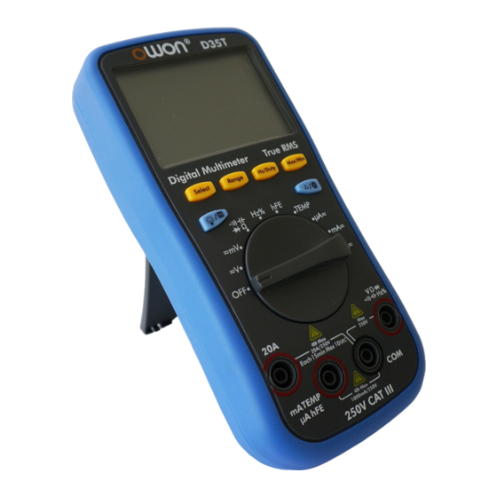
Digital Multimeter
User Manual
B35(T)
D35(T)
Note: "T" indicates true RMS (optional)
WWW.OWON.COM
Table of
Contents
Previous
Page
Next
Page
1
2
3
4
5
Advertisement
Table of Contents
Need help?
Do you have a question about the B35 and is the answer not in the manual?
Ask a question
Questions and answers
Related Manuals for Owon B35
Multimeter Owon B35 User Manual
Digital multimeter (43 pages)
Multimeter Owon B35 Manual
(29 pages)
Multimeter Owon B41T User Manual
Digital multimeter (43 pages)
Multimeter Owon B33T User Manual
(33 pages)
Multimeter Owon D35T User Manual
Digital multimeter (32 pages)
Multimeter Owon HDS series User Manual
Hds series handheld digital storage oscilloscope & multimeter (72 pages)
Multimeter Owon HDS-N series User Manual
Hds-n series handheld digital storage oscilloscope & multimeter (88 pages)
Multimeter Owon Lilliput HDS1022M-N Specifications
Hds-n and hds series 2 in 1 t&m instrument combine digital oscilloscope and multi-meter. (8 pages)
Multimeter Owon HDS2062M-N User Manual
Handheld digital storage oscilloscope & multimeter (74 pages)
Multimeter Owon OW18 Series User Manual
(53 pages)
Multimeter Owon XDM1241 User Manual
(43 pages)
Multimeter Owon XDM1041 Quick Manual
(18 pages)
Multimeter Owon XDM2041 Series User Manual
(46 pages)
Multimeter Owon HDS1022M-I User Manual
Handheld digital storage oscilloscope & multimeter (93 pages)
Multimeter Owon XDM1000 Series User Manual
(40 pages)
Multimeter Owon XDM1000 Series User Manual
(45 pages)
This manual is also suitable for:
D35t
D35
B35t
Table of Contents
Print
Rename the bookmark
Delete bookmark?
Delete from my manuals?
Login
Sign In
OR
Sign in with Facebook
Sign in with Google
Upload manual
Upload from disk
Upload from URL


Need help?
Do you have a question about the B35 and is the answer not in the manual?
Questions and answers