Table of Contents
Advertisement
Advertisement
Table of Contents

Related Manuals for Owon XDM2041 Series


Summary of Contents for Owon XDM2041 Series
- Page 1 XDM2041 Series Digital Multimeter User Manual www.owon.com.cn...
- Page 2 LILLIPUT Company. Fujian LILLIPUT Optoelectronics Technology Co., Ltd. No. 19, Heming Road Lantian Industrial Zone, Zhangzhou 363005 P.R. China Tel: +86-596-2130430 Fax: +86-596-2109272 Web: www.owon.com.cn E-mail: info@owon.com.cn...
- Page 3 OWON for warranty work may be new or reconditioned like new performance. All replaced parts, modules and products become the property of OWON. In order to obtain service under this warranty, customer must notify OWON of the defect before the expiration of the warranty period. Customer shall be responsible for packaging and shipping the defective product to the service center designated by OWON, and with a copy of customer proof of purchase.
-
Page 4: Table Of Contents
Table of Contents 1.Safety Information ....................1 Safety Terms and Symbols ....................1 General Safety Requirements ....................2 Measurement Limits ......................3 Main Input Terminals (HI Input and LO Input) Measurement Limits ............3 Current Input Terminal (I) Measurement Limits ..................3 Sense Terminals (HI Sense and LO Sense) Measurement Limits .............. - Page 5 dB/dBm ..............................27 Relative Value ............................28 Data Record Function ......................29 Manual Record ............................29 Auto Record ............................29 Port Configuration ......................31 Serial ............................... 31 Language ..............................31 Backlight ..............................31 Clock ............................... 31 Default ..............................31 4.Measurement Tutorial ..................... 33 Loading Errors (DC Voltage) ....................
-
Page 6: Safety Information
1.Safety Information 1. Safety Information Safety Terms and Symbols Safety Terms Terms in this Manual. The following terms may appear in this manual: Warning: Warning indicates the conditions or practices that could result in injury or loss of life. Caution: Caution indicates the conditions or practices that could result in damage to this product or other property. -
Page 7: General Safety Requirements
1.General Safety Requirements General Safety Requirements Before any operations, please read the following safety precautions to avoid any possible bodily injury and prevent this product or any other products connected from damage. In order to avoid any contingent danger, this product is only used within the range specified. -
Page 8: Measurement Limits
1.General Safety Requirements Measurement Limits The protection circuitry of the multimeter can prevent damage to the instrument and protect against the danger of electric shock, when the Measurement Limits are not exceeded. To ensure safe operation of the instrument, do not exceed the Measurement Limits shown on the front panel, it is defined as follows: The user-replaceable 10 A current-protection fuse is on the front panel. -
Page 9: Sense Terminals (Hi Sense And Lo Sense) Measurement Limits
1.General Safety Requirements same voltage as the LO Input terminal, unless a current protection fuse is open. Sense Terminals (HI Sense and LO Sense) Measurement Limits The HI and LO sense terminals are used for four-wire resistance measurements. The Measurement Limit from HI Sense to LO Input is 200 Vpk. The Measurement Limit from HI Sense to LO Sense is 200 Vpk. -
Page 10: Quick Start
Manual. You can check whether there is any loss of accessories with reference to this description. If it is found that there is any accessory lost or damaged, please get in touch with the distributor of OWON responsible for this service or the OWON's local offices. -
Page 11: Foot Stool Adjustment
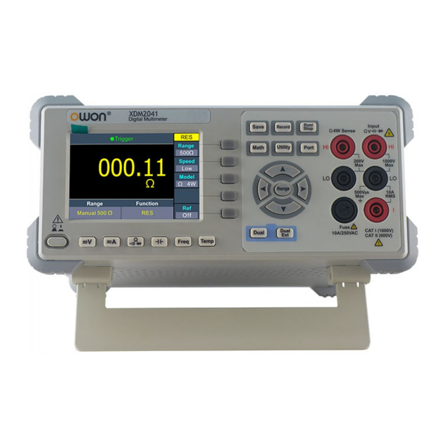
2.Quick Start 295 mm Foot Stool Adjustment Unfold the foot stool on the bottom of the multimeter. Front Panel Overview Figure 2-1 Front panel overview Item Name Description Display the user interface Menu selection Activate the corresponding menu Keys Operation Keys Save Collect data in manual record. - Page 12 2.Quick Start Run/Stop Start or stop auto trigger. When the trigger is stopped, the displayed data will be held. Math Perform math operations (Max/Min, dB/dBm) on the measurement results. Utility Set the auxiliary system function, including Language, Backlight, Clock, Default. Port Set Serial port.
-
Page 13: Rear Panel Overview
2.Quick Start Dual Press this key to display the function list on the right menu, select a function, if the function is supported, the reading will be displayed in the Vice Display. Dual Exit Press the key to exit dual display mode. Rear Panel Overview Figure 2-2 Rear panel overview Item Name... -
Page 14: User Interface
2.Quick Start User Interface Trigger Mode Status Icon Reading Operation Menus Unit Range Function Trigger Mode Status Icon Display Description Icon Description Trigger Auto trigger Auto record function is running Manual record Figure 2-3 User interface (Single display) Primary function reading Secondary function Primary function Figure 2-4 User interface (Dual display) -
Page 15: Power On
2.Quick Start Power On (1) Connect the instrument to the AC supply using the supplied power cord. Warning: To avoid electric shock, the instrument must be grounded properly. (2) Press down the power button at the front panel, the screen shows the boot screen. -
Page 16: Measurement Connections
2.Quick Start Measurement Connections After selecting the desired measurement function, please connect the signal (device) under test to the multimeter according to the method below. To avoid instrument damage, do not discretionarily switch the measurement function when measuring. DC Voltage Measurement AC Voltage Measurement DC Voltage AC Voltage... - Page 17 2.Quick Start Capacitance Measurement Frequency/Period Measurement Capacitance AC Signal Temperature Measurement Temp Transducer...
-
Page 18: Functions And Operations
3.Functions and Operations 3. Functions and Operations To Set The Range The instrument provides auto and manual range. In auto range, the multimeter selects a proper range automatically according to the input signal; in manual range, you can use the front panel key or menu softkey to set the range. The auto range can bring a lot of convenience for users while the manual range provides higher reading precision. -
Page 19: Measurement Speed
3.Functions and Operations Measurement Speed The instrument provides three types of measurement speed: "Low" speed is 4 reading/s; "Mid" speed is 16 reading/s; "High" speed is 65 reading/s. In DCV, ACV, DCI, ACI and 2-wire / 4-wire resistance measurements, the measurement speed is selectable. -
Page 20: Measuring Ac Voltage
3.Functions and Operations Measurement Speed”. 5. Set the relative value. Press the Rel softkey to turn on or off the relative operation. For relative operation, the multimeter subtracts the pre-specified value of REL operation from the actual measurement result and displays the result. See page 28, Relative Value. Measuring AC Voltage This section describes how to configure AC voltage measurements. -
Page 21: Measuring Dc Current
3.Functions and Operations the multimeter subtracts the pre-specified value of REL operation from the actual measurement result and displays the result. See page 28, Relative Value. Measuring DC Current This section describes how to configure DC current measurements. Operating Steps: 1. -
Page 22: Measuring Ac Current
3.Functions and Operations Measuring AC Current This section describes how to configure AC current measurements. Operating Steps: 1. Enable the ACI measurement. Press on the front panel, press it again to enter ACI measurement mode. 2. Connect the test lead. AC Current 3. -
Page 23: Measuring Resistance
3.Functions and Operations Measuring Resistance This section describes how to configure 2-wire and 4-wire resistance measurements. The multimeter provides 2-wire and 4-wire resistance measurements. When the measured resistance is lower than 100 kΩ, the 4-wire resistance measurement is recommended to reduce the measurement error caused by test lead resistance and contact resistance between the probe and the testing point, because these two resistances can not be ignored any more, compared to the measured resistance. -
Page 24: Continuity Test
3.Functions and Operations 4-wire Resistance 3. Set the range. Press the Range softkey to set the range. Auto range automatically selects the range for the measurement based on the input. Note: 1000 V input protection is available in all ranges. ... -
Page 25: Diode Test
3.Functions and Operations 2. Connect the test lead. Open or Closed Circuit 3. Set the beeper. Press the Beeper softkey to enable or disable the beeper. When the beeper is enabled, the reading is below 30 Ω, the multimeter will beep continuously. 4. -
Page 26: Measuring Capacitance
3.Functions and Operations 2. Connect the test lead. Forward Bias 3. Set the beeper. Press the Beeper softkey to enable or disable the beeper. When the beeper is enabled, the diode is connected, the multimeter will beep continuously. 4. Diode measurements behave as follows: Forward pressure Display and beep drop of diode... -
Page 27: Measuring Frequency And Period
3.Functions and Operations 2. Connect the test lead. Capacitance Tip: Please short contact the two feet of an electrolytic capacitor by using a test lead before measuring the electrolytic capacitor. 3. Set the range. Press the Range softkey to set the range. Auto range automatically selects the range for the measurement based on the input. -
Page 28: Measuring Temperature
3.Functions and Operations Press on the front, in the right menu, press the model soft key to switch and select Freq/Period measurement 2. Connect the test lead. AC Signal 3. Note Frequency range: 20 Hz to 60 MHz. 750 V input protection is available in all ranges. ... - Page 29 3.Functions and Operations Operating Steps: 1. Enable the temperature measurement. Press on the front panel to enter temperature measurement mode. 2. Connect the test lead. Temp Transducer 3. Set the sensor configuration file. Press the Load softkey, choose KITS90 or PT100. 4.
-
Page 30: Dual Display
3.Functions and Operations Dual Display Using dual display function, you can view the readings of two measurement functions simultaneously. Primary function reading Secondary function Primary function Figure 3-1 Dual Display Operating Steps: 1. Press one of the measurement function keys to turn on the primary measurement function. -
Page 31: Data Hold
3.Functions and Operations When the dual display is enabled, manual record function can save both of the primary and secondary readings, auto record function can only save the primary reading. Data Hold Data hold keeps the current reading on the display. (1) Press the Run/Stop panel key to Stop the trigger, and the current reading is kept on the display screen. -
Page 32: Math
3.Functions and Operations Math The multimeter provides these math functions: Max/Min, dB/dBm and relative. Only one operation can be enabled in the Max/Min, dB/dBm, or relative operation. Max/Min The Max/Min operation is used to calculate the max, min and average of the readings during the measurement period Press the front panel key, press the Max/Min softkey, press the Static softkey to... -
Page 33: Relative Value
3.Functions and Operations dB = 10 x Log ( reading / reference resistance / 1 mW) - dB preset Press the Ref R softkey to select the reference resistance. The value may be 50(default), 75, 93, 110, 124, 125, 135, 150, 250, 300, 500, 600, 800, 900, 1000, 1200, or 8000 Ω. Press the dB Ref Value softkey to select the relative value. -
Page 34: Data Record Function
3.Functions and Operations Data Record Function Data record function includes manual record and auto record. You can use any or both functions to record the data. Manual and automatic records share a table of data stored in internal storage.The maximum number of recorded points is 1000.After collecting the data, it can be exported to the computer. - Page 35 3.Functions and Operations 1 to 1000. Press the Interval softkey to specify the time interval between readings. The range is 15 ms to 9999.999 s. 2. Record data: Press the Start softkey to start auto record. The icon will show up on the top of the display.
-
Page 36: Port Configuration
3.Functions and Operations Port Configuration You can configure the port parameters in port configuration. Serial Press the front panel key, press the Serial softkey to access the serial port setting menu. Press the Baud softkey to select the desired baud rate from 2400, 4800, 9600, 19200, 38400, 57600 or 115200. - Page 37 3.Functions and Operations Type Item Value Baud 115200 Data bits Port Odd-Even None Stop bit Utility BLight 100% dB/dBm Off/On Function 50Ω Math Rel R 0Ω Db Rel Max/Min Static Auto Clear Manual Clear Record Point Interval Aoto On/Off Run/Stop Beeper 50Ω...
-
Page 38: Measurement Tutorial
4.Measurement Tutorial 4. Measurement Tutorial Loading Errors (DC Voltage) Measurement loading errors occur when the resistance of the DUT(Device-Under-Test) is an appreciable percentage of the multimeter's input resistance, as shown below. Ideal Meter = ideal DUT voltage = DUT source resistance = multimeter input resistance ×... -
Page 39: True Rms Ac Measurements
4.Measurement Tutorial True RMS AC Measurements The AC measurement of the multimeter has true RMS response. Power dissipated in a resistor is proportional to the square of an applied voltage, independent of the wave shape of the signal. This multimeter accurately measures true rms voltage or current, as long as the wave shape contains negligible energy above the meter’s effective bandwidth. -
Page 40: Loading Errors (Ac Voltage)
4.Measurement Tutorial Loading Errors (AC Voltage) In the AC voltage function, the input impedance of the multimeter appears as a 1 MΩ resistance in parallel with 100 pF of capacitance. The cabling that you use to connect signals to the multimeter also adds capacitance and loading. The table below shows the multimeter's approximate input resistance at various frequencies. -
Page 41: Crest Factor Errors (Non-Sinusoidal Inputs)
4.Measurement Tutorial Crest Factor Errors (non-sinusoidal inputs) A common misconception is that because an AC multimeter is true RMS, its sine wave accuracy specifications apply to all waveforms. Actually, the shape of the input signal dramatically affects measurement accuracy. A common way to describe signal wave shapes is “crest factor”. -
Page 42: Troubleshooting
4) Check whether the DCI measurement function is used to measure AC current. If you encounter other problems, try to reset the settings or restart the instrument. If it still can not work properly, please contact OWON for our service, and provide your device information. (Press the front panel... -
Page 43: Technical Specifications
6.Technical Specifications 6. Technical Specifications Function Range Resolution Accuracy: ± (% of reading + LSB) 50.000 mV 0.001 mV 0.1% + 10 500.00 mV 0.01 mV 0.025% + 5 5.0000 V 0.0001 V 0.025% + 5 DC Voltage 50.000 V 0.001 V 0.03% + 5 500.00 V... - Page 44 6.Technical Specifications General Specifications Display Screen 3.7-inch TFT LCD with resolution 480*320 Full accuracy from 0℃ to 50℃, 80% RH and 40℃, non condensing Operating Environment Storage Temperature: -20℃ to 70℃ Electromagnetic Conforming to EMC (2004/108/EC) and EN 61326-1:2013 compatibility Safety Conforming to EN 61010-1:2010 and low voltage instructions (2006/95/EC) Remote Interface...
-
Page 45: Appendix
7.Appendix 7. Appendix Appendix A: Enclosure Standard Accessories (subject to final delivery): Spare Fuses Power Cord Test lead Crocodile clip Quick Guide 1A, 250 VAC Appendix B: General Care and Cleaning General Care Do not store or leave the instrument where the liquid crystal display will be exposed to direct sunlight for long periods of time. - Page 46 7.Appendix Warning: Disconnect the line cord at the rear panel and remove all test leads connected to the instrument before replacing the line fuse. Failure to do so could expose the operator to hazardous voltages that could result in personal injury or death. Use only the correct fuse type.
Need help?
Do you have a question about the XDM2041 Series and is the answer not in the manual?
Questions and answers