
Related Manuals for Duplo DPB-500


Summary of Contents for Duplo DPB-500
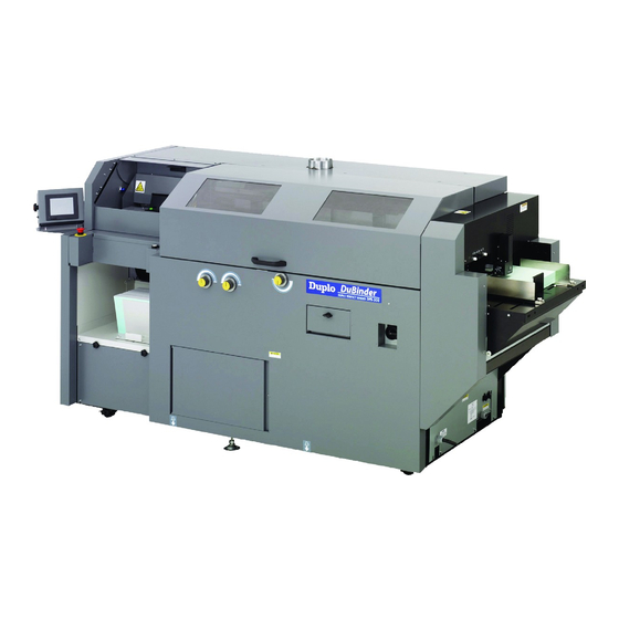
- Page 1 INSTRUCTION MANUAL Perfect Binder DuBinder DPB-500 Be sure to read this manual prior to use. Please leave this manual at the site of use for easy reference.
- Page 2 DECLARATION OF CONFORMITY DUPLO CORPORATION, located at 1-6, Oyama 4-chome, Sagamihara-shi, Kanagawa-ken 229-1180, Japan, declares that the following product, • Name of product : Binder • Model : DPB-500 complies with the provisions defined by the regulations listed below. • Regulation...
- Page 3 Disposal of Old Electrical & Electronic Equipment Eliminación de residuos de aparatos eléctricos y electrónicos This symbol (the symbol of the crossed out wheeled bin) indicates that in European countries this product Este símbolo (un cubo de basura tachado) indica should not be disposed of as household waste.
- Page 4 Note: This symbol mark is for EU countries only. Nota: questo contrassegno interessa soltanto i Paesi UE This symbol mark is according to the directive 2006/66/ Questo contrassegno è conforme alla direttiva EC Article 20 Information for end-users and Annex II. 2006/66/CE Articolo 20 Informazioni per gli utenti finali This symbol means that batteries and accumulators, at e Appendice II.
- Page 5 Note: This equipment has been tested and found to comply with the limits for a Class A digital device, pursuant to Part 15 of the FCC Rules. These limits are designed to provide reasonable protection against harmful interference when the equipment is operated in a commercial environment. This equipment generates, uses, and can radiate radio frequency energy and, if not installed and used in accordance with the instruction manual, may cause harmful interference to radio communications.
- Page 6 Introduction Thank you for purchasing a Duplo product. Be sure to read this manual prior to using the product. After reading, leave the manual at the site of use for easy reference whenever questions related to the product arise in the future.
-
Page 7: Power Supply
Safety Precautions Safety Precautions In this manual, operations and handling of the unit which are hazardous are described using the following marks to prevent personal injury or property damage to the user and others. Ignoring this mark could result in the possibility of serious injury or even death. - Page 8 Safety Precautions Operating Environment Operate this unit in the following environment. ● where the temperature range is between 5 and 35°C/41 and 95°F (-10 to +50°C/ 14 to 122°F) in storage) ● where the humidity range is between 10 and 85% RH (10 to 90% RH in storage, however no condensation) ●...
-
Page 9: Maintenance / Others
Safety Precautions Maintenance / Others Do not damage the power cord or power plug. Do not scratch, alter, bend, twist, pull or place heavy objects on the power cord or power plug. This could result in damage, a fire or an electrical shock. Do not touch the power switch with wet hands. -
Page 10: Hot Melt Glue
Safety Precautions Hot Melt Glue Because the hot melt glue is combustible, do not put the glue close to fire. It may cause a burn injury or fire. When you handle the hot melt glue, make sure that you wear protection gloves, long-sleeved clothes, eye protectors to prevent burn injuries. -
Page 11: Warning / Caution Labels
Safety Precautions WARNING / CAUTION Labels "WARNING" and "CAUTION" labels are pasted on the machine to ensure user safety. Do not remove or change them. When the labels become dirty or are lost, be sure to contact your dealer for a new one. WARNING Do not put hands inside during operation. - Page 12 Safety Precautions Details on Warning and Caution Label Label Explanation Do not touch the milling blade and roughening blade during machine operation. This may cause you severe injury. High voltage of electricity supplied to the glue tank may cause an electric shock. Be careful. Because the touch current is high, make sure that a ground connection is provided before connecting the power cord.
-
Page 13: Table Of Contents
Contents Safety Precautions Chapter 2 Safety Precautions ........i Power Supply ............i PREPARING FOR Operating Environment ........ii Maintenance / Others .........iii OPERATION Hot Melt Glue .............iv WARNING / CAUTION Labels ......v 1. Turning On the Power ......2-2 2. Preparing Hot Melt Glue ....2-3 Chapter 1 3. - Page 14 Safety Precautions Chapter 4 Chapter 5 FINE-ADJUSTMENT AND CLEANING THE UNIT OPTION SETTING 1. Cleaning Each Section .....5-2 1-1. Cleaning the Suction Belt ...... 5-2 1. Fine adjusting Each Part ....4-2 1-2. Cleaning the Level Plate ....... 5-3 1-1. Setting the Paper Feed Guide ....4-2 1-3.
-
Page 15: Before Operation
Chapter 1 BEFORE OPERATION... -
Page 16: Features
1. Features CHAPTER 1 BEFORE OPERATION This machine enables you to make a book with or without a cover. (1) With a cover Glue is applied to the side and spine of a book block, then a cover is applied to the pasted area. Cover Book block (2) Without a cover (Pad binding) -
Page 17: Workflow
2. Workflow CHAPTER 1 BEFORE OPERATION Chapter 2 “1. Turning on the Power” ( p.2-2) 1 Turn on the power 2 Prepare for hot melt glue Chapter 2 “2.Preparing Hot Melt Glue” ( p.2-3) 3 Prepare each section Chapter 2 “3. Preparing Each Section” ( p.2-6) Chapter 2 “4. -
Page 18: Names And Functions
3. Names and Functions CHAPTER 1 BEFORE OPERATION 3-1. External Parts Fume Exhaust Opening Jam Removing Knob When a paper jam occurs Exhausts steam from inside the Main Cover machine. during the transportation of Prevents the user from a cover, rotate this knob to touching inside of the move the feed roller and machine during operation. -
Page 19: Milling Section
CHAPTER 1 BEFORE OPERATION 3-2. Milling Section Milling Guide This guide prevents paper chips from scattering. The guide moves automatically according to the thickness of the book block. Milling Adjustment Label Refer to the label when adjusting the height of the level plate using the milling adjustment bar. -
Page 20: Glue Tank Section
CHAPTER 1 BEFORE OPERATION 3-3. Glue Tank Section Side Glue Roller Adjustment (non-operator’ s side) Adjusts the position of the side glue roller. Side Glue Meter Side Glue Roller Side Glue Meter Adjustment (non-operator’ s (non-operator’ s side) (non-operator’ s side) side) Adjusts the side glue Adjusts the position of the... -
Page 21: Nipping Section
CHAPTER 1 BEFORE OPERATION 3-4. Nipping Section Nipping Skewing Adjustment Station Nips the cover transported from the paper Skewing Adjustment Label feed tray to Adjusts the position of the form a spine. cover and the book block so that they are parallel to each Cover Stopper other. -
Page 22: Scoring Section
CHAPTER 1 BEFORE OPERATION 3-5. Scoring Section Primary Feed Roller Pressure Adjustment Scoring Depth Adjustment Adjusts the pressure of the Adjusts the depth of a score feed roller. applied to a cover. Secondary Feed Roller Pressure Adjustment Adjusts the pressure of the feed roller. -
Page 23: Feed Section
CHAPTER 1 BEFORE OPERATION 3-6. Feed Section Feeder Stack Height Sensor Feeds covers automatically. Adjustment Separator Select 1 or 2 to decide the Prevents double-feed of stop position of the cover covers. according to the thickness of the cover. Error Release Button When the paper feed Suction Belt tray has exceeded the... -
Page 24: Delivery Section
CHAPTER 1 BEFORE OPERATION 3-7. Delivery Section Book Exit Damper Serves as a cushion for the booklets delivered from the exit. Movable Stacker Aligns the finished booklets. Book Exit Damper Knob Screw Stacker Stopper Adjustment Lever Used to secure the Supports the delivered booklets Adjusts the angle of the book stacker stopper to the... -
Page 25: Screen Descriptions
4. Screen Descriptions CHAPTER 1 BEFORE OPERATION 4-1. Settings Screen for Binding After you turn the power on, the main menu screen appears on the panel. You can set the details of the binding process on this menu. Press other tabs on the screen to switch to other menus. Press the setting button to set up a binding process. -
Page 26: Motion Check Screen
CHAPTER 1 BEFORE OPERATION 4-3. Motion Check Screen Press the motion check tab to discharge finished booklets or jammed paper, to change the level of the paper feed tray, or to move the clamp. Refer to Chapter 4 "Fine-adjustment and Option Setting" "2.Using Motion Check" ( p.4-13) for de- tails. -
Page 27: Option Setting Screen
CHAPTER 1 BEFORE OPERATION 4-4. Option Setting Screen Press the option tab to select optional menus. Press the next or previous button to change the screen. Refer to Chapter 4 "Fine-adjustment and Option Setting" "3.Setting the Options" ( p.4-15) for details. Nipping Transparent Cover Delay Time... -
Page 28: Accessories
5. Accessories CHAPTER 1 BEFORE OPERATION Supplied (quantity) [10] [11] [12] [13] [14] [15] [16] Name Qty. Explanation [1] Guide Used when a cover does not go to the nipper guides smoothly because of a curled edge. [2] Small Cover Guide L Holds the tail edge of a small cover when feeding it to the machine. - Page 29 CHAPTER 1 BEFORE OPERATION Name Qty. Explanation [4] Stabilizer Plate Lite Weight Used when covers flaps fanned by separating air. Cover [5] Small Cover Guide Attached to the suction part when feeding a small cover. [6] Small Cover Feed Belt Attached to the suction part when feeding a small Accessory cover.
- Page 30 6. Wing Scoring (Optional) CHAPTER 1 BEFORE OPERATION [1] Wing Scoring (1) ------Used when applying a wing score to a cover. [2] Wrench (opposite side distance 2 mm) (1) ------Used to attach the wing scoring to the ma- chine. Chapter 3 "Starting Binding Operation" "8.Using Wing Scoring" ( p.3-25) 1-16...
-
Page 31: Precautions On Hot Melt Glue
7. Precautions on Hot Melt Glue CHAPTER 1 BEFORE OPERATION a. Precautions Before you use the hot melt glue, read "Hot Melt Glue" in "Safety Precautions" ( p.iv). Also, read carefully the handling precautions supplied with hot melt glue you are going to use. 1) When you handle the hot melt glue, make sure that you wear protection gloves, long-sleeved clothes, eye protectors to prevent burn injuries. -
Page 32: Cautions For Handling
8. Cautions for Handling CHAPTER 1 BEFORE OPERATION 1) Do not put your hand inside the machine during machine operation. This may cause you severe injury. 2) Do not touch blades (milling blade and roughening blade) during machine operation. This may cause you severe injury. -
Page 33: Emergency Stop
9. Emergency Stop CHAPTER 1 BEFORE OPERATION This machine is equipped with the emergency stop functions for the safety of an operator. When you need to stop the machine for emergency, press the emergency stop button. Turning the button to the right will release the emergency stop. The machine will also stop automatically when the main cover is opened or the light between the safety sensors is interrupted. -
Page 34: Paper Size
10. Paper Size CHAPTER 1 BEFORE OPERATION 10-1. Cover and Book Block Size This machine can handle a cover and book block of the following sizes. Book block length: 120 to 360 mm (4.72 to 14.17 inches) Book block thickness: 1 to 51 mm (0.04 to 2.01 inches) Book block height: 120 to 320 mm (4.72 to 12.6 inches) -
Page 35: Using Single-Folded Or Double-Folded Paper
CHAPTER 1 BEFORE OPERATION 10-3. Using Single-folded or Double-folded Paper You can use single-folded or double folded paper for a book block. The book block thickness of the folded side (spine) should be 50 mm (1.97 inches) or less when you place the book block on a flat surface. - Page 36 Memo CHAPTER 1 BEFORE OPERATION 1-22...
-
Page 37: Preparing For Operation
Chapter 2 PREPARING FOR OPERATION... -
Page 38: Turning On The Power
1. Turning On the Power CHAPTER 2 PREPARING FOR OPERATION Turn the power switch to the right to turn on the power of the machine. Power switch The hot melt glue in the glue tank will be ready for binding in about 30 minutes at earliest after you turn on the power. -
Page 39: Preparing Hot Melt Glue
2. Preparing Hot Melt Glue CHAPTER 2 PREPARING FOR OPERATION Glue Tank Temperature Button Press the glue tank temperature button. 2007-04-05 10:35 The temperature graph will be displayed. ● Check the melt temperature of the hot glue. The temperature of the glue tank is set at 150°C/302°F by default. - Page 40 CHAPTER 2 PREPARING FOR OPERATION Press the glue supply button. The side glue rollers will open to the maximum. If the hot melt glue temperature has not reached a temperature that is 20°C/68°F lower than the set temperature, the side glue rollers will not move. Glue Supply Button Add hot melt glue in the glue tank.
- Page 41 CHAPTER 2 PREPARING FOR OPERATION Close the main cover. ● Be careful not to get your hand caught when you close the main cover. ● When the main cover is open, the heater will be turned OFF automatically. Make sure that you close the main cover during heating.
-
Page 42: Preparing Each Section
3. Preparing Each Section CHAPTER 2 PREPARING FOR OPERATION 3-1. Level Plate To change the milling depth, adjust the height of the level plate. The milling operation jags a spine for better penetration of the glue. When milling depth is set to 0, a milling function is disabled and only notches by the roughening blade are applied to the spine, resulting in poor adhesivity. -
Page 43: Glue Tank
CHAPTER 2 PREPARING FOR OPERATION Milling adjustment bar Pull out the milling adjustment bar from the hole and put it back to its original place. 3-2. Glue Tank The position of the side glue rollers need to be changed depending on whether binding a book block with a cover or without a cover. -
Page 44: Nipping Section
CHAPTER 2 PREPARING FOR OPERATION You can turn the side glue roller adjustment within the range of 60°. When binding a book block without a cover, turn the adjustment 60° to the non- Side glue roller operator's side from the base position adjustment to move the side glue rollers to the non- operator's side. -
Page 45: Replacing The Receiving Tray With The Stacker Stopper
CHAPTER 2 PREPARING FOR OPERATION 3-4. Replacing the Receiving Tray with the Stacker Stopper You can use the stacker stopper for the booklet size of A5, B5, A4 and legal size or for the booklet with a height of 148 to 216 mm (5.83 to 8.50 inches). To replace the receiving tray with the stacker stopper, follow the procedures below. -
Page 46: Replacing The Stacker Stopper With The Receiving Tray
CHAPTER 2 PREPARING FOR OPERATION Secure the stacker stopper to the machine using the supplied knob screws (4). Stacker stopper When both a book block and cover is thin, the booklet may hit the movable stacker and be curled up. Use the receiving tray when the booklet is limp. - Page 47 CHAPTER 2 PREPARING FOR OPERATION Check that the movable stacker has been pushed backward (non- operator's side). Movable stacker Check that the book exit damper adjustment lever is set to "0." Book exit damper adjustment Stacker side guide Move the stacker side guide to the left side.
-
Page 48: Entering Job Information
4. Entering Job Information CHAPTER 2 PREPARING FOR OPERATION You can make the following settings on the main menu screen. 2007-04-05 10:40 1. Cover (With a cover/Without a cover) 2. Double feed detection (ON/OFF) 3. Book block size Setting 4. Cover size Button 5. - Page 49 CHAPTER 2 PREPARING FOR OPERATION Select whether to apply nipping to the book block using the nipping ON/ Nipping OFF button. ON/OFF button Nipping (ON) Nipping (OFF) Next Button When nipping is ON, the nipping station will go up during operation. Press the next button to go to "4-3.
-
Page 50: Setting Double Feed Detection For Cover
CHAPTER 2 PREPARING FOR OPERATION 4-2. Setting Double Feed Detection for Cover To make the machine detect double feed, decide and input the detection value. Change the double feed detection settings when detection error occurs frequently at the default setting (standard value). Press to select the LED luminescence amount. - Page 51 CHAPTER 2 PREPARING FOR OPERATION Press to select the starting point of the double feed detection. The starting point is a distance from the leading edge of the cover. Setting range: 20.0 mm (0.79 inch) to cover length minus 40.0 mm (1.57 inches) (standard value: 40.0 mm (1.57 inches)) Example 28.0...
-
Page 52: Setting Book Block Size
CHAPTER 2 PREPARING FOR OPERATION 4-3. Setting Book Block Size Select whether to change a book block thickness for each process. Variable mode Normal mode Normal: The thickness of book blocks is same for each process Variable: The thickness of book blocks varies for each process. - Page 53 CHAPTER 2 PREPARING FOR OPERATION Input value Numeric Keypad Input the book block length using the numeric keypad. Setting range: 120 to 360 mm (4.72 to 297. 0 14.17 inches) Book block Clear Button Book block length To clear the input value, press the clear button. Press the return button to confirm the value.
-
Page 54: Setting The Cover Size
CHAPTER 2 PREPARING FOR OPERATION 4-4. Setting the Cover Size Standard Size Cover Width Button Select Button Press the cover width button for specifying a cover width and the cover length button for specifying the cover length. The screen to input the value will appear. Cover Length Button If you use a standard-sized cover, press the... -
Page 55: Cover Base Spine Position
CHAPTER 2 PREPARING FOR OPERATION Press the return button to confirm the settings. You will go to "4-5. Cover Base Spine Position" ( p.2-19). To cancel the selection and return to the screen shown in step 1, press the cancel button. - Page 56 CHAPTER 2 PREPARING FOR OPERATION For side base Input the length between the scoring position and cover edge using the 190. 0 numeric keypad. The range you can input will be displayed Clear on the lower right of the screen. Press the Button cancel button or clear button, then input an Return Button...
-
Page 57: Checking And Saving Settings
CHAPTER 2 PREPARING FOR OPERATION For center base Input “0” using the numeric keypad and press the return button. Return button The base spine position button will be displayed as shown in the figure. The icon means that the scoring base line will align with the book block center line when you perform the size change in a later step. - Page 58 CHAPTER 2 PREPARING FOR OPERATION Memory No. Press to select the destination to save the settings. The number of memories is 20 and all of them contains the same setting data by default. Book block length: 297.0 mm (11.69 inches) Book block thickness: variable Cover (with or without a cover): With a cover Book block width: 420.0 mm (16.54 inches)
-
Page 59: Starting Binding Operation
Chapter 3 STARTING BINDING OPERATION... -
Page 60: Placing A Book Block
1. Placing a Book Block CHAPTER 3 STARTING BINDING OPERATION When binding with a cover: Follow the procedures below. When binding without a cover: After completing the step 2, go to "3. Starting Binding" ( p.3-14). Book block Place the book block in the clamp. Be sure to press the book block against the right edge of the clamp. - Page 61 CHAPTER 3 STARTING BINDING OPERATION Screw When the book block is thin and large: When the book block is thin and large, attach the supplied clamp guide to prevent the book block from bending over. Secure the clamp guide to the clamp using the screws attached to the clamp.
- Page 62 CHAPTER 3 STARTING BINDING OPERATION To cancel the size change, press the size change cancel button. The test feed button above the paper feed tray has a test feed function. If you press this button when the Movable clamp button movable clamp button icon is displayed on the main menu screen, a test feed will start.
- Page 63 CHAPTER 3 STARTING BINDING OPERATION Taking out the book block set in the clamp after size change After a size change, you cannot take out the book block from the clamp because 2007-04-05 10:50 it is firmly held in the clamp. To take out the book block, press the movable clamp button on the main menu.
-
Page 64: Test-Feeding A Cover
2. Test-Feeding a Cover CHAPTER 3 STARTING BINDING OPERATION Cover Load covers on the paper feed tray and press the back stopper against the covers. Paper feed tray Back stopper Cover Feed guide Feed guide Loosen the cover feeder skewing adjustments and turn the axes until the feed guides align with the covers. - Page 65 CHAPTER 3 STARTING BINDING OPERATION When selecting a center base, check the position of the cover attached to the book block, then fine adjust each part. You can also make the adjustments using the fine-adjustment screen. Refer to Chapter 4 "Fine-adjustment and Option Setting"...
- Page 66 CHAPTER 3 STARTING BINDING OPERATION Turn the adjustment little by little checking the feeding conditions. Test feed button Press the test feed button to feed a cover. The cover will be sent to the nipping section. Make sure that you move the cover stopper to the position for the largest paper size before you press the test feed button.
- Page 67 CHAPTER 3 STARTING BINDING OPERATION Check the scoring condition. Scoring depth adjustment Primary feed roller pressure adjustment Secondary feed roller pressure adjustment Scoring becomes deeper Base position Scoring depth adjustment axis axis To adjust the scoring depth, loosen the knob on the right and left scoring depth axis adjustments and turn each axis to the right.
- Page 68 CHAPTER 3 STARTING BINDING OPERATION When the cover is skewed. Primary feed roller pressure Base position Adjustment adjustment Leave the adjustment in its original position in normal times. However when the cover is skewed, move the position of the adjustment. The higher the position is, the stronger the pressure is.
- Page 69 CHAPTER 3 STARTING BINDING OPERATION Nipper guide adjustment . Press the tail edge of the cover Knob screw Positioning finger adjustment against the positioning fingers, then move the cover stoppers to the Nipper Positioning finger leading edge of the cover. guide Cover .
- Page 70 CHAPTER 3 STARTING BINDING OPERATION Cover . Adjust the position of the nipper guides on the touch panel screen so that the nipper base line of the nipper (non-operator's side) is parallel to the scoring base line. Do not touch the nipping section while Match these lines.
- Page 71 CHAPTER 3 STARTING BINDING OPERATION Nipping Guide (back) Fine-adjustment Positioning Fingers Increment Change Button Fine-adjustment Move Button 1 Move Button 5 Move Button 3 Move Button 6 Move Button 2 Move Button 4 Previous Button Nipping Guide (front) Fine-adjustment You can fine adjust the paper feed guides using the guide adjustment switches above the paper feed tray when there is a cover on the nipping station.
-
Page 72: Starting Binding
3. Starting Binding CHAPTER 3 STARTING BINDING OPERATION Safety sensor Check that the lamp blinks or lights up and place a book block in the clamp. When the lamp blinks or lights up, you can place a book block in the clamp. If you interrupt the light between the safety sensors when the lamp is off, the machine stops for safety. - Page 73 CHAPTER 3 STARTING BINDING OPERATION When nipping is set to ON, if the nipping time is short, the booklet may be discharged before the applied glue is dry and the glue may be adhered to the level plate. Check the open time of the hot melt glue you use and change the time if necessary.
- Page 74 CHAPTER 3 STARTING BINDING OPERATION When Binding Operations are Interrupted If you interrupt the light between the safety sensors during binding operations (when the lamp is off), the operations will stop. When you remove your hand from the sensor area, the following messages are displayed alternately.
-
Page 75: Removing The Booklet
4. Removing the Booklet CHAPTER 3 STARTING BINDING OPERATION When biniding operations are complete, a finished booklet with a cover will be discharged automatically to the stacker. Remove the booklet from the stacker following the procedures below. For a booklet without a cover, take it out from the clamp yourself. Do not take out a booklet while the machine is in operation. - Page 76 CHAPTER 3 STARTING BINDING OPERATION When the booklet is not discharged smoothly Booklet If the book block is thin and the cover is thick, the finished booklet may not be discharged smoothly. In that case, push the booklet downward with your hand. When the stacker is full of booklets When the stacker is full of booklets during operation, the caution message to the right...
- Page 77 CHAPTER 3 STARTING BINDING OPERATION Depending on the types of a booklet, when impact absorption at the book exit damper is low, the booklets may not align. Adjust the book exit damper adjustment lever according to the weight (thickness) of the booklet.
-
Page 78: Adding Covers
5. Adding Covers CHAPTER 3 STARTING BINDING OPERATION Before you add covers to the paper feed tray, make sure that the lamp lights up or blinks. When the lamp is off, the machine is in operation. Lamp Cover Feed guide Pull the back stopper to your side. -
Page 79: Finishing Binding
6. Finishing Binding CHAPTER 3 STARTING BINDING OPERATION Once a binding operation is complete, check if there is enough hot melt glue left in the glue tank. If the surface of the glue on the application drums is lumpy, you need to add hot melt glue to the glue tank. Be careful not to boil dry the glue tank. - Page 80 CHAPTER 3 STARTING BINDING OPERATION Turn the power switch in the direction shown in the figure to turn off the power of the machine. Power switch 3-22...
-
Page 81: Using Supplied Parts
7. Using Supplied Parts CHAPTER 3 STARTING BINDING OPERATION When a cover on the paper feed tray is small, it may not be smoothly fed into the machine and a feed error may occur. In that case, use the supplied parts. When feeding small-sized paper (170 mm (6.69 inches) long or less) ●... - Page 82 CHAPTER 3 STARTING BINDING OPERATION Set the stack height sensor adjustment to "2." Do not use the small cover feed belt accessory for paper weighing 157g/m² or more. Stack height sensor adjustment Cover Paper feed guide (back) Small cover guide (R) Small cover guide (R) (For a cover with the length of 170 mm (6.69 inches) or less)
-
Page 83: Using Wing Scoring
8. Using Wing Scoring CHAPTER 3 STARTING BINDING OPERATION When you want to turn-in a cover, use the wing scoring (optional) to apply a score to a position to be folded. The range you can apply a score is between 120 to 189 mm (4.72 to 7.44 inches) above the scoring base line on the non-operator's side and between 160 to 199 mm (6.30 to 7.83 inches) below the scoring base line on the operator's side. - Page 84 CHAPTER 3 STARTING BINDING OPERATION Wrench Loosen the fixing screw (1) of the lower scoring roller by turning it counterclockwise using the supplied wrench (opposite side distance 2 mm). Fixing screw Move the lower scoring roller to the Lower scoring roller desired position for scoring.
- Page 85 CHAPTER 3 STARTING BINDING OPERATION Upper scoring roller Align the concave part of the upper scoring roller with the convex part of the lower scoring roller. Lower scoring roller Tighten the knob of the upper scoring roller. . Tighten the knob screw (1) of the upper scoring roller by hand.
- Page 86 Memo CHAPTER 3 STARTING BINDING OPERATION 3-28...
-
Page 87: Fine-Adjustment And Option Setting
Chapter 4 FINE-ADJUSTMENT AND OPTION SETTING... -
Page 88: Fine Adjusting Each Part
1. Fine adjusting Each Part CHAPTER 4 FINE-ADJUSTMENT AND OPTION SETTING Press the fine-adjustment tab to go to the screen for fine-adjustment. Fine-adjustment tab An adjustments made on the fine adjustment screen will be saved on the memory you are currently using. - Page 89 CHAPTER 4 FINE-ADJUSTMENT AND OPTION SETTING Increment change button: You can select the increment from 0.1 mm/0.5 mm/1.0 mm (0.004 inch/0.02 inch/0.04 inch). : 0.1 mm (0.004 inch) : 0.5 mm (0.02 inch) : 1.0 mm (0.04 inch) You can fine adjust the paper feed guides using the guide adjustment switches above the paper feed tray.
-
Page 90: Setting The Scoring Width
CHAPTER 4 FINE-ADJUSTMENT AND OPTION SETTING 1-2. Setting the Scoring Width While a scoring width is automatically set according to the thickness of the book block, you can fine adjust the scoring width by moving the scoring unit. Scoring Width Select Button Press the scoring width select button. -
Page 91: Adjusting The Nipper Guide
CHAPTER 4 FINE-ADJUSTMENT AND OPTION SETTING 1-3. Adjusting the Nipper Guide When the folding position of the cover does not align with the scoring position, or the cover is out of position on the book block, fine adjust the nipper guide (front, back) and positioning fingers. Do not touch the nipping section while the machine is in operation. - Page 92 CHAPTER 4 FINE-ADJUSTMENT AND OPTION SETTING You can fine adjust the paper feed guides using the guide adjustment switches above the paper feed tray when there is a cover on the nipping station. When you move the guide adjustment switch A to the left, the nipper guides will move closer to each other.
-
Page 93: Setting The Nipper
CHAPTER 4 FINE-ADJUSTMENT AND OPTION SETTING 1-4. Setting the Nipper If the spine is too round or too sharp, adjust the width of the nipper. Select the nipper select button. The screen for adjusting the nipper will Nipper appear. If you have not performed a size Select Button change, the screen will not appear. -
Page 94: Setting The Glue Cutting Position
CHAPTER 4 FINE-ADJUSTMENT AND OPTION SETTING 1-5. Setting the Glue Cutting Position A spine glue cutting position is adjusted automatically according to the book block length. However if you want to change the position, you can adjust the starting and ending points of spine glue. Press the glue cutting position select button. -
Page 95: Setting The Width Of Side Glue
CHAPTER 4 FINE-ADJUSTMENT AND OPTION SETTING 1-6. Setting the Width of Side Glue The width of the side glue is adjusted automatically according to the book block thickness. However, if you want to change the width, adjust the distance between the side glue rollers. Press the side glue width select button. -
Page 96: Adjusting Spine Glue Amount
CHAPTER 4 FINE-ADJUSTMENT AND OPTION SETTING 1-7. Adjusting Spine Glue Amount Check the finished booklet and adjust the amount of the spine glue and side glue if necessary. No.1 Glue Drum Meter Adjustment Adjusts the glue amount to be applied to the application No.1 drum. Side glue meter Base position: Application... -
Page 97: Adjusting Side Glue Amount
CHAPTER 4 FINE-ADJUSTMENT AND OPTION SETTING Turn the locking screw to the left to loosen the adjustment. Move the adjustment to the desired position. Turn the locking screw to the right to Adjustment Locking screw tighten the adjustment. 1-8. Adjusting Side Glue Amount When the side glue amount is different between the right and left sides of a finished booklet, move the side glue meter to adjust the side glue amount. -
Page 98: Adjusting The Nipping Station
CHAPTER 4 FINE-ADJUSTMENT AND OPTION SETTING ● Before adjusting the glue amount, make sure that the hot melt glue is completely melted. ● The temperature around the glue tank is very high. Be careful when you adjust the glue amount. ●... -
Page 99: Using Motion Check
2. Using Motion Check CHAPTER 4 FINE-ADJUSTMENT AND OPTION SETTING Press the motion check tab to eject jammed cover or a finished booklet, to change the level of the paper feed tray, or to move the clamp. Press the main menu tab to return to the main menu. Motion Check Tab 2-1. -
Page 100: Adjusting The Height Of Paper Feed Tray
CHAPTER 4 FINE-ADJUSTMENT AND OPTION SETTING 2-3. Adjusting the Height of Paper Feed Tray When you add paper during binding operation, press the paper feed tray up/down button to raise or lower the paper feed tray. When the paper feed tray is at its highest position or in a middle position, it will descend. -
Page 101: Setting The Options
3. Setting the Options CHAPTER 4 FINE-ADJUSTMENT AND OPTION SETTING Press the option tab to enable the optional functions. Press the main menu tab to return to the main menu. Option Tab Main Menu Tab 3-1. Setting the Nipping Delay Time You can specify the time from the moment a book block arrives at the nipper till when the nipping operation starts. -
Page 102: Setting The Clamp Speed
CHAPTER 4 FINE-ADJUSTMENT AND OPTION SETTING Press the next button to display other option screen. Example Nipping Time 5.00 2.00 1.00 Next Button 3-3. Setting the Clamp Speed The thicker the book block is or the deeper the milling depth is, the more likely errors related to milling occur. - Page 103 CHAPTER 4 FINE-ADJUSTMENT AND OPTION SETTING The appropriate clamp speed varies depending on the book block thickness and milling depth. When you touch the clamp speed displayed on the screen, the following table is displayed. The gray-colored parts are the speeds you can choose. To return to the previous screen, touch the table.
-
Page 104: Setting The Glue Tank Temperature
CHAPTER 4 FINE-ADJUSTMENT AND OPTION SETTING 3-4. Setting the Glue Tank Temperature The appropriate temperature varies depending on the hot melt glue you are using. Check the appropriate temperature for the hot melt glue. Default setting: 150°C/302°F Setting range: 100 to 180°C/212 to 356°F Press the next or previous button on the option screen to display the screen below. -
Page 105: Setting The Heater Schedule
CHAPTER 4 FINE-ADJUSTMENT AND OPTION SETTING Press to change the time to bring the machine to the standby mode. * The standby mode is set to off when you select “00:00.” Press the next or previous button to display other option screen. 3-6. - Page 106 CHAPTER 4 FINE-ADJUSTMENT AND OPTION SETTING Press to select time and minute. 07 /04 / 05 11:30 Select minute Select time Press the wakeup mode button to execute the schedule. Press the previous button if you do not use the schedule. 07 /04 / 05 11:30 Wakeup Mode Button Previous Button...
-
Page 107: Setting The Auto Start On/Off
CHAPTER 4 FINE-ADJUSTMENT AND OPTION SETTING 3-7. Setting the Auto Start ON/OFF When your hand leaves the safety sensor after placing a book block in the clamp, the machine will automatically start binding. When you select ON, you can specify the time (sec.) from the moment you leave your hand from the book block till when the binding operation starts. -
Page 108: Setting The Hispeed On/Off
CHAPTER 4 FINE-ADJUSTMENT AND OPTION SETTING 3-8. Setting the Hispeed ON/OFF By dropping the finished booklet on the stacker, you can speed up the binding operation. Default setting: OFF Press the next or previous button on the option screen to display the screen below. -
Page 109: Setting The Receiving Tray On/Off
CHAPTER 4 FINE-ADJUSTMENT AND OPTION SETTING 3-9. Setting the Receiving Tray ON/OFF Select whether you use the receiving tray. Default setting: ON Press the next or previous button on the option screen to display the screen below. Press the ON/OFF button. ON/OFF Receiving Tray Button... -
Page 110: Setting The Feed Guide And Nipper Guide Synchronously
CHAPTER 4 FINE-ADJUSTMENT AND OPTION SETTING 3-10. Setting the Feed Guide and Nipper Guide Synchronously If you select ON, fine-adjustment you made for the feed guide will be automatically applied to the nipper guide. You can also choose to adjust the feed guide and nipper guide independently. Default setting: Synchro Press the next or previous button on the option screen to display the screen below. -
Page 111: Setting The External Equipment On/Off
CHAPTER 4 FINE-ADJUSTMENT AND OPTION SETTING 3-11. Setting the External Equipment ON/OFF When the external equipment such as a fume exhauster and a dust collection is connected to the machine, you can interlock the main powers of the external equipment and the machine by making the following settings. -
Page 112: Setting The Contrast
CHAPTER 4 FINE-ADJUSTMENT AND OPTION SETTING 3-12. Setting the Contrast You can adjust the brightness and the contrast of the LCD monitor. Default setting: brightness 8/8, contrast 9/16 Press the next or previous button on the option screen to display the screen below. -
Page 113: Setting Opening Amount Of Clamp (For Normal Mode)
CHAPTER 4 FINE-ADJUSTMENT AND OPTION SETTING 3-13. Setting Opening Amount of Clamp (for Normal Mode) Specify the opening amount of the movable clamp when the book block thickness is set to the normal mode. After each booklet is discharged or when the movable clamp button is pressed, the clamp will open to the specified amount + book block thickness. -
Page 114: Setting Opening Amount Of Clamp (For Variable Mode)
CHAPTER 4 FINE-ADJUSTMENT AND OPTION SETTING 3-14. Setting Opening Amount of Clamp (for Variable Mode) Specify the opening amount of the movable clamp when the book block thickness is set to the variable mode. After each booklet is discharged or when the movable clamp button is pressed, the clamp will open to the specified amount. -
Page 115: Setting A Transparent Cover On/Off
CHAPTER 4 FINE-ADJUSTMENT AND OPTION SETTING 3-15. Setting a Transparent Cover ON/OFF When you use a transparent cover, select ON. Default setting: OFF Press the next or previous button on the option screen to display the screen below. Press the ON/OFF button to display ON. Transparent Cover ON/OFF ON/OFF Button... - Page 116 Memo CHAPTER 4 FINE-ADJUSTMENT AND OPTION SETTING 4-30...
-
Page 117: Cleaning The Unit
Chapter 5 CLEANING THE UNIT... -
Page 118: Cleaning Each Section
1. Cleaning Each Section CHAPTER 5 CLEANING THE UNIT Dirty belts and paper path may cause trouble. Clean the machine once a day by removing glue or paper chips using a cloth moistened with water or alcohol, or a vacuum cleaner. You also need to change the hot melt glue in the glue tank when its color has changed. -
Page 119: Cleaning The Level Plate
CHAPTER 5 CLEANING THE UNIT 1-2. Cleaning the Level Plate Paper chips or dirt on the level plate may damage a finished booklet. Keep the level plate clean. Before cleaning the level plate, press the clamp horizontal movement button on the motion check menu to move the clamp to the right. -
Page 120: Cleaning The Paper Path
CHAPTER 5 CLEANING THE UNIT 1-3. Cleaning the Paper Path The paper path tends to be contaminated by paper chips and glue drippings from the spine of a book block. Keep the paper path clean to prevent the paper chips and glue drippings from damaging a booklet. - Page 121 CHAPTER 5 CLEANING THE UNIT ● Remove the paper chips around the milling section using the vacuum cleaner. Milling section Do not touch the blades while cleaning the milling section. Touching the blades may cause injuries. ● Clean this surface. Clean the top of the rail.
-
Page 122: Replacing Hot Melt Glue
2. Replacing Hot Melt Glue CHAPTER 5 CLEANING THE UNIT When the color of the hot melt glue inside the tank has changed, replace it following the procedures below. ● When you handle the hot melt glue, make sure that you wear protection gloves, long- sleeved clothes, eye protectors to prevent burn injuries. - Page 123 CHAPTER 5 CLEANING THE UNIT Loosen the fixing screw (1) attached to the glue drain access located on the front of the machine using a screwdriver. Glue drain access Fixing screw Open the glue drain access. Place a box for receiving used glue Triangle label under the triangle label.
- Page 124 CHAPTER 5 CLEANING THE UNIT Drain bolt Loosen the drain bolt using the screw wrench. Loosen the bolt by turning it counterclockwise until it is completely away from the opening. The glue will be discharged from the bottom of the glue tank to the cardboard box you placed in step 5.
- Page 125 CHAPTER 5 CLEANING THE UNIT The groove is the upper limit Hot melt for hot melt . Add new hot melt glue to the glue tank. Chapter 2 "Preparing for Operation" "2. Preparing Hot Melt Glue" ( p.2-3) Groove The temperature around the glue tank is very high.
-
Page 126: Adjusting The Date And Time
3. Adjusting the Date and Time CHAPTER 5 CLEANING THE UNIT After turning on the power, set the date and time on the touch panel screen. Date and Time Setting Button Press the date and time setting button on the main menu screen of the touch panel. -
Page 127: Troubleshooting Guide
Chapter 6 TROUBLESHOOTING GUIDE... -
Page 128: Solving Glue Problem
1. Solving Glue Problem CHAPTER 6 TROUBLESHOOTING GUIDE The listed below is common problems related to applied glue. For other problems, refer to "2. Troubleshooting." Adhesivity is weak. Cause: The nipping time is not enough. ----> Chapter 4 "3-2. Setting the Nipping Time" ( p.4-15) Cuase: The nipping delay time is too long. - Page 129 CHAPTER 6 TROUBLESHOOTING GUIDE The side glue is not firmly adhered to the cover. Cause: The nipping time is not enough. ----> Chapter 4 "3-2. Setting the Nipping Time" ( p.4-15) Cuase: The nipping delay time is too long. ----> Chapter 4 "3-1. Setting the Nipping Delay Time" ( p.4-15) Cuase: Not enough glue is applied to the side.
- Page 130 CHAPTER 6 TROUBLESHOOTING GUIDE The booklet spine is too sharp. Cause: The nipper nips the book block too tight. ----> Chapter 4 "1-4. Setting the Nipper" ( p.4-7) Cause: The nipping station is too high. ----> Chapter 4 "1-9. Adjusting the Nipping Station" ( p.4-12) There is a gap between the book block spine and the cover.
- Page 131 CHAPTER 6 TROUBLESHOOTING GUIDE The booklet spine is rounded. Cause: The nipper width is too wide for the book block thickness. ----> Chapter 4 "1-4. Setting the Nipper" ( p.4-7) Cause: The nipping station is too low. ----> Chapter 4 "1-9. Adjusting the Nipping Station" ( p.4-12) Cause: Not enough glue is applied to the spine.
-
Page 132: Troubleshooting
2. Troubleshooting CHAPTER 6 TROUBLESHOOTING GUIDE When trouble has occurred, find the symptom from the table below and solve the trouble according to the solution. If you cannot solve the trouble, contact your dealer. 2-1. Stacker Problem Symptom Cause Solution The booklets do not You are not using the stacker side guide Use the stacker side guide or correct its... -
Page 133: Glue Problem
CHAPTER 6 TROUBLESHOOTING GUIDE 2-3. Glue Problem Symptom Cause Solution Glue is not applied to There is not enough hot melt glue in the Add hot melt glue. ( p.2-3) the spine. glue tank. The glue temperature is too high. Change the temperature of the glue tank according to the specification of the hot melt glue you are using. -
Page 134: Nipping Problem
CHAPTER 6 TROUBLESHOOTING GUIDE 2-4. Nipping Problem Symptom Cause Solution The nipping section The nipping delay time is set to "0." Change the setting on the touch panel does not go up. screen. ( p.4-15) "Without a cover" (pad binding) is Check the setting on the touch panel selected. -
Page 135: Feeding Problem
CHAPTER 6 TROUBLESHOOTING GUIDE 2-5. Feeding Problem Symptom Cause Solution Mis-feed often occurs. The position of the stack height sensor Raise the stack height sensor. ( p.3-7) is low. The separator is not adjusted properly. Decrease the separator adjustment level. ( p.3-7) The separating air level is too high. -
Page 136: Scoring Problem
CHAPTER 6 TROUBLESHOOTING GUIDE 2-6. Scoring Problem Symptom Cause Solution The score is too deep. The scoring depth adjustment is not Adjust the axes of the scoring depth properly adjusted. adjustment. ( p.3-9) The score is too shallow. The scoring depth adjustment is not Adjust the axes of the scoring depth properly adjusted. -
Page 137: Booklet Quality Problem
CHAPTER 6 TROUBLESHOOTING GUIDE 2-7. Booklet Quality Problem Symptom Cause Solution The cover does not align The book block was not properly placed Place the book block in the clamp with the book block. in the clamp. properly. ( p.3-2) The scoring base line of the cover does ●Adjust the position of the nipper guides. -
Page 138: Error Messages
3. Error Messages CHAPTER 6 TROUBLESHOOTING GUIDE When any feeding error or abnormal movement occurs, error information will be displayed on the LCD monitor. 3-1. Messages about Paper Jam When a paper jam occurs, the following messages appear on the LCD monitor. The following (1) to (3) have the same solution. -
Page 139: Messages About External Cover
CHAPTER 6 TROUBLESHOOTING GUIDE Although you cannot clear the error message E-020 and E-021 until you remove the jammed cover from the machine, you can clear the error message E-026 if you interrupt the light between the safety sensors or open and close the main cover. - Page 140 CHAPTER 6 TROUBLESHOOTING GUIDE Chapter 7 "Appendix" "1.Specification" ( p.7-2) (3) E-033 Motor err[Milling guide] <Cause> There may be paper chips around the milling guide. <Solution> Clean off the paper chips. Chapter 5 "Cleaning the Unit" "1-3. Cleaning the Paper Path" ( p.5-4) (4) E-035 Motor err[Nipping guide(F)] E-036 Motor err[Nipping guide(B)]...
- Page 141 CHAPTER 6 TROUBLESHOOTING GUIDE (7) E-045 Motor err[Nipping Up/Down] <Cause> The nipping station has not reached the upper or lower limit. <Solution> Check the fine-adjustment value of the nipper width. If the nipper nips the booklet too tightly, the up and down motor is operated in overload when the nipping station goes up. If the nipping station does not reach the lower limit, contact your dealer.
-
Page 142: Other Messages
CHAPTER 6 TROUBLESHOOTING GUIDE 3-4. Other Messages (1) E-022 Double feed (This message is displayed only when the double feed detection is set to ON.) <Solution> Open the main cover and check for a double feed. When there is a double feed: After removing the cover on the nipping station, adjust the separating air, separator, stack height sensor. - Page 143 CHAPTER 6 TROUBLESHOOTING GUIDE (4) E-025 Feed tray damage prevent SW <Cause> There is something other than covers on the paper feed tray. <Solution> Error release button Feed tray down button Check that there is nothing except the covers on the paper feed tray. If there is something on the paper feed tray, remove it.
-
Page 144: Other Error Codes
CHAPTER 6 TROUBLESHOOTING GUIDE 3-5. Other Error Codes If the following error code message appears on the LCD monitor, only service personnel can solve the problem. Stop the operation and contact your dealer. E-004 E-005 E-034 E-038 E-041 E-046 E-048 to E-052 E-054 to E-089 E-091 to E-0125 6-18... -
Page 145: Chapter 7 Appendix
Chapter 7 APPENDIX... -
Page 146: Specification
1. Specification CHAPTER 7 APPENDIX Model DPB-500 Type Floor model The Number of Clamp Type of Binding Binding with a cover, binding without a cover Booklet Size Book Block Binding thickness 1 to 51 mm (0.04 to 2.01 inches) +cover thickness Maximum size 360 (length) x 320 (height) mm / 14.17 (length) x 12.6 (height) - Page 147 Memo CHAPTER 7 APPENDIX...
- Page 148 � � � � ������������� ������������������������������������������������������ �������������������� �������������������� ���������������������� This manual is printed on recycled paper to help protect the environment. 11H-92832-0 09050000D...
Need help?
Do you have a question about the DPB-500 and is the answer not in the manual?
Questions and answers
Do you answer questions about work settings?