
Related Manuals for Duplo DB-250


Summary of Contents for Duplo DB-250
- Page 1 Duplo DB-250 Perfect Binder Service Manual Provided By http://www.MyBinding.com http://www.MyBindingBlog.com...
- Page 2 PERFECT BINDER DB-250 S E R V I C E M A N U A L S E R V I C E M A N U A L Duplo USA Corp. May 2000, Rev. 2.6...
- Page 3 2-2 Installation……………………………………………………….. 2 3. Part names…………………………………………………………..…. 3 4. Names and functions of the control panel……………………………... 5. Specification…………………………………………………………..4 6. Using the DB-250………………………………………………….….. 5 6-1 STARTUP……………………………………………………..… 5 6-2 GLUE ADJUSTMENT………………………………………..… 6 6-3 NIPPING PRESSURE CONTROL……………………….…….. 7 6-4 REPLENISHING THE GLUE TANK……………………….…. 7 6-5 MANUAL MODE…………………………………………….…...
- Page 4 Electricity 1. Construction Block layout………………………………………….…. 2. Layout of Each Block……………………………………………….… 25 3. Checking the Motions – Test Modes…………………………………. 4. Circuit Diagrams………………………………………………………. 28 4-1 Main Schematic Diagrams….…………………………………..CPU ( TG200A1 )……………………………………………….. 28 Control Panel ( TG200B1 )……………………………………… 29 SSR ( TG200C1 )………………………………………………... 30 Fuse Board ( TG200D2 )…………………………………………...
-
Page 5: Warning
DB-250 has implemented the secondary thermostat to protect the glue tank temperature over 392 °F (200 °C). When it occurs, the power of DB-250 will be automatically turned off. You have to wait for the glue tank to cool down before you can restart the machine. -
Page 6: Installation
Remove two red shipping brackets that are located around the nipping station as shown. Lift up your DB-250, then slide in the bottom cover and glue draining tray underneath the glue tank as shown. -
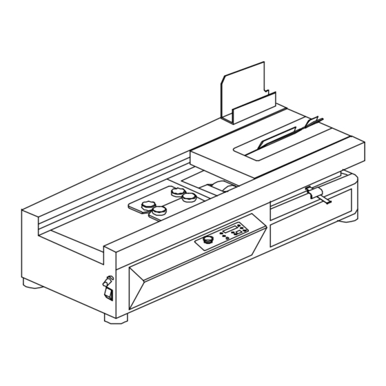
Page 7: Part Names
3. Part names (1) Nipping Station (2) Glue Tank (3) Notching Station (4) Clamp Station (5) Control Panel (6) Nipping Pressure Control 4. Names and functions of the control panel Name Function LED Display / Example EMERGENCY Stop all the actions of the machine. “STOP”... -
Page 8: Specification
NOTCH / LED Select the notching function during the bookbinding operation. 5. Specification Model DB-250 Perfect Binder Maximum Book Size 12.6” x 15.75” ( 320mm x 400mm ) Minimum Book Size 3.15” x 1.97” ( 80mm x 50mm ) Maximum Binding Thickness 1.6”... -
Page 9: Using The Db-250
6. Using the DB-250 6-1 STARTUP : Turn ON the power switch of DB-250 as shown. ( where “I” for ON; “O” for OFF ) The heater of DB-250 will automatically heat the glue to the preset working temperature and display the status of the heating processes. -
Page 10: Glue Adjustment
6-2 GLUE ADJUSTMENT : The glue level may require adjustment when the thickness of the book or pad varies. Use the following book spine illustrations for guidelines. • Increasing the holt-melt glue when Hollow middle Round • Decreasing hot-melt glue when Too much glue on both sides Nail head •... -
Page 11: Nipping Pressure Control
This will prevent glue from spilling out of the tank. Glue Replacement 1. Warm up the DB-250 as described in the STARTUP section on page 5. 2. Make sure the draining tray is warped by Aluminum foil and positioned underneath the glue tank so that the tank drains into it. -
Page 12: Manual Mode
6-5 MANUAL MODE : After the “STARTUP” procedures, the DB-250 will automatically set itself MANUAL operation and flashing "LOAD BOOK" display. Note that the “NOTCH” LED is ON. (1) Press the “OPEN” button and place the book block inside the clamps. Be sure to follow... - Page 13 After the first notching process, the clamp station will remain to the left side of DB-250 and the LED display of the control panel will display and flash "LOAD COVER". Center the cover sheet and adjust the side guide: Measure the width of the book plus half the thickness of the spine.
-
Page 14: Auto Mode
Then you will see the flashing "PUSH START" display again. (3) Press the “START” button. The LED DISPLAY of control panel will show the “ß” sign. The clamp station will move to the left side of DB-250 and will remain there. - Page 15 Meanwhile, the LED display of control panel will count once for the total binding amount as shown. The DB-250 will flash "LOAD BOOK" display. Place the same thickness of book block onto the clamp as the label instructions on the clamp.
-
Page 16: Padding Mode
6-7 PADDING MODE: “PAD” is one of the DB-250 operations that apply to special binding applications such as binding without cover sheet. Press “FUNCTION” button to switch to “PAD” operation. The “PAD” LED will be lit and display flashing "LOAD PAD" as shown. -
Page 17: Standby Mode
Note that you have to wait a few minutes when LED displays "WARM00" status. The glue tank of DB-250 will be reheated, then the control panel will display and flash "LOAD BOOK" after "HOT" status. -
Page 18: Mechanism, Function And Adjustment
MACHINERY Mechanism, Function and Adjustment Notching Station 1-1 Mechanism The mechanism of notching station is shown below. 1-2 Function The purpose of notching is to enhance the solidification of the bookbinding. The notching blade makes numerous cuts on the spine of the book so that the melted glue can penetrate the binding area. -
Page 19: Adjustment
1-3 Adjustment In order to get appropriate depth of the cuts and the precision of the center path for clamp station, the notching station can be adjusted to the up, down, right, and left positions as shown. Note that notching surface should be adjusted evenly on both sides to prevent tilting the notching surface. -
Page 20: Glue Tank
2. Glue Tank 2-1 Mechanism The mechanism of glue tank is shown below. 2-2 Function Providing a layer of melted glue on the spine of the book so that cover and inner pages can be bound together. The glue scraper of glue tank controls the quantity of the melted glue on the glue drum while the glue meter controls the thickness of melted glue that is applied to the spine. - Page 21 3) To adjust the standard gap for the glue meter, you can use the screws on the glue tank bracket to adjust the position of the glue tank. Then measure the distance between the ruler and the highest point of glue drum. To adjust the height of the glue meter, loosen the two sets of screws located on each end.
-
Page 22: Nipping Station
3. Nipping Station 3-1 Mechanism The mechanism of nipping station is shown below. 3-2 Function Provided a flat surface for the book block, when there are being placed into the clamp station. It also provides the nipping force to form the cover around the spine of the book. - Page 23 • Position change on the position disc of nipping station: There are three positions of the nipping station for executing the clamping, the cover, and the nipping processes. The LED of the sensor ( LS3 or LS4 ) goes on when the notch of position disc travels through the trench of the sensor as shown below: ( Clamping Position ) Bearing...
- Page 24 If the spine is not being nipped evenly, adjust the nipping plates as follows: • Adjusting on the Nipping Plates: Push each side of nipping plates to find out which side is too tight. Then use the nipping plate screws to do the fine adjustment until both sides have the same tension.
-
Page 25: Clamp Station
4. Clamp Station 4-1 Mechanism The mechanism of clamp station is shown below. 4-2 Function Holding the book block for the notching, gluing, and nipping processes of bookbinding. 4-3 Adjustment The acceptable spine of a book and the shape of book block after being clamped are shown below. - Page 26 • Adjusting for round or hollow middle : If you see the spine of the book has a round or hollow middle, most of the cases you may 1) increase the certain quantity of hot-melt glue by the glue meter or 2) turn VR knob clockwise to increase the nipping force to correct it.
-
Page 27: Driving Section
5. Driving Section 5-1 Mechanism The mechanism for driving section is shown below. 5-2 Function Provides driving power to move and locate the clamp station over the glue drum and notching station, then return it back to the nipping station for covering and binding. 5-3 Adjustment Adjust tensioner to eliminate any slack in chain. -
Page 28: Construction Block Layout
Electricity 1. Construction block layout 1. SWITCHING POWER 2. CONTROL PANEL (TG200B1) POWER 3. CLAMP STATION 11. EMERGENCY RIGHT SENSOR (LS1) SWITCH (TG200A1) (TG200C2) 4. CLAMP STATION 12. THERMOSTAT LEFT SENSOR (LS2) 5. NIPPING STATION 13. FUSE BOARD SENSOR (LS3/LS4) (TG200D2) 6. - Page 29 2. Outline of each block 1. Switching Power Converts AC110V / 220V into DC 5V and DC 12 V. 2. Control Panel ( TG200B1 ) Displays the current status of the machine. 3. Clamp Station Right Sensor ( LS1 ) Detects and locates the clamp station at its home position.
- Page 30 12. THERMOSTAT Sets the working temperature of the glue. 13. Fuse Board ( TG200D2 ) Protects the motors and heater from overloading. 14. Main Motor ( M1 ) Drives the clamp station to the left and right positions. It also drives the glue drum when the clamp station is moving to the right position of the machine.
-
Page 31: Checking The Motions – Test Modes
You should see the “TEST2” in the LED display. After performing the “WARM”, “HOT”, and “S-TEST” processes, the DB-250 will display “MOTOR 1” in the LED display. Then you can select the following module tests by pressing “OPEN” or “CLOSE”... -
Page 32: Circuit Diagrams
4. Circuit Diagrams Main Schematic Diagrams • CPU ( TG200A1 ) -
Page 33: Control Panel ( Tg200B1 )
• CONTROL PANEL ( TG200B1 ) - Page 34 • SSR ( TG200C2 )
-
Page 35: Fuse Board ( Tg200D2 )
• FUSE BOARD ( TG200D2 ) -
Page 36: Wiring Diagram
Wiring diagram LEGEND Motor Capacitor 1 Motor Capacitor 2 Motor Capacitor 4 Motor Capacitor 6 CCW: Counter Clockwise Clockwise EMG: Emergency Switch LS1: Limit Sensor 1 LS2: Limit Sensor 2 LS3: Limit Sensor 3 LS4: Limit Sensor 4 Main Motor Nipping Motor Notching Motor Clamp Motor... -
Page 37: Pin Assignments
Pin Assignments Power LED Display S-Power Capacitors Heater Emergency Motors Relay Fuse... -
Page 38: Frame / Exterior Section
Parts Catalog Frame / Exterior Section INDEX PARTS NO. DESCRIPTION AREA E4005 Compartment Pillar E6001 Main Frame E6019 Front Guide E6020 Rear Guide E6004 PCB Box Bracket E6005 Control Panel Bracket E6021 Front Cover E6007 Rear Cover E6025 Control Panel Cover E6023 Front Guide Cover... - Page 39 INDEX PARTS NO. DESCRIPTION AREA E6022 Rear Guide Cover E6013 Glue Tank Bottom Cover E6017 Cover Sheet Holder E6018 Control Panel Hanger E6201 Glue Tank Top Cover E6401 Notching Station Cover E6403 Glue Tank Bracket E6405 Shipping Bracket 1 E6406 Shipping Bracket 2 E6408 Shipping Bracket 3...
-
Page 40: Notching Station Section
Notching Station Section INDEX PARTS NO. DESCRIPTION AREA E3008 Notching Roller Shaft E3003 Notching Wheel E3004 Notching Roller E3005 Notching Position Spacer E3006 Notching Position Arm G3001 E3007 Notching Station Body E6304A Notching Cover E6304B Notching Cover E6303 Notching Position Connector G3001 E6402 Notching Station Bracket... -
Page 41: Glue Tank Section
Glue Tank Section INDEX PARTS NO. DESCRIPTION AREA E2001 Glue Tank Body E2002 Glue Meter Shaft E2003 Glue Wheel Shaft E2004 Glue Scraper Shaft E2005 Glue Wheel Bearing E2006 Glue Tank Shaft Unit E6202 Glue Scraper Plate E6203 Glue Heater Cover E7305 Glue Tank Heater E7306... -
Page 42: Nipping Station Section
Nipping Station Section... - Page 43 INDEX PARTS NO. DESCRIPTION AREA E1001 Nipping Station Base E1002 Nipping Station Body Part G1001 E1003 Nipping Station Swing Shaft E1004 Lifting Cam for Nipping Station E1006 Nipping Plate E1007 Lifting Bracket E1008 Bearing Shaft for Lifting Bracket E1024 Nipping Slide Block G1002 E1010 Nipping Station Timing Shaft...
-
Page 44: Clamp Station Section
5. Clamp Station Section... - Page 45 INDEX PARTS NO. DESCRIPTION AREA E5003 Clamp Wheel Seat G5001 E5004 Clamp Driving Connector E5008 Clamp Worm Support E5009 Clamp Left-Right Worm G5002 E5010 Clamp Worm Seat G5003 E5012 Clamp Wheel Support E6502 Clamp Station Cover E6512 Clamp Station Body E6513A Clamp Adjustment E6513B...
-
Page 46: Driving Section
6. Driving Section INDEX PARTS NO. DESCRIPTION AREA E4001 Driving Shaft Screw E4002 Driving Shaft Slide Seat G4001 E4003 Driving Shaft E4004 Sprocket Shaft 1 E4006 Chain Adjustment E7101 Main Motor ( M1 ) G4002 E7101-G Main Motor Reduced Gear Box E7402-W Main Motor Power Connector - female G4002... -
Page 47: Electricity Section
7. Electricity Section INDEX PARTS NO. DESCRIPTION AREA E6011 PCB Box Base E6012 Temperature Switch Bracket E6014 Capacitance Base E6015 PCB SSR Cover E6016 PCB CPU Cover E6404 Photo Switch Bracket E7201 TG-200 CPU E7203 TG-200 SSR E7202 TG-200 Panel E7204 TG-200D2 Fuse PCB E7205... -
Page 48: Assemble Parts List
INDEX PARTS NO. DESCRIPTION AREA E7309 Control Panel Cable ( 16 pin ) E7401-M Nip / Notch Motor Power Connector - male E7401-W Clamp Motor Power Connector - female G6001 E7402-M Main Motor Power Connector - male E8301 Control Panel Tag E8405 Wiring Hose with Wires G6001... -
Page 49: Daily Cleaning Procedures
4. Press the "START" and "CLEAR" keys again, the clamp station will return to its home position. Open the clamps to the maximum position. Clean their surfaces and wax them. 5. Turn the DB-250 off. 2. General Maintenance Procedures Depends on how frequency you use the machine, we recommend that you should do the following maintenance at least once during three-month period. -
Page 50: Maintenance Parts List
(3) Checking the Motions – TEST2 Please refer to the “Checking the motions” section of the electricity on page 27 for details. (4) Making Sample Books Run the following modes and make some sample books to see if every mode is functioning properly and doesn’t form the nail head or round angle on the spine of books. - Page 51 PARTS DESCRIPTION SECTION E7101-G Main Motor Reduced Gear Box (6) Driving E7102 Nipping Station Motor ( M2 ) (4) Nipping Station E7102G Nipping Motor Reduced Gear Box (4) Nipping Station E7103 Notching Motor ( M4 ) (2) Notching Station E7104 Clamp Motor ( M6 ) (5) Clamp Station E7104-G...
- Page 52 PARTS DESCRIPTION SECTION E8302 Glue Tank Tag (1) Frame / Exterior Section E8303 Notching Station Tag (2) Notching Station E8304 Clamp Station Ruler for Binding Width (5) Clamp Station E8305 Glue Level Indicator (3) Glue Tank E8401 Machine Leg (1) Frame / Exterior Section E8402 Cover Ruler (4) Nipping Station...
-
Page 53: A - Troubleshooting Guide For Spine Adjustment
APPENDIX A - Troubleshooting Guide for Spine Adjustment Note: Before you perform the spine adjustment, try to use the following methods to correct it. (A) Round / hollow middle through the spine (1) Increase the certain quantity of hot-melt glue by the glue meter. (2) Turn VR knob clockwise to increase the nipping pressure. -
Page 54: A1 Clamp Spine Adjustment
A1 - Clamp Spine Adjustment (A) Round / hollow middle through the spine LL = RL, RR = LR (1) Increasing certain quantity of the hot-melt glue by glue meter, then make some books to see if the spine has been improved on both sides. (2) Slightly turn the VR knob clockwise to increase the nipping pressure, then make some books to see if the spine has been improved on both sides. -
Page 55: B) Nail Head Through The Spine
(B) Nail head through the spine LL = RL, RR = LR (1) Decreasing certain quantity of the hot-melt glue by glue meter, then make some books to see if the spine has been improved on both sides. (2) Slightly turn the VR knob counter clockwise to decrease the nipping pressure, then make some books to see if the spine has been improved on both sides. -
Page 56: C) Left-End Round / Hollow Middle
(C) Left-end round / hollow middle LL = RL, RR = LR You have to do the adjustment for the clamps. Slightly loosen the left-side bottom lock nuts, then gradually tighten the left bottom screws of the clamps until there is no gap between the spine and the nipping plate surface when you close the clamps. -
Page 57: E) Left-End Nail Head
You have to do the adjustment for the clamps. Slightly loosen the right-side bottom lock nuts, then gradually tighten the right bottom screws of the clamps until there is no gap between the spine and the nipping plate surface when you close the clamps. -
Page 58: F) Right-End Nail Head
(F) Right-end nail head LL = RL, RR = LR You have to do the adjustment for the clamps. Slightly loosen the right-side upper lock nuts, then gradually tighten the right upper screws of the clamps until there is no gap between the spine and the nipping plate surface when you close the clamps. -
Page 59: G) Left-End Nail Head And Right-End Round
(G) Left-end nail head and right-end round LL = RL, RR = LR You have to reset the clamps. Loosen all the lock nuts, then gradually tighten all the screws of the clamps until there is no gap between the spine and the nipping plate surface when you close the clamps. -
Page 60: A2 Nipping Plates Spine Adjustment
A2 - Nipping Plates Spine Adjustment One side round and one side square LL ≠ RL RR ≠ LR You have to adjust the nipping plates. Push each side of nipping plate to find which side is loosing or too tight. Then slightly loosen all the nipping plate adjustment screws on each plate. -
Page 61: B1 Error Messages
B - Troubleshooting and Error Message B1 - Error Message LED Display Description Cause of Error ERR = L1 Clamp station is 1. MT1 - fuse blown. not in the home position. 2. LS1 - sensor is bad. 3. MT1 - motor problem. ERR = L2 Clamp station is 1. -
Page 62: B2 Troubleshooting And Correction
B2 - Troubleshooting and Correction Check if clamp station Check if LS1 LS1 has been ERR=L1 has returned to the is functioning damaged. right position ? OK ? Change LS1 Check the LS1 connector and the related circuits Check if the M1 fuse M1 fuse has is functioning OK ? been damaged. - Page 63 Check if nipping Check if LS3 LS3 has been ERR=L3 station has returned to is functioning damaged. the lowest position ? OK ? Change LS3 Check the LS3 connector and the related circuits Check if the M2 fuse M2 fuse has is functioning OK ? been damaged.
- Page 64 Check if the hot-melt Thermostat has ERR=T1 glue has been melted been damaged. completely ? Change thermostat. Check if the heater Heater fuse has been fuse is functioning OK ? damaged. Change heater fuse. Heater has been damaged. Change heater. Check if the heater Heater fuse has TEMP...
-
Page 65: C - Setup For Timers
C - Setup for Timers To enter the timer setup menu, you will need to press and hold down both the “OPEN” and “CLOSE” buttons, then turn the power on. You should see “SET TR” in the LED display. Press the “FUNCTION” button to sequentially display TR1, TR2, TR3, TR4, TR5, TR6, “SAVE”, “CANCEL”, and “RESET”.
Need help?
Do you have a question about the DB-250 and is the answer not in the manual?
Questions and answers