
Related Manuals for Duplo DB-280


Summary of Contents for Duplo DB-280
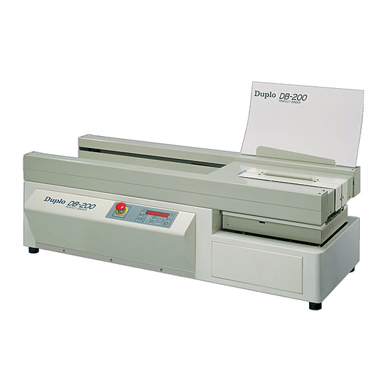
- Page 1 Instruction Manual PERFECT BINDER MODEL: DB-280, DB-200, DB-660, DB-700 Duplo Taiwan Corporation TEL:886-2-27212117 FAX:886-2-27211669 8F., NO.2, SEC.4, CHUNG HSIAO E.RD., TAIPEI,TAIWAN ~ 1 ~ ...
-
Page 2: Table Of Contents
Table of Contents Page Cover/Table Of Contents SAFETY INSTRUCTION SAFETY REGULATION WARNING PLATE LOCATION OF SAFETY SIGNS ON THE PRESS BRAKE IS SHOWN IN THE FIGURE BELOW NAME PLATE SPECIFICATION SPECIFICATION MACHINE NOISE FUNCTION OF THE MACHINE LEGEND OF THE MACHINE MACHINE DIMENSION INSTALLATION SAFETY RULES FOR MACHINE MOVEMENT... - Page 3 ~ 3 ~ ...
- Page 4 ~ 4 ~ ...
- Page 5 ~ 5 ~ ...
- Page 6 ~ 6 ~ ...
- Page 7 ~ 7 ~ ...
-
Page 8: Safety Instruction
DB-280 has implemented the secondary thermostat to protect the glue tank temperature over 410F (210。C). When it occurs, the power of DB-280 will be automatically turned off. You have to wait for the glue tank to cool down before you can restart the machine. If this problem occurs again, call your authorized dealer for service. -
Page 9: Safety Regulation
1.1 Safety Regulation • KNOW YOUR MACHINE. For your own safety, read the owner's manual carefully. Learn its application and limitations as well as specific potential hazards pertinent to this machine. • KEEP GUARDS IN PLACE AND IN WORKING ORDER. ... - Page 10 • Protective guards and shields must be in place at all times unless that specific part requires servicing. • Never clean or remove chips while the machine is running. • Do not remove or alter warning labels and replace any that become obscured. ...
-
Page 11: Warning Plate
1.2 Warning Plate This machine has warning symbols attached on it as shown below to ensure proper and safe operation. These symbols are used on the machine to indicate points or instances of specific danger to operating personnel. Make sure to memorize these symbols and bring them to the attention of others as and when necessary. -
Page 12: Location Of Safety Signs On The Press Brake Is Shown In The
1.3 Location of safety signs on the press brake is shown in the figure below ~ 12 ~ ... -
Page 13: Name Plate
1.4 Name Plate ~ 13 ~ ... -
Page 14: Specification
2 Specification 2.1 Specification Model DB-280 12.6” x 15.75” ( 320mm x 400mm ) Maximum Book Size Minimum Book Size 3.15” x 1.97” ( 80mm x 50mm ) Maximum Binding Thickness 1.6” ( 40mm ) Glue Warm Up... - Page 15 Model DB-660 11.7” x 15.53” ( 297mm x 420mm ) Maximum Book Size Minimum Book Size 5.7” x 5.51” ( 145mm x 140mm ) Maximum Binding Thickness 2.3” ( 60mm ) Glue Warm Up 40~50 minutes ( varies depending upon glue type ) Glue Warm Up in Stand-by Mode 5 minutes Cycle Speed...
-
Page 16: Machine Noise
2.2 Machine Noise DECLARED NOISE EMISSION VALUES in accordance with ISO 7960. Operating Declared A-weighted Sound Power Level, 81.8 Lward, in dB re 1 pW Declared A-Weighted Emission Sound Pressure Level , lpAd , in dB re 20 μPa , at 68.8 ... -
Page 17: Function Of The Machine
2.3 Function of the Machine 1. Provided a flat surface for the book block, when there are being placed into the clamp station. It also provides the nipping force to form the cover around the spine of the book. ... -
Page 18: Legend Of The Machine
2.4 Legend of the Machine Drawing ~ 18 ~ ... -
Page 19: Machine Dimension
2.5 Machine Dimension Drawing DB-280 ~ 19 ~ ... - Page 20 DB-200 ~ 20 ~ ...
- Page 21 DB-660 ~ 21 ~ ...
- Page 22 DB-700 ~ 22 ~ ...
-
Page 23: Installation
specifications table about haulage: Variant NO. Basic Variant Identification Unit DB-280 Environment temperature °C +0°C~+40°C Environment humidity Machine size (L.W.H) 1250x560x470 Machine weight Center-of-gravity position (L.W.H) -
Page 24: Lifting The Machine/Drawing
3.2 Lifting the Machine / Drawing At least four people to lift up the machine ~ 24 ~ ... -
Page 25: Selection Of Location
2. Keep the machine away from the direct sunlight and heat sources such as stoves, heaters and radiators. 3.4 Installation/Drawing Note: You must remove the three red shipping brackets before installing your DB-280 The procedures for installation: Remove the red shipping bracket located on the left side of the clamp station as shown. -
Page 26: Installation And Leveling
It is important to connect this machine to the correct voltage in the factory power source. Use only an independent power source. Table for power supplies requirement: Model Voltage Current Breaker capacity Wire size DB-280 9.7Kw 220V 2.08mm² DB-200 9.7Kw 220V 2.08mm²... -
Page 27: Check Connection Of Power Wires
3.8 Check Connection of Power Wires After the power wires have been connected it is necessary to check if the power wires are connected to the correct connection points. Check periodically to ensure the following : The plug is not excessively hot The power cord is not damaged The plug is firmly plugged into the outlet ~ 27 ~ ... -
Page 28: Operation
4 Operation 4.1 Operator Position (Drawing) ~ 28 ~ ... -
Page 29: Control Panel
4.2 Control Panel ~ 29 ~ ... -
Page 30: Emergency Stop
Name Description LED Display / Example EMERGENCY Stop all the actions of the machine. Except “STOP” (flashing) when “HOT” shows on the LED DISPLAY. STAND BY / Temporarily lowers the temperature of glue STBY00 tank so it won’t burn the glue when the machine is not operated. -
Page 31: Operation Procedure
When the glue temperature has reached the working temperature, DB-280 performs the self-test and stirs the melting glue. DB-280 is ready for bookbinding and set to MANUAL mode for your desired operation. At this moment, the control panel will display and flash "LOAD BOOK"... - Page 32 4.4.1 Glue Adjustment The glue level may require adjustment when the thickness of the book or pad varies. Use the following book spine illustrations for guidelines. • Increasing the holt-melt glue when Hollow middle Round • Decreasing hot-melt glue when Too much glue on both sides OR Nail head Adjusting the glue level :...
- Page 33 4. Turn the knob clockwise to lock the setting Note that the thickness of the cover sheet is an important factor for you to make a good spine. Use only the suitable thickness of the cover sheet associated with the appropriate glue-meter position to make a good book.
- Page 34 Glue Replacement 1. Warm up the DB-280 as described in the STARTUP section on page 5. 2. Make sure the draining tray is warped by Aluminum foil and positioned underneath the glue tank so that the tank drains into it.
- Page 35 4.4.3 Manual Mode After the “STARTUP” procedures, the DB-280 will automatically set itself MANUAL operation and flashing "LOAD BOOK" display. Note that the “NOTCH” LED is ON. (1) Press the “OPEN” button and place the book block inside 1 the clamps. Be sure to follow the label instructions on the...
- Page 36 After the first notching process, the clamp station will remain to the left side of DB-280 and the LED display of the control panel will display and flash "LOAD COVER". Center the cover sheet and adjust the side guide: Measure the width of the book plus half the thickness of the spine.
- Page 37 Then you will see the flashing "PUSH START" display again. (3) Press the “START” button. The LED DISPLAY of control panel will show the “ ” sign. The clamp station will move to the left side of DB-280 and will remain there. ~ 37 ~ ...
- Page 38 "UNLOAD" so that you can remove the finished book from the right end. Meanwhile, the LED display of control panel will count once for the total binding amount as shown. The DB-280 will flash "LOAD BOOK" display. ...
- Page 39 4.4.5 PADDING MODE: “PAD” is one of the DB-280 operations that apply to special binding applications such as binding without cover sheet. Press “FUNCTION” button to switch to “PAD” operation. The “PAD” LED will be lit and display flashing "LOAD PAD" as shown.
- Page 40 (2) Having moved to the left position of DB-280, the clamp station will automatically move back to the right position and display "WAIT..". (4) Wait for a few seconds until the LED display of control panel displays “PUSH OPEN” as shown.
- Page 41 “READY” LED will be lit and waiting for your desired operation. Note that you have to wait a few minutes when LED displays "WARM00" status. The glue tank of DB-280 will be reheated, then the control panel will display and flash "LOAD BOOK" after "HOT" status.
- Page 42 4.4.7 TAPE MODE BEFORE USING TAPE MODE INSTALL FOUR OPTIONAL BLOCK PARTS. Press “TAPE” button,LED Display “TAPE” “MODE"instead of ”LOAD”“BOOK” After clamp station goes to left,LED display shows ”LOAD” “TAPE” Press “START” after putting tape, book go back right side then finish the tape mode ATTENTION:...
- Page 43 4.4.8 CASING UNIT CONTROL The casing unit is used for adjusting the distance between book sheets and hard cover, adjusting range 0~10mm Tuning angle 0~180degrees Release the M4 screw first, after adjusting tight the M4 screw. 4.4.9 VACUUM DUST REMOVAL SYSTEM When blade cutting,it brings paper dust, so use vacuum dust removal system to clean.
-
Page 44: Adjustment Of The Machine/Parts
4.5 Adjustment of the Machine/Components 4.5.1 Notching Station Function The purpose of notching is to enhance the solidification of the bookbinding. The notching blade makes numerous cuts on the spine of the book so that the melted glue can penetrate the binding area. ... - Page 45 Changing the blade 1. Open one side of the notching station 2. Loosen the blade screw and remove the old blade 3. Install the new blade as shown, then set the height of the blade about 3mm above the surface of notching wheel 4.
- Page 46 4.5.2 Glue Tank Function Providing a layer of melted glue on the spine of the book so that cover and pages can be bound together . The glue scraper of glue tank controls the quantity of the melted glue on the glue drum while the glue meter controls the thickness of melted glue that is applied to the spine Adjustment •...
- Page 47 • Setting the glue -adjusting knob to the appropriate positions: Normally, the indicator is set at 1/3 to 1/2 of the arrow mark. • Controlling the quality of a book by means of the glue meter: Note that the thickness of the cover sheet is an important factor for you to make a good spine.
- Page 48 4.5.3 Nipping Station Function Provided a flat surface for the book block, when there are being placed into the clamp station. It also provides the nipping force to form the cover around the spine of the book Adjustment 1.) During the nipping process, the nipping plates must exert an even pressure on the cover in order to form a spine 2.) The nipping swing arms provide this pressure Open the nipping station, then turn the swing arms counter-clockwise to the position shown.
- Page 49 • Position change on the position disc of nipping station There are three positions of the nipping station for executing the clamping, the cover, and the nipping processes. The LED of the sensor (LS3 or LS4) goes on when the notch of position disc travels through the trench of the sensor as shown below: 1.) Clamping: when the bearing is at the highest point 2.) Cover: when the bearing is at the lowest point...
- Page 50 3.) Nipping: when the bearing is at the sub-high point If the spine is not being nipped evenly, adjust the nipping plates as follows: • Adjusting on the Nipping Plates 1.) Push each side of nipping plates to find out which side is too tight. 2.) Then use the nipping plate screws to do the fine adjustment until both sides have the same tension.
- Page 51 • Position Adjustments on Nipping Station (A) The level of nipping station should be adjusted evenly on the corresponding ends to prevent tilting the nipping station surface, by level adjusting screws. (B) The centerline of the nipping station must match the projected centerline of the clamp station by the front/rear adjusting screws.
- Page 52 4.5.4 Clamp Station Function Holding the book block for the notching, gluing, and nipping processes of bookbinding. Adjustment The acceptable spine of a book and the shape of book block after being clamped are shown below. If you find different shapes such as “round”, “hollow” and “nail head” for one end or both ends, remove the clamp covers, then adjust the screws on both clamps.
- Page 53 LL and LR corners are nail head: it means that the left spine of the book should be lift up to make the left side of the spine rounder. So you can increase adjustment on both NON-OP Plate1 and OP Plate 1,and making book to see LL and LR corners are ok or not.
- Page 54 LL and LR corners are round: it means that the left spine of the book should be push down to make the left side of the spine to be more right angle. So you can increase adjustment on both NON-OP Plate 2 and OP Plate 2,...
-
Page 55: Maintenance
4. Press the "START" and "CLEAR" keys, the clamp station will return to its home position. Open the clamps to the maximum position. Clean their surfaces and wax them. 5. Turn the DB-280 off. Three-month period Depends on how frequency you use the machine, we recommend that you should do the following maintenance at least once during three-month period. -
Page 56: Lubrication
1. Open the clamps to the maximum position then turn off the power of the machine. 2. Take apart the clamps from the clamp station. 3. Clean the residual glue that might be on the clamps. 4. Install the clamps to the clamp station. 5. - Page 57 ~ 57 ~ ...
- Page 58 ~ 58 ~ ...
- Page 59 ~ 59 ~ ...
-
Page 60: Test Of Safety Devices
“TEST2” in the LED display. After performing the “WARM”, “HOT”, and “S-TEST” processes, the DB-280 will display “MOTOR 1” in the LED display. Then you can select the following module tests by pressing “OPEN” or “CLOSE” button to toggle “MOTOR 1”, “MOTOR 2”, “MOTOR 4”, and “MOTOR 6”... -
Page 61: Electric
6 Electric 6.1 Safety Rules For Electrical Control System 1.) Only personnel who are properly trained and have adequate knowledge and skill should undertake all electrical/electronic troubleshooting and repair. 2.) Do not alter or bypass protective interlocks. 3.) Before starting, read and observe all warning labels. 4.) When trouble shooting make sure the power source has been disconnected and main switch has been locked. -
Page 62: Electrical Drawing
6.2 Electrical Drawing ~ 62 ~ ... - Page 63 ~ 63 ~ ...
- Page 64 ~ 64 ~ ...
- Page 65 ~ 65 ~ ...
- Page 66 ~ 66 ~ ...
- Page 67 ~ 67 ~ ...
- Page 68 ~ 68 ~ ...
-
Page 69: Electrical Part List
6.3 Electrical Component List Function Symbol Specification Motor 4RK25GN Motor 5TK50GN Motor 5IK40A Motor 2GN30K Power supply EMG STOP 1A1B Circuit breaker heater Temp switch E.G..O Temp switch 100℃ Temp switch 210℃ Limit switc Z-15GW-B Photo sensor ~ 69 ~ ...
Need help?
Do you have a question about the DB-280 and is the answer not in the manual?
Questions and answers