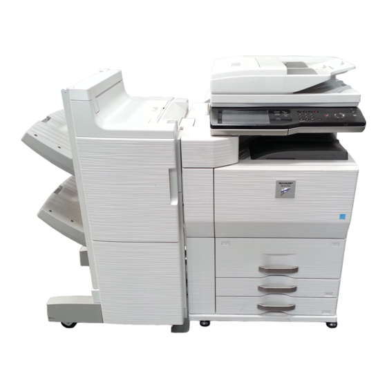
Sharp MX-M623N Installation Manual
Digital multifunctional system
Hide thumbs
Also See for MX-M623N:
- Start manual (56 pages) ,
- Operation manual (879 pages) ,
- Brochure & specs (13 pages)
Table of Contents
Advertisement
Quick Links
[1]
MX-M623N/M623U/
M753N/M753U . . . . . . . . . . . . . . . . . 1-1
[2]
MX-LC10 . . . . . . . . . . . . . . . . . . . . . 2-1
[3]
MX-LCX3N . . . . . . . . . . . . . . . . . . . . 3-1
[4]
MX-CF10 . . . . . . . . . . . . . . . . . . . . . 4-1
[5]
MX-FN15/FN16 . . . . . . . . . . . . . . . . 5-1
[6]
AR-PN4 . . . . . . . . . . . . . . . . . . . . . . 6-1
[7]
MX-FN14 . . . . . . . . . . . . . . . . . . . . . 7-1
[8]
MX-PN10 . . . . . . . . . . . . . . . . . . . . . 8-1
[9]
MX-FXX2 . . . . . . . . . . . . . . . . . . . . . 9-1
[10] MX-FWX1. . . . . . . . . . . . . . . . . . . . 10-1
[11] MX-KBX2 . . . . . . . . . . . . . . . . . . . . 11-1
[12] AR-SU1 . . . . . . . . . . . . . . . . . . . . . 12-1
[13] MX-EBX3 . . . . . . . . . . . . . . . . . . . . 13-1
Parts marked with "
" are important for maintaining the safety of the set. Be sure to replace these parts with
specified ones for maintaining the safety and performance of the set.
INSTALLATION MANUAL
DIGITAL MULTIFUNCTIONAL SYSTEM
MODEL
CONTENTS
[14] MX-FR22U . . . . . . . . . . . . . . . . . . . 14-1
[15] MX-PB13 . . . . . . . . . . . . . . . . . . . . 15-1
[16] MX-PKX1 . . . . . . . . . . . . . . . . . . . . 16-1
[17] MX-PUX1 . . . . . . . . . . . . . . . . . . . . 17-1
[18] MX-SMX3. . . . . . . . . . . . . . . . . . . . 18-1
[19] AR-PF1 . . . . . . . . . . . . . . . . . . . . . 19-1
[20] MX-NSX1 . . . . . . . . . . . . . . . . . . . . 20-1
[21] MX-AMX1. . . . . . . . . . . . . . . . . . . . 21-1
[22] MX-AMX2. . . . . . . . . . . . . . . . . . . . 22-1
[23] MX-AMX3. . . . . . . . . . . . . . . . . . . . 23-1
[24] DRY HEATER INSTALLATION . . . 24-1
SHARP CORPORATION
CODE: 00ZMXM753/I1E
MX-M623N
MX-M623U
MX-M753N
MX-M753U
This document has been published to be used
for after sales service only.
The contents are subject to change without notice.
Advertisement
Table of Contents

Related Manuals for Sharp MX-M623N


Summary of Contents for Sharp MX-M623N
-
Page 1: Table Of Contents
INSTALLATION MANUAL CODE: 00ZMXM753/I1E DIGITAL MULTIFUNCTIONAL SYSTEM MX-M623N MX-M623U MX-M753N MX-M753U MODEL CONTENTS CONFIGURATION [14] MX-FR22U ....14-1 MX-M623N/M623U/ [15] MX-PB13 ....15-1 M753N/M753U . - Page 2 3. Combination of options ......ii [19] AR-PF1 [1] MX-M623N/M623U/M753N/M753U 1. Unpacking ....... 19- 1 1.
-
Page 3: Configuration
CONFIGURATION MX-M753N Service Manual 1. Main unit and option MX-FN15 FINISHER AR-PN4A/B/C/D PUNCH MODULE MX-M623N/M753N SF-SC11 MX-M623U/M753U STAPLE CARTRIDGE DIGITAL MULTIFUNCTIONAL MX-LC10 MX-FN16 SYSTEM LARGE CAPACITY TRAY SADDLE STITCH FINISHER AR-SC3 STAPLE CARTRIDGE MX-FN14 FINISHER MX-LCX3N LARGE CAPACITY TRAY MX-PN10A/B/C/D... - Page 4 3. Combination of options MX-M623N MX-M623U Product Section Name Model name Remarks MX-M753N MX-M753U key target Paper feed system LARGE CAPACITY TRAY MX-LC10 LARGE CAPACITY TRAY MX-LCX3N Paper exit system INSERTER MX-CF10 FINISHER MX-FN15 SADDLE STITCH FINISHER MX-FN16 FINISHER MX-FN14...
-
Page 5: M753N/M753U
Use of a step-up transformer is also available. In this case, the Temperature: 10 to 35°C capacity must be great enough for the max. power consumption of the machine. Humidity: 20 to 85% RH Atmospheric pressure: 590 to 1013hPa (altitude: 0 to 2000 m) MX-M753N MX-M623N/M623U/M753N/M753U 1 – 1... - Page 6 • When repairing or replacing an electronic part, perform the procedure on an anti-static mat. (5) Vibration Avoid installation near a machine which produces vibrations. If vibrations are applied to the copier machine, copy images may be deflected and a trouble may be caused. MX-M753N MX-M623N/M623U/M753N/M753U 1 – 2...
-
Page 7: Unpacking
Since the hard disk drive is built in the machine, use care not to exert vibrations or shocks to the machine when in transit. B. Delivery Remove the packing materials prior to installation in the office envi- ronment. Lift the machine slightly, and remove the bottom pad R. MX-M753N MX-M623N/M623U/M753N/M753U 1 – 3... - Page 8 NOTE: When the machine is moved over a bump, hold the grip on the right side of the machine to lift and cross the bump over. This is because the casters may be broken for a big bump. MX-M753N MX-M623N/M623U/M753N/M753U 1 – 4...
-
Page 9: Installation
(2) Tray rotation release plate lock release Remove the paper feed tray rotation plate fixing screw and the label of note for tray. [Tray 1, Tray 2] Insert the bottom tray into the main unit. [Tray 3, Tray 4] MX-M753N MX-M623N/M623U/M753N/M753U 1 – 5... - Page 10 Hold the strap of the developing unit and remove the develop- ing unit. Remove the separation pawl fixing block from the process unit. Remove the screws and remove the DV cover. Replace the left door. MX-M753N MX-M623N/M623U/M753N/M753U 1 – 6...
- Page 11 To use special paper, use tray 3. (2) Tab paper setting To use tab paper, install the exclusive-use guide tray 3. Note that tray 4 cannot be used. Remove the exclusive-use guide from the storage position left inside of the machine. MX-M753N MX-M623N/M623U/M753N/M753U 1 – 7...
- Page 12 Address Control Settings Receive/Forward Document Filing Printer Condition USB-Device Check Settings Control Touch the [Tray Settings] key. System Settings Back Paper Tray Settings Tray Settings Paper Type Registration Auto Tray Switching Custom Size Registration (Bypass) MX-M753N MX-M623N/M623U/M753N/M753U 1 – 8...
- Page 13 Set the copy density level to “Manual 3” in the Text/Printed Photo to the darker level. The density changing direction must not be mode (Manual). reversed. In addition, all the picture quality adjustment settings in the user adjustment mode must be set to the default (center). MX-M753N MX-M623N/M623U/M753N/M753U 1 – 9...
- Page 14 • If the data are kept, the setup values and the adjustment values can be entered without adjustments, shortening the servicing time. NOTE: After completion of option installation, revise all the firm- ware to the latest version. MX-M753N MX-M623N/M623U/M753N/M753U 1 – 10...
-
Page 15: Mx-Lc10
[2] MX-LC10 Gently pull out the large capacity tray until it stops. MX-M753N Service Manual The large capacity tray until it stops. Unpacking A. Pulling out of the large capacity tray (A4) unit Pull out the large capacity tray (A4) unit and packing parts. Remove the paper feed base fixing screw (1 pc.) of the large capacity tray. - Page 16 C. Check the packed items B. Attach the mounting plate upper and the lower front/rear connecting plate Check that all the items are included in the package. Attach the mounting plate upper (Package part No. 1) with the fixing screw A (Package part No. 4) to the installation part of right side of the main unit.
- Page 17 C. Attach of the large capacity tray to the main Note 2) unit Turn the lock release screw of the front cover counterclockwise to loosen and check that the screw is free. Hold the grips of the front and the rear cabinets with both hands, and lift the left side.
- Page 18 D. Adjusting the casters Connect the large capacity tray interface harness connector to the main unit connector, and tighten the connector screw to fix After installing the large capacity tray to the main unit, loosen the connector. the screws (one in the front and one in the rear) of the adjust- ment caster mounting plate attached to the lower side of the large capacity tray.
- Page 19 a. Side plate size switch Loosen the fixing screw (flat screw 1pc.) of the auxiliary guide. Remove the four fixing screws (blue) which are fixing the Change the mark position ( ) of the auxiliary guide and the upper and the lower sections of the side plate F and the side cassette R from A4 to LT, and fix them with the fixing screw plate R.
- Page 20 G. Turn ON the main power switch of the main Push the paper feed tray slightly, and return the disabled stop- per to the original position, and fix with the fixing screw (1pc.). unit Connect the power plug of the main unit into the power outlet. Open the front cabinet of the main unit.
-
Page 21: Mx-Lcx3N
[3] MX-LCX3N MX-M753N Service Manual A. Turn off the power of the main unit Unpacking Turn OFF the power switch on the operation panel. (Removal of the main unit) Open the front cabinet. Turn OFF the power switch in the front cabinet of the main unit. Installation <Before installation>... - Page 22 B. Fixing material removal Remove the fixing material inside the large capacity tray. Remove the fixing material from the large capacity paper feed tray. Remove three fixing screws (3 pcs.) of the paper feed table of the LCC. Manually pull out the cassette Push the shaft at the rear side of the front cabinet to release the lock.
- Page 23 D. Installation to the machine and height C. Attach the upper mounting plates and the adjustment lower front/rear connecting plates. Use the edge of the connection plates F/R mounted to the Attach the two upper mounting plates with the rubber portion lower side of the machine and the mark on the mounting plate (★) down to the right side of the main unit using screws A (two in the lower left side of the LCC to check the installation height.
- Page 24 F side <1> Loosen the hex washer based screws on the both ends of the caster movable plate in the front and the rear sides. R side <2> Turn the adjustment screw above to adjust the height. After adjustment with the adjustment screw, tighten the screws on the both ends of the caster movable plate which were loosened in the previous procedure.
- Page 25 <3> Check the height of "D.-1)". If the height is not proper, go <4> Check the height of “D.-1)”. If the height is not proper, to <2>. If the height is proper, install the positioning plates separate the LCC (the procedure is described later) and to the front and the rear sides and fix them with the fixing go to “b”.
- Page 26 • When the upper side is not locked Remove the positioning plate installed to the front and the rear sides of the left lower side of the LCC. Raise the adjuster on the lower side of the LCC right side until the hole shown in the figure below comes at the center, and F side check that it is locked.
- Page 27 Shift the LCC to the right to separate. Side plate size changeover <1> Loosen the blue screws on the front and the rear side of the LCC, and slide the handle section to the neutral position. E. Connect the connector of the large capacity <2>...
- Page 28 H. Set the size. <3> Insert the lead edge of the movable shaft into the hole in the lower section of the rear edge plate with the upper Check to insure that the main body is standby state, and press lever, and lock the rear edge plate to the desired paper the [System setting] key on the operation panel.
- Page 29 [When shifted to the front side] [When shifted to the front side] When the print line is shifted from the center of paper in the direc- When shifting the print line from the paper center in the arrow direc- tion A: tion as shown below: Increase the value.
- Page 30 (3) Mechanical adjustment-2 [When shifted to the rear side] When shifting the print line from the paper center in the arrow direc- Since the regulation plates are adjusted when shipping, there is tion as shown below: basically no need to readjust. If, however, diagonal feed is poorly operated, adjust the regulation plate width and the diagonal feed in 2) Loosen the blue off-center adjustment screws (each 2 pcs.), and the following procedures:...
- Page 31 b. Diagonal feed adjustment Set a sheet of paper on the paper feed base tray and adjust the regulation plate width. (Refer to "a. Regulation plate width Press the lock button on the front cabinet and lower the paper adjustment.") feed base tray to the paper supply position.
-
Page 32: Mx-Cf10
[4] MX-CF10 MX-M753N B. Removal of the fixing tape and protection Service Manual material Unpacking Remove the tape and open the upper door. A. Removal of the inserter Remove the inserter. Remove the tape and remove the miramatte. Remove the tape and remove the fixing member. Remove the bundled items. -
Page 33: Installation
Installation Remove the tape and open the base cover. <Note before installation> * Before starting installation, check to insure that the data lamp on the operation panel is not on or blinking. A. Turn off the power of the main unit Turn OFF the power switch on the operation panel. - Page 34 B. When the finisher or the saddle finisher is Remove the plate (fixed by one screw) from the rear lower sec- tion of the finisher. installed * If it is not installed, perform procedure C.. MX-FN15/FN16 (1) Removal of the connector between the main unit and the finisher Remove the screw from the finisher connector connected to the left side of the main unit.
- Page 35 Attach the positioning pin with two fixing screws I to the left Attach the connecting plate to the with fixing screws I (2 pcs.) upper section of the main unit. Be careful to the attachment main unit. direction of the positioning pin. Use positions NOTE: For fixing screws H and I, use the packaged parts of the MX-FN14/FN15/FN16.
- Page 36 E. Install the upper limit regulation wire to the Hold the lower section of the front cabinet and the grip of the rear cabinet as shown in the figure, tilt the inserter a little so inserter that the indication hole in the inserter support section is fit with Open the front door of the inserter, and install the upper limit the metal fixture of the finisher connecting plate installing sec- regulation wire with the two fixing screws E.
- Page 37 G. Fix the extension guide of the tray Only when the MX-FN14 is installed, attach the grip blinding sheet to the grip section on the front cover and fix the front Pull out the extension guide of the inserter paper feed tray until cover with a screw G (1 pc.).
- Page 38 (1) When the positioning pin does not enter smoothly Connect the inserter relay harness connector to the main unit connector, and tighten the connector screw to fix the connec- Loosen the adjustment section fixing screws (2 pcs.) on the tor. rear side.
- Page 39 K. Finisher and inserter height adjustment Loosen the fixing screws (2 pcs.) of the adjustment section of the base. Check the height of the inserter front cabinet and the finisher front cabinet. Check the height of the inserter rear cabinet and the finisher rear cabinet.
- Page 40 (1) When the upper and the lower clearances differ Use the spanner and adjust the height adjustment bolt so that the height of the rear side cabinet top surface is of the same Open the front upper door of the finisher, and remove the height.
- Page 41 N. Turn on the power of the main unit Turn the front and the rear side adjustment bolts with the span- ner removed in step 1) so that the upper and the lower clear- Insert the power plug of the main unit into the power outlet. ances are the same.
-
Page 42: Mx-Fn15/Fn16
[5] MX-FN15/FN16 MX-M753N Service Manual Remove the tape and the skid. Unpacking When removing or moving, be sure to perform by two persons not to drop the unit. A. Removal of the finisher Remove the fixing member and remove the top case. Remove the upper packing material. - Page 43 Tilt the machine to the opposite side a little, and remove pack- Remove the tape and open the upper cover. ing material on the opposite side. Remove the tape and remove the transit fixing member and Slowly bring the base section of the machine on the opposite the sheet.
- Page 44 Remove the tape and the fixing member. 11) Open the lower door, and remove the tape. Remove the tape and remove the jam release door transit fix- ing member. Remove the tape and remove the jam release door handle 12) Pull out the stitcher remove the screw, and remove the stitcher section transit fixing member.
-
Page 45: Installation
C. Check the packed items B. Attach the positioning pin and the earth plate to the main unit Check that all the items are included in the package. Attach the positioning pin with two fixing screws I to the left upper section of the main unit. - Page 46 Install the connection plate to the main unit with the fixing At that time, check that the center of the guide pin is in the cen- screws I (2 pcs.). ter of the scale marked on the side of the connection hole, and the pin direction coincides with the hole direction.
- Page 47 Loosen the fixing screws (2 pcs for each) of four casters. 12) Close the front cabinet lower and the front cabinet upper. Remove the spanner stored inside of the front cabinet upper. 13) Check to insure that the intervals at the upper and the lower sides of the main unit and the finisher are even.
-
Page 48: Note For Packing
E. Attach the staple position label. G. Turn on the power of the main unit Attach the staple position label as shown in the figure. Insert the power plug of the main unit into the power outlet. Open the front cabinet. Turn ON the power switch in the front cabinet of the main unit. -
Page 49: Ar-Pn4
[6] AR-PN4 MX-M753N Service Manual Unpacking A. Removal of the interface punch unit C. Check the packed items Check that all the items are included in the package. NOTE: Be sure to use the punch label bundled with the finisher., and never use the punch label bundled with the punch unit. - Page 50 Disconnect the power plug of the main unit from the power out- Remove the cabinet B fixing screws (2 pcs.) on the rear side of let. the finisher, and remove the rear cabinet B. C. Paper guide disassembly Remove the paper guide fixing screw (1 pc.) and remove the B.
- Page 51 E. Connector connection G. Position label attachment Connect the punch joint harness connectors (2 pcs.) of the Attach the punch position label bundled with the finisher to the punch unit to the connectors (2 positions) of the finisher PWB. position shown in the figure. F.
- Page 52 I. Turn on the power of the main unit Insert the power plug of the main unit into the power outlet. Open the front cabinet. Turn ON the power switch in the front cabinet of the main unit. Turn ON the power switch on the operation panel. MX-M753N AR-PN4 6 –...
-
Page 53: Mx-Fn14
[7] MX-FN14 MX-M753N Service Manual One person holds the machine so that it does not fall down. The other person tilts the machine a little to remove packing material. Remove the vinyl cover. Unpacking When removing or moving, be sure to perform by two persons not to drop the unit. -
Page 54: Installation
C. Check the packed items 10) Carefully remove the finisher from the pallet. Check that all the items are included in the package. Positioning pin 1 pc. Screw H (M4 x 14) 2 pcs. B. Removal of the fixing member Earth plate 1 pc. - Page 55 B. Attach the positioning pin and the earth plate Install the connection plate to the main unit with the fixing screws I (2 pcs.). to the main unit Attach the positioning pin with two fixing screws I to the left upper section of the main unit.
- Page 56 D. Caster adjustment Remove the fixing screws (2 pcs.) of the front cover lower, and remove the front cover lower. Bring the finisher closer to the main unit and check that the guide pin of the main unit enters into the connection hole in the finisher smoothly.
- Page 57 Remove the spanner stored inside of the front cabinet upper. 11) Check to insure that the intervals at the upper and the lower sides of the main unit and the finisher are even. Turn the bolt with the removed spanner so that the guide pin is in the specified range of the scale.
- Page 58 F. Connect the finisher connector 14) Attach the front cover upper, tighten the screw, and attach the clip. Close the front cover upper. Remove the connector cover fixing screw for connection of the finisher joint harness connector, and remove the connector cover.
- Page 59 H. Turn on the power of the main unit Insert the power plug of the main unit into the power outlet. Open the front cabinet. Turn ON the power switch in the front cabinet of the main unit. Turn ON the power switch on the operation panel. MX-M753N MX-FN14 7 –...
-
Page 60: Mx-Pn10
[8] MX-PN10 Installation MX-M753N Service Manual <Note before installation> Unpacking * Before starting installation, check to insure that the data lamp on the operation panel is not on or blinking. A. Removal of the interface punch unit A. Turn off the power of the main unit Turn OFF the power switch on the operation panel. - Page 61 C. Removal of the dummy unit Remove the three screws, and remove the punch cover. Remove the screw, and remove the earth wire and the connec- tor. Remove the screw, and remove the dummy unit. Remove the four screws, and remove the rear cover of the fin- D.
- Page 62 E. Installation of the punch dust sensor unit F. Installation of the external outfit Install the harness guide of the punch dust sensor unit. Cut out the punch cover by using a pair of diagonal cutters. Install the punch cover, and fix it with the screw. Fix the punch dust sensor unit with the screw A.
- Page 63 Install the rear cover and the right cover of the finisher inter- Cut out dust box cover by using a pair of diagonal cutters. face section, and fix each with the screw. Install the dust box cover, and fix it with the screw. Install the rear cover of the finisher, and fix it with the screw.
- Page 64 H. Position label attachment J. Turn on the power of the main unit Attach the punch position label bundled with the finisher to the Insert the power plug of the main unit into the power outlet. position shown in the figure. Open the front cabinet.
-
Page 65: Mx-Fxx2
[9] MX-FXX2 MX-M753N Service Manual Remove the power plug of the main unit from the outlet. Unpacking A. Parts included Installation M3 Screw: directions: Line cable: B. Pull out the control PWB. Remove the three screws from the right cabinet upper and remove the right cabinet upper. - Page 66 C. Attach the FAX memory. F. Attach the fax box unit to the rear part of the main unit. PROG1 Remove the screw from the rear cabinet of the main unit. PROG2 Insert the step screw into the mounting hole of the fax box unit. PCL/BARCODE Use a screw that has been removed to secure the fax box unit.
- Page 67 H. Turn on the main power switch of the main J. Clear the FAX related software switches. unit. Enter the SIM 66-2 mode. Insert the power plug of the main unit to the outlet. Turn on the main power switch. Enter the country code (8 digits) with the 10-key.
- Page 68 K. Clear the image memory. M. Installation completion check Enter the SIM 66-10 mode. Execute SIM 22-10 to check to confirm that the FAX box and the FAX memory are properly installed. When the FAX1 is properly connected, "MX-FXX2" is dis- played.
-
Page 69: Mx-Fwx1
[10] MX-FWX1 MX-M753N Service Manual 1. Unpacking A. Check the packed items Packed part names Quantity CD-ROM Product key sheet 2. Installation <Note before installation> • In order to enable the Internet Fax send function, the product key must be acquired. •... -
Page 70: Mx-Kbx2
Installation [11] MX-KBX2 MX-M753N Service Manual <Note before installation> Unpacking * Before starting installation, check to insure that the data lamp on the operation panel is not on or blinking. A. Turn off the power of the main unit Turn OFF the power switch on the operation panel. Open the front cabinet. - Page 71 Disconnect the connector of the scan mother harness, and Attach the rear cabinet, and fix it with the screws. remove the screws. C. Install the base unit Place the protection sheet (part No.7 in the package) on the Attach the USB hub PWB unit (part No.3 in the package) with table glass.
- Page 72 Remove the screw, and remove the front cabinet upper. Remove the screw, and remove the panel angle plate. Install the keyboard unit (part No.1 in the package), and fix it Remove the screw, and remove the operation base plate unit. with the fixing screw A (part No.5 in the package) and the fixing screw B (part No.6 in the package).
- Page 73 Connect the connector. Install the operation base plate unit to the main unit, and fix it with the screws. Install the operation panel to the main unit, and fix it with the screw. Attach the front cabinet upper, and fix it with the screws. *1: Be careful when replacing the connector, ensure that the connector locks into place.
- Page 74 E. Adjust the position of the key top unit G. Check the keyboard input When the cabinet position of the key top unit is shifted, loosen Touch [IMAGE SEND] on the touch panel. the screws which are fixing the key top unit and adjust the Touch [SEND SETTING] on the touch panel.
- Page 75 Select your desired language and touch [OK]. The keyboard layout that can be selected are shown below. English English French German Swedish Norwegian (US) (UK) Finnish Danish Russian Greek Turkish S S y y s s t t e e m m S S e e t t t t i i n n g g s s C C l l o o c c k k A A d d j j u u s s t t Keyboard Select Press [CA] key to exit from system setting mode.
-
Page 76: Ar-Su1
Installation [12] AR-SU1 MX-M753N Service Manual <Note before installation> Unpacking * Before execution of installation, check to confirm that the data lamp on the installation panel is not on or blinking. A. Remove the stamp unit A. Turn off the power of the main unit Turn OFF the power switch on the operation panel. - Page 77 B. Install the stamp unit Install the stamp case unit, and fasten it with the screw. Install the earth wire. Connect the connector. Open the DSPF unit, remove the OC mat. Install the paper exit PG cover. Remove the screw, and remove the paper exit PG cover. Remove the screw.
- Page 78 C. Turn on the power of the main unit Insert the power plug into the power outlet. Open the front cabinet of the machine, and turn ON the power switch. Turn ON the power switch on the operation panel. MX-M753N AR-SU1 12 – 3...
-
Page 79: Mx-Ebx3
[13] MX-EBX3 MX-M753N B. Type C Service Manual (1) Parts included 1. Unpacking The MX-EBX3 is available in the following some types. Instillation A3MXEBX3* must be performed according to the type. FS9205S A. Early version type/Type A/Type B R. C. (1) Parts included Identification marking : Type C... - Page 80 C. Installation of the scanner function expansion Disconnect the power plug of the main unit from the power out- let. Remove four screws for fixing the scanner function expansion PWB from the control PWB. B. Pull out the control PWB •...
- Page 81 D. Reattach the control PWB and the right cabinet E. Turn ON the power of the main unit upper Insert the power plug of the main unit into the power outlet. • If the fax box unit is installed, carry out steps 1) and 2) addi- tionally.
-
Page 82: Mx-Fr22U
[14] MX-FR22U MX-M753N Service Manual Remove the power plug of the main unit from the outlet. Unpacking A. Check the packed items Check that all the items are included in the package. Packed part names Quantity MFP_PRG1 ROM MFP_PRG2 ROM B. - Page 83 C. Mount the data security kit ROMs to the Push the control PWB unit into the main unit. control PWB unit. Secure the unit with the four screws. Remove the ROMs (PROG1 and PROG2) from the control PWB and replace them with the data security kit ROMs (MFP_PRG1 and MFP_PRG2).
-
Page 84: Reading Data
Turn on the main power switch. Boot mode key Normal key name Function name Start key [OK] key Executes the selected (monochrome) function or item. Home key [MENU] key Selects a menu. Job status key [UP] key Selects an item. System setting key [DOWN] key Selects an item. -
Page 85: Writing Data
After completion of reading, installation (update) of the firm- ware is processed. Firm Update IcuM Writing Data * The code name of the firmware which is currently installed (updated) is displayed sequentially on the right upper corner. * The display may flash at a moment during installing (update) procedures. -
Page 86: Mx-Pb13
[15] MX-PB13 MX-M753N Service Manual 1. Unpacking A. Parts included Packed part names Quantity CD-ROM (Driver) Product key sheet (With Application Number) 2. Installation A. Preparation for enabling the MX-PB13 To enable the MX-PB13, enter the product key by the key operation of the copier machine. -
Page 87: Mx-Pkx1
[16] MX-PKX1 MX-M753N Service Manual 1. Unpacking A. Parts included Packed part names Quantity CD-ROM (For Screen Font) Product key sheet NOTE: • N model To set up the PS driver, do not use the CD-ROM which is included in the MX-PKX1 but use the PCL CD-ROM which is included in the main unit. -
Page 88: Mx-Pux1
[17] MX-PUX1 MX-M753N Service Manual 1. Unpacking A. Check the packed items Packed part names Quantity CD-ROM Operation manual Product key sheet 2. Installation <Note before installation> To enable XPS, an expansion memory (MX-SMX3) must be installed. To install an expansion memory, refer to the descriptions of "[18] MX-SMX3"... -
Page 89: Mx-Smx3
[18] MX-SMX3 MX-M753N B. Pull out the control PWB. Service Manual • If cables are connected to the control PWB unit, remove all cables. Unpacking Remove the three screws from the right cabinet upper. A. Parts included Remove the right cabinet upper. Packed part name Quantity Expansion memory board... - Page 90 * Note for installation Hold the both ends of the expansion memory board with both hands, and put down the expansion memory so that Insert the expansion memory board into the slot diago- it is vertical to the PWB. nally from above. At that time, check to confirm that the hooks on the left and the right sides of the slot are securely locked.
- Page 91 E. Turn on the main power switch of the main Push the control PWB unit into the main unit. unit. Secure the unit with the four screws. Insert the power plug of the main unit to the outlet. Turn on the main power switch. •...
-
Page 92: Ar-Pf1
[19] AR-PF1 MX-M753N B. Pull out the control PWB. Service Manual • If cables are connected to the control PWB unit, remove all cables. 1. Unpacking Remove the three screws from the right cabinet upper. A. Parts included Remove the right cabinet upper. AR-PF1 barcode font ROM PWB Packed part names Quantity... - Page 93 D. Reattach the control PWB and the right E. Turn on the main power switch of the main cabinet upper. unit. • If the fax box unit is installed, carry out steps 1) and 2). Insert the power plug of the main unit to the outlet. Pass the interface cable through the hole of the sheet metal of the control PWB, connect it to the control PWB.
-
Page 94: Mx-Nsx1
[20] MX-NSX1 MX-M753N Service Manual 1. Unpacking A. Parts included Packed part names Quantity CD-ROM Product key sheet Installation guide 2. Installation <Note before installation> • To enable the network scanner function, the product key must be acquired. • For the models in which the printer and the network function can- not be used, the expansion memory board must be installed in advance. -
Page 95: Mx-Amx1
[21] MX-AMX1 MX-M753N Service Manual 1. Unpacking A. Check the packed items Packed part names Quantity CD-ROM MX-AMX1 GETTING STARTED GUIDE Sharpdesk license kit Operation Manual 2. Installation <Note before installation> To enable the Application Integration Module function, the product key must be acquired. -
Page 96: Mx-Amx2
[22] MX-AMX2 MX-M753N Service Manual When "OSA setting" key is touched, the menu below is dis- played. 1. Unpacking A. Check the packed items Packed part names Quantity CD-ROM Operation manual 2. Installation When the [Default Display Setting] key is touched, the screen for setting the default display that appears when the [DOCU- <Note before installation>... -
Page 97: Mx-Amx3
[23] MX-AMX3 MX-M753N Service Manual When "OSA setting" key is touched, the menu below is dis- played. 1. Unpacking A. Check the packed items Packed part names Quantity CD-ROM Operation manual 2. Installation When [External Account Setting] key is touched, the screen for setting the calculation by the external application and for <Note before installation>... -
Page 98: Dry Heater Installation
[24] DRY HEATER INSTALLATION MX-M753N Service Manual Connect the ACWH harness and pass it through the wire sad- dle. Dry heater switch and dehumidifying heater relay PWB installation Part name Part code Q’ty Dehumidifying heater switch QSW-C1030QCZZ Supporter LSUPP0118FCZZ Dehumidifying heater relay PWB CPWBF1569FCE1 ACWH harness DHAI-4570FCP1... -
Page 99: Dry Heater (Paper Feed Trays 1, 2) Installation
Dry heater (Paper feed trays 1, 2) Remove the white reference glass unit, and remove the table glass. installation Part name Part code Q’ty Heater mounting plate LPLTM6089FCZZ Heater harness sheet PSHEZ5135FCZZ Dry heater (120V) RHETP0118FCZZ (Paper feed trays 1, 2) Dry heater (230V) RHETP0123FCZZ (Paper feed trays 1, 2) -
Page 100: Dry Heater (Paper Feed Trays 3, 4) Installation
Fix the harness with the snap band, and pass it through the Remove the connector cover. edge saddle. Connect the connector to the dehumidify8ing heater relay PWB. Disconnect the connector. Remove the lower stage of the paper trays 3/4 paper feed unit. Dry heater (paper feed trays 3, 4) installation Part name... - Page 101 Install the dry heater (paper feed trays 3, 4) unit. Fix the harness with the snap band, and pass it through the edge saddle. Connect the connector to the dehumidifying heater relay PWB. MX-M753N DRY HEATER INSTALLATION 24 – 4...
- Page 104 © COPYRIGHT 2010 BY SHARP CORPORATION All rights reserved. Printed in Japan. No part of this publication may be reproduced, stored in a retrieval system, or transmitted, in any form or by any means, electronic; mechanical; photocopying; recording or otherwise without prior written permission of the publisher.
Need help?
Do you have a question about the MX-M623N and is the answer not in the manual?
Questions and answers