
Related Manuals for Datalogic Gryphon GM44XX


Summary of Contents for Datalogic Gryphon GM44XX
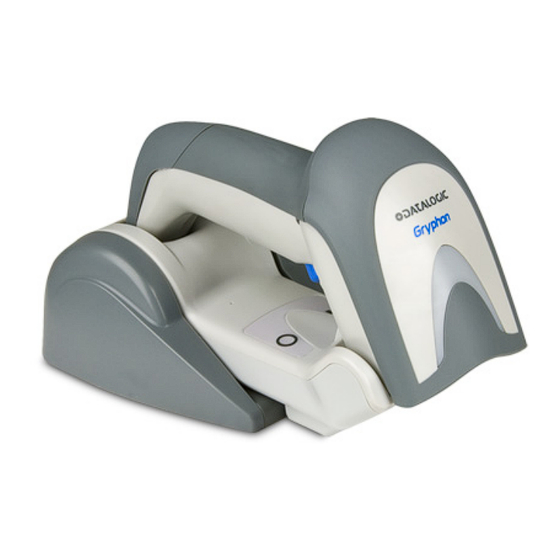
- Page 1 Gryphon™ I GM44XX General Purpose Handheld Area Imager Bar Code Reader with Datalogic’s STAR Cordless System™ Quick Reference Guide...
- Page 2 Datalogic ADC, Inc. or its subsidiaries or affiliates ("Datalogic" or “Datalogic ADC”). Owners of Datalogic...
-
Page 3: Table Of Contents
Battery Safety ................... 11 Replacing the Batteries ..............13 Using the Gryphon™ I GM44XX ............15 Linking the Reader ..................16 Link Datalogic RF Devices to Base ......... 16 Power Off ...................... 16 Selecting the Interface Type ..............17 Interface Selection ................. 17 Configuring the Interface .......... - Page 4 Canadian Notice..............44 Power Supply ................... 45 Imager Labeling ................48 Aiming System..............48 WEEE Statement ................53 Datalogic ADC Limited Factory Warranty ......54 Warranty Coverage ............. 54 Warranty Claims Process........... 54 Warranty Exclusions............55 No Assignment ..............56 Risk of Loss ................
-
Page 5: End User License Agreement
Agreement. If you do not intend to be bound to the terms of this Agreement, Datalogic is not willing to license the Software to you, you may not use the Datalogic Product or the Software, and you must contact the party from whom you acquired the Datalogic Product for instructions. -
Page 6: Limited Warranty
End User shall not sell, assign, sublicense, distribute, lend, rent, give, or other- wise transfer the Datalogic Product to any third party unless such third party agrees with Datalogic in writing to be bound by the terms and conditions of this Agreement. Any such transfer of the Datalogic Product absent such agree- ment shall be null and void. -
Page 7: Limitation Of Liability
Datalogic ADC, Inc., Legal Department, 959 Terry Street, Eugene, OR 97402. In the defense or settlement of any such claim, Datalogic may, at its option, 1) procure for End User the right to continue using the Datalogic Product, 2) -
Page 8: Software Product Policy
- END - Software Product Policy Datalogic reserves the right to ship its products with the latest version of software/ firmware available. This provides our customers with the very latest in Datalogic soft- ware technology. -
Page 9: Description
Gryphon™ I GM44XX Description With rich feature sets and extensive options, the Gryphon™ product series from Datalogic represents the premium level of data collection equipment for general purpose applications. The Gryphon GM44XX readers have enhanced optics with improved motion tolerance allowing codes placed on fast... -
Page 10: Setting Up The Reader
Setting Up the Reader Setting Up the Reader Follow the steps below to connect and get your reader up and communicating with its host. Configure the Base Station starting on this page. Charge the Batteries (see page 11). Link to the Base Station (see page 16). Select the Interface Type (see page 17). -
Page 11: Changing The Base Station Position
Setting Up the Reader Changing the Base Station Position A tool such as a rigid pen or a flat screwdriver can be used to change the mounts. Do not allow the tool to touch the contacts. The base station is configured by installing one of two sets of mechanical parts that come with the cordless kit. - Page 12 Setting Up the Reader Using your thumbs, push open the plastic tabs on the bottom of the base to free the wing holders. Figure 3. Tabs The stand can now be repositioned in either horizon- tal or standing position. Figure 4. Stand positions Horizontal Standing Gryphon™...
-
Page 13: Connecting The Base Station
(if necessary) be- fore proceeding. Connect the interface cable before applying power to the Base Station. The Gryphon GM44XX can also be Powered by the Terminal. When powered by the Terminal, the battery charger is automatically set as Slow charge. - Page 14 Connecting the Base Station Figure 6. Options for routing the DC cord Please refer to the arrows depicted on the bottom of the base when placing the cables, detailed in Figure 7 Figure 7. Arrows showing routing Verify before connection that the reader’s ca- Host Connection: ble type is compatible with your host equipment.
- Page 15 Connecting the Base Station Figure 8. Connecting to the Host or... or... or... Plug the AC Adapter into an approved AC Power Connection: wall socket with the cable facing downwards (as shown in Fig- ) to prevent undue strain on the socket. ure 5 To detach the cable, insert a paper clip Disconnecting the Cable:...
-
Page 16: System And Network Layouts
Connecting the Base Station System and Network Layouts Stand Alone Layouts Figure 10. Single Reader Layout Figure 11. Multiple Reader Layout In stand alone systems, each cradle is connected to a single Host. Figure 12. Multiple Stand Alone Layouts Gryphon™ I GM44XX... -
Page 17: Using The Bc40Xx™ Radio Base
Connecting the Base Station Many stand alone connections can operate in the same physi- cal area without interference, provided all readers and cradles in the system have different addresses. Using the BC40xx™ Radio Base Radio Base LEDs LEDs on the Gryphon Base provide information about the Base as well as battery charging status, as shown in Figure 13 Figure 13. -
Page 18: Cleaning
Connecting the Base Station Cleaning Exterior surfaces and scan windows exposed to spills, smudges or debris require periodic cleaning to ensure best performance during scanning. Contacts on the scanner and base should also be cleaned as needed to ensure a good connection. Use a soft, dry cloth to clean the product. -
Page 19: Charging The Batteries
) will indicate the sta- Table 1 tus of the battery. Before using the Battery, read “Battery Safety” in the follow- ing section. Datalogic recommends annual replacement of rechargeable battery packs to ensure maximum perfor- mance. Battery Safety To install, charge and/or perform any other action on the bat- tery, follow the instructions in this manual. - Page 20 Always charge the battery at 32° – 104°F (0° - 40°C) tem- perature range. Use only the authorized power supplies, battery pack, chargers, and docks supplied by your Datalogic reseller. CAUTION The use of any other power supplies can damage the device and void your warranty.
-
Page 21: Replacing The Batteries
US and China regulatory and other laws and regulations about the environment. Replacing the Batteries Before proceeding, read “Battery Safety” on the preced- ing pages. Datalogic recommends annual replacement of rechargeable battery packs to ensure maximum perfor- mance. Use the following procedure to change the reader’s battery: With a screwdriver, unscrew the battery cover screw. - Page 22 Charging the Batteries Unplug the white connector, and remove the two screws securing the battery holder. Connector Screw Screw Carefully lift out the gold contacts circuit, and remove the battery holder cap while letting the white connec- tor pass through the hole in the battery holder (as shown below).
-
Page 23: Using The Gryphon™ I Gm44Xx
LED indicator. Reference the Gryphon I 44XX Product Reference Guide (PRG) or Datalogic Aladdin configuration software (both available on the Datalogic website) for more information about this feature and other programmable settings. Quick Reference Guide... -
Page 24: Linking The Reader
Linking the Reader Linking the Reader Link Datalogic RF Devices to Base For RF devices, before configuring the interface it is necessary to link the handheld with the base. To link the handheld and the base, either press the trigger to wake it, or simply mount into the base to wake up for opera- tion. -
Page 25: Selecting The Interface Type
Selecting the Interface Type Selecting the Interface Type Upon completing the physical connection between the reader and its host, proceed directly to Interface Selection (below) for information and programming for the interface type the read- er is connected to (for example: RS-232, Keyboard Wedge, USB, etc.) and scan the appropriate bar code to select your sys- tem’s correct interface type. - Page 26 Selecting the Interface Type RS-232 RS-232 standard interface Select RS232-STD RS-232 Wincor-Nixdorf Select RS232-WN RS-232 for use with OPOS/UPOS/JavaPOS Select RS-232 OPOS USB COM to simulate RS-232 standard interface Select USB-COM-STD a. Download the correct USB COM driver from www.datalogic.com Gryphon™ I GM44XX...
- Page 27 Selecting the Interface Type IBM-46xx Port 5B reader interface Select IBM-P5B IBM-46xx Port 9B reader interface Select IBM-P9B USB-OEM USB-OEM (can be used for OPOS/UPOS/JavaPOS) Select USB-OEM Quick Reference Guide...
-
Page 28: Keyboard Interface
Selecting the Interface Type Keyboard Interface Use the programming bar codes to select options for USB Keyboard and Wedge Interfaces. KEYBOARD AT, PS/2 25-286, 30-286, 50, 50Z, 60, 70, 80, 90 & 95 w/ Standard Key Encoding Select KBD-AT Keyboard Wedge for IBM AT PS2 with standard key encoding but without external keyboard Select KBD-AT-NK AT, PS/2 25-286, 30-286, 50, 50Z, 60, 70, 80, 90 &... - Page 29 Selecting the Interface Type KEYBOARD (continued) PC/XT w/Standard Key Encoding Select KBD-XT Keyboard Wedge for IBM Terminal 3153 Select KBD-IBM-3153 Keyboard Wedge for IBM Terminals 31xx, 32xx, 34xx, 37xx make only keyboard Select KBD-IBM-M Keyboard Wedge for IBM Terminals 31xx, 32xx, 34xx, 37xx make break keyboard Select KBD-IBM-MB USB Keyboard with alternate key encoding...
-
Page 30: Scancode Tables
Selecting the Interface Type KEYBOARD (continued) Keyboard Wedge for DIGITAL Terminals VT2xx, VT3xx, VT4xx Select KBD-DIG-VT USB Keyboard with standard key encoding Select USB Keyboard WAND EMULATION Wand Emulation Select WAND Scancode Tables Reference the Gryphon™ PRG for information about control character emulation which applies to keyboard interfaces. - Page 31 Selecting the Interface Type COUNTRY MODE ENTER/EXIT PROGRAMMING MODE Country Mode = U.S. Country Mode = Belgium Country Mode = Britain Country Mode = Croatia* *Supports only the interfaces listed in the Country Mode feature description Quick Reference Guide...
- Page 32 Selecting the Interface Type COUNTRY MODE (continued) Country Mode = Czech* Country Mode = Denmark* Country Mode = France Country Mode = Germany Country Mode = Hungary* Country Mode = Italy *Supports only the interfaces listed in the Country Mode feature description Gryphon™...
- Page 33 Selecting the Interface Type COUNTRY MODE (continued) Country Mode = Japanese 106-key* Country Mode = Norway* Country Mode = Poland* Country Mode = Portugal* Country Mode = Romania* Country Mode = Spain *Supports only the interfaces listed in the Country Mode feature description Quick Reference Guide...
- Page 34 Selecting the Interface Type COUNTRY MODE (continued) Country Mode = Sweden Country Mode = Slovakia* Country Mode = Switzerland* *Supports only the interfaces listed in the Country Mode feature description Gryphon™ I GM44XX...
-
Page 35: Caps Lock State
Selecting the Interface Type Caps Lock State This option specifies the format in which the reader sends character data. This applies to keyboard wedge interfaces. This does not apply when an alternate key encoding keyboard is se- lected. ENTER/EXIT PROGRAMMING MODE Caps Lock State = Caps Lock OFF Caps Lock State = Caps Lock ON Caps Lock State = AUTO Caps Lock Enable... -
Page 36: Numlock
Selecting the Interface Type Numlock This option specifies the setting of the Numbers Lock (Num- lock) key while in keyboard wedge interface. This only applies to alternate key encoding interfaces. It does not apply to USB keyboard. ENTER/EXIT PROGRAMMING MODE Numlock = Numlock key unchanged Numlock = Numlock key toggled Gryphon™... -
Page 37: Programming
Programming Programming The reader is factory-configured with a set of standard default features. After scanning the interface bar code from the Inter- faces section, select other options and customize your reader through use of the programming bar codes available in the Product Reference Guide (PRG). -
Page 38: Reading Parameters
Reading Parameters Reading Parameters Point the reader at the target and pull the trigger to enable the aiming system and the illuminator (red beam) to capture and decode the image. The aiming system will briefly switch off during the acquisition time and if no code is decoded will switch on again before the next acquisition. -
Page 39: Good Read Green Spot Duration
Reading Parameters Good Read Green Spot Duration Successful reading can be signaled by a good read green spot. Use the bar codes below to specify the duration of the good read pointer beam after a good read. ENTER/EXIT PROGRAMMING MODE Green Spot Duration = Disable (Green Spot is Off) Green Spot Duration = Short (300 msec) Green Spot Duration = Medium (500 msec) -
Page 40: Scan Modes
Scan Modes Scan Modes The imager can operate in one of several scanning modes. When the trigger is pulled, scanning is activat- Trigger Single — ed until one of the following occurs: - a programmable duration has elapsed - a label has been read - the trigger is released This mode is associated with typical handheld reader opera- tion. - Page 41 Scan Modes SCAN MODE ENTER/EXIT PROGRAMMING MODE Scan Mode = Trigger Single Scan Mode = Trigger Hold Multiple Scan Mode = Trigger Pulse Multiple Scan Mode = Flashing Scan Mode = Always On Scan Mode = Stand Mode Quick Reference Guide...
-
Page 42: Pick Mode
Scan Modes Pick Mode Pick Mode is a Decoding and Transmission process where bar codes that are not within the configurable distance from the center of the aiming pattern are not acknowledged or trans- mitted to the host. It is active only while the scanner is in Trig- ger Single mode. -
Page 43: Technical Specifications
Technical Specifications Technical Specifications The following table contains Physical and Performance Char- acteristics, User Environment and Regulatory information. Physical Characteristics White/Gray Color Black/Gray Height 7.1”/181 mm Dimensions Length 3.9”/100 mm Width 2.8”/71 mm Approximately Weight (without cable) 8.7 ounces/246 g (reader with display) 8.7 ounces/246 g (base charger) Electrical Characteristics Battery Type... - Page 44 Technical Specifications Depth of Field (Typical) Symbology 5mil: 1.6” -7.5” (4.0 -19cm) Code 39 10mil: 0.4” - 11.8” (1.0 - 30cm) 20mil: up to 17.7” (up to 45cm) 7.5mil: 0.5” - 10.6” (2.0 - 27cm) 13mil: 0.6” - 15.7” (1.5 - 40cm) 6.6mil: 1.0”...
- Page 45 PPT; Code 32 (Italian Pharmacode 39); Code 128; Code 128 ISBT; Interleaved 2 of 5; Standard 2 of 5; Interleaved 2 of 5 CIP (HR); Industrial 2 of 5; Discrete 2 of 5; Datalogic 2 of 5 (China Post Code/Chinese 2 of 5); IATA 2of5 Air cargo code; Code 11; Codabar; Codabar (NW7); ABC Cod- abar;...
- Page 46 Technical Specifications User Environment (continued) Scanner withstands 18 drops from 1.8 meters Drop Specifications (5.9 feet) to concrete Ambient Light Immunity Up to 100,000 Lux Contaminants Spray/rain IEC 529-IP52 (scanner only) Dust/particulates ESD Level 16 KV Regulatory Electrical Safety UL 60950, CSA C22.2 No. 60950, IEC 60950 433 MHz model 910 MHz model Europe - CE, Russia –...
-
Page 47: Led And Beeper Indications
LED and Beeper Indications LED and Beeper Indications The reader’s beeper sounds and its LED illuminates to indicate various functions or errors on the reader. An optional “Green Spot” also performs useful functions. The following tables list these indications. One exception to the behaviors listed in the tables is that the reader’s functions are programmable, and so may or may not be turned on. -
Page 48: Programming Mode
LED and Beeper Indications Indication Description Beeper Upon successful read of a label, the soft- Green Spot ware shall turn the flashes green spot on for the momentarily time specified by the configured value. Blue light flashes Image When ready to cap- 2 times when Capture ture image... -
Page 49: Error Codes
Error Codes INDICATION DESCRIPTION BEEPER Reader sounds Label Programming Cancel label has been two times at low Mode Cancel Item scanned. frequency and Entry current volume. Error Codes Upon startup, if the reader sounds a long tone, this means the reader has not passed its automatic Selftest and has entered FRU (Field Replaceable Unit) isolation mode. -
Page 50: Base Station Indications
Base Station Indications Base Station Indications Indication LEDS Power-up Complete Yellow LED on Reader Disabled by the HOST or the communication with HOST is Yellow LED blinking ~1Hz not established Data/labels are transmitted to the Yellow LEDs turned off HOST for 100mSec Programming Mode Yellow LED blinks quickly... -
Page 51: Regulatory Information
Any changes or modifications to equipment, not expressly ap- proved by Datalogic could void the user's authority to operate the equipment. Statement of Agency Compliance This device complies with part 15 of the FCC Rules. -
Page 52: Fcc Rf Radiation Exposure Statement
Regulatory Information FCC RF Radiation Exposure Statement This equipment complies with FCC radiation exposure limits under Specific Absorption Rate (SAR) tests for portable devic- es operating closer than 20 cm to nearby persons, set forth in an uncontrolled environment. The Gryphon M44XX cordless imaging reader has been demonstrated to meet these RF emis- sions safety limits. -
Page 53: Power Supply
Regulatory Information Power Supply This device is intended to be connected to a UL Listed/CSA Certified computer which supplies power directly to the read- er or else be supplied by UL Listed/CSA Certified Power Unit marked “Class 2” or LPS power source rated 5-14V minimum 900mA, which supplies power directly to the Base/Charger via the power connector of the Base itself. - Page 54 Regulatory Information China RoHS Table of Restricted Elements (Scanner) Gryphon™ I GM44XX...
- Page 55 Regulatory Information China RoHS Table of Restricted Elements (Base) Quick Reference Guide...
-
Page 56: Imager Labeling
Regulatory Information Imager Labeling Sample labels are shown for illustrative purposes only. Please view the labels on your product for actual details, as they may vary from those depicted. Scanner Regulatory Label Base Station Label 239045 PATENTS PENDING Aiming System ™... - Page 57 Regulatory Information LE RAYON LA LUCE DIE LASER- LASER EST LASER È VISI- A LUZ LÁSER STRAHLUNG IST VISIBLE À BILE ES VISIBLE AL FÜR DAS MEN- L'OEIL NU ET ALL'OCCHIO SCHLICHE AUGE IL EST ÉMIS UMANO E HUMANO Y SICHTBAR UND PAR LA VIENE...
- Page 58 Regulatory Information For installation, use and maintenance, it is not necessary to open the device. Use of controls or adjustments or performance of proce- dures other than those specified herein may result in expo- sure to hazardous visible laser light. WARNING The product utilizes a low-power laser diode.
- Page 59 Regulatory Information NORM FÜR DIE LASERSICHERHEIT Dies Produkt entspricht am Tag der Herstellung den gültigen EN 60825-1 und CDRH 21 CFR 1040 Normen für die La- sersicherheit. Es ist nicht notwendig, das Gerät wegen Betrieb oder Installa- tions-, und Wartungs-Arbeiten zu öffnen. Jegliche Änderungen am Gerät sowie Vorgehensweisen, die nicht in dieser Betriebsanleitung beschreiben werden, können ein gefährliches Laserlicht verursachen.
- Page 60 Regulatory Information ESPAÑOL Las informaciones siguientes son presentadas en conformidad con las disposiciones de las autoridades internacionales y se re- fieren al uso correcto del terminal. NORMATIVAS ESTÁNDAR PARA LA SEGURIDAD LÁSER Este aparato resulta conforme a las normativas vigentes de se- guridad láser a la fecha de producción: CDRH 21 CFR 1040 y EN 60825-1.
-
Page 61: Weee Statement
Spanish Si desea información acerca de los procedimientos para el desecho de los residuos del equipo eléctrico y electrónico (WEEE), visite la página Web www.datalogic.com. Portuguese Para informações sobre a disposição de Sucatagem de Equipamentos Elétricos e Eletrônicos (WEEE -Waste Electrical and Electronic Equipment), consultar o site web www.datalogic.com. -
Page 62: Datalogic Adc Limited Factory Warranty
If Datalogic determines that a product has defects in material or workmanship, Datalogic shall, at its sole option repair or re- place the product without additional charge for parts and la- bor, or credit or refund the defective products duly returned to Datalogic. -
Page 63: Warranty Exclusions
Customer shall be responsible for packaging and ship- ping the product to the designated Datalogic service center, with shipping charges prepaid. Datalogic shall pay for the re- turn of the product to Customer if the shipment is to a loca- tion within the country in which the Datalogic service center is located. -
Page 64: No Assignment
Risk of Loss Customer shall bear risk of loss or damage for product in tran- sit to Datalogic. Datalogic shall assume risk of loss or damage for product in Datalogic’s possession. In the absence of specific written instructions for the return of product to Customer,... -
Page 65: Ergonomic Recommendations
Provide adequate clearance • Provide a suitable working environment • Improve work procedures. Services and Support Datalogic provides several services as well as technical support through its website. Log on to and click www.datalogic.com on the links indicated for further information. Products... - Page 66 Services and Support NOTES Gryphon™ I GM44XX...
-
Page 67: Declaration Of Conformity
La presente dichiarazione di conformità è rilasciata sotto la responsabilità esclusiva di Datalogic ADC Srl per: This Declaration of Conformity is issued under the sole responsibility of Datalogic ADC Srl for: Cette déclaration de conformité est établie sous la seule responsabilité de Datalogic Srl pour: Diese Konformitätserklärung wird unter der alleinigen Verantwortung des Datalogic ADC Srl... - Page 68 ©2011-2013 Datalogic ADC, Inc. • All rights reserved. Datalogic and the Datalogic logo are registered trademarks of Datalogic S.p.A. in many countries, including the U.S.A. and the E.U. Datalogic ADC, Inc. 959 Terry Street Eugene |OR 97402 Telephone: (1) 541-683-5700...
Need help?
Do you have a question about the Gryphon GM44XX and is the answer not in the manual?
Questions and answers