
Related Manuals for Datalogic Gryphon GM4102


Summary of Contents for Datalogic Gryphon GM4102
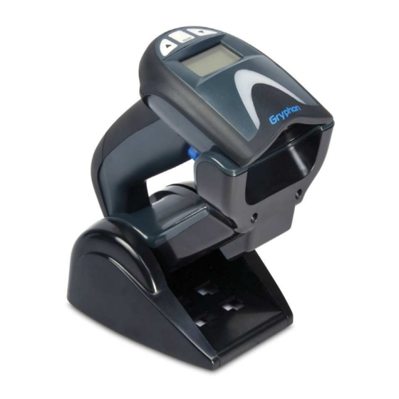
- Page 1 Gryphon™ I GM4102 General Purpose Handheld Linear Imager Barcode Reader with Datalogic’s STAR Cordless System™ BSR idware GmbH Jakob-Haringer-Str.3 A-5020 Salzburg https://www.bsr.at sales@bsr.at Quick Reference Guide...
- Page 2 Datalogic USA Inc. or its subsidiaries or affiliates (“Datalogic” or “Datalogic USA”). Owners of Datalogic products are hereby granted a non-exclusive, revocable license to reproduce and transmit this documentation for the purchaser's own internal business purposes.
-
Page 3: Table Of Contents
Ergonomic Recommendations ..........36 Cleaning Procedure ..............37 Common Cleaning Solutions ..........37 Cleaning enclosure and window surfaces ....... 38 Cleaning electrical contact surfaces ........ 38 Datalogic Limited Factory Warranty ........ 39 Warranty Coverage ........... 39 Warranty Claims Process......... 39 Quick Reference Guide... - Page 4 Warranty Exclusions..........40 No Assignment ............40 Risk of Loss ............... 41 Support Through the Website ........... 42 Gryphon™ I GM4102...
- Page 5 This End User License Agreement ("EULA") is between Datalogic IP Tech S.r.l. having its registered office at Via San Vitalino 13, 40012 Calderara di Reno (Bologna), Italy ("Datalogic"), and you, either an individual or a single entity, ("End User or "You"") who has purchased one or more Gry- phon I GM4102 ("Datalogic Product") subject to the terms and condi-...
- Page 6 (additional) license fees due and any further damages, if any. 2. License Fee License fees shall be due by End User to Datalogic according to the terms provided for in the relevant contract for the purchase of the Datalogic Product.
- Page 7 Rights in Technical Data and Computer Software clause at DFARS 252.227-7013(c)(1)(ii), whichever is applicable. If End User is using the Datalogic Product outside of the United States, End User must comply with the applicable local laws of the country in which the Datalogic Product is used and with U.S.
- Page 8 State of Oregon located in either Multnomah or Lane counties shall have exclusive jurisdiction over all matters regard- ing this Agreement, except that Datalogic shall have the right, at its absolute discretion, to initiate proceedings in the courts of any other state, country, or territory in which End User resides, or in which any of End User' s assets are located.
-
Page 9: Software Product Policy
- END - Software Product Policy Datalogic reserves the right to ship its products with the latest version of software/firmware available. This provides our customers with the very latest in Datalogic software technology. The only exception to this policy is when the buyer has a signed contract with Datalogic that clearly defines the terms and conditions for making software/firmware changes in products shipped to the buyer. - Page 10 Software Product Policy NOTES viii Gryphon™ I GM4102...
-
Page 11: Setting Up The Reader
Gryphon™ I GM4102 Quick Reference Guide Setting Up the Reader Follow the steps below to connect and get your reader up and communicating with its host. Configure the Base Station starting on this page. Charge the Batteries (see page 8). Link to the Base Station (see page 13). -
Page 12: Changing The Base Station Position
Configure the Base Station Changing the Base Station Position The base station is configured by installing one of two sets of mechanical parts that come with the cordless kit. The default mounts (shown below) provide three options: vertical (wall) mounting, standing (45°), or horizontal mounting with a higher mechanical retention of the scan- ner. - Page 13 Configure the Base Station To ensure best contact and performance, do not intermix the parts of the two different mount sets. CAUTION The stand can now be repositioned in either horizontal or standing position. Horizontal Standing Quick Reference Guide...
-
Page 14: Connecting The Base Station
(if necessary) before proceeding. Connect the interface cable before applying power to the Base Station. The Gryphon GM4102 can also be Powered by the Terminal. When powered by the Terminal, the battery charger is automatically set as Slow charge. -
Page 15: Securing The Dc Power Cord (Optional)
Configure the Base Station Securing the DC Power Cord (Optional) The DC power cord for the adapter can be secured to the bottom of the base in order to maximize the mechanical retention of the cable itself. The routing of the power cord can be changed to accommodate the base station posi- tioning: horizontal, stand or wall mounting. - Page 16 Configure the Base Station Host Connection — Verify before connection that the reader’s cable type is compatible with your host equip- ment. Most connections plug directly into the host device as shown in Figure 4 on page 6. Keyboard Wedge interface cables have a ‘Y’...
-
Page 17: Using The Bc40Xx™ Radio Base
Base. A button is available to force device connection via the Datalogic Aladdin Software tool, and for paging the scan- ner when bidirectional connection is activated. Refer to the Gryphon I Product Reference Guide (PRG) for a more detailed explanation. -
Page 18: Charging The Batteries
When the scanner is fully seated in the cradle, it will sound a “chirp” to indicate that the cradle has detected the scanner connection. Before using the Battery, read “Battery Safety” in the following section. Datalogic recom- mends annual replacement of rechargeable battery packs to ensure maximum perfor- mance. - Page 19 Use only the authorized power supplies, bat- tery pack, chargers, and docks supplied by your CAUTION Datalogic reseller. The use of any other power supplies can damage the device and void your warranty. Do not disassemble or modify the battery. The...
- Page 20 Charging the Batteries As with other types of batteries, Lithium-Ion (LI) batteries will lose capacity over time. Capacity deterioration is noticeable after one year of service whether the battery is in use or not. It is difficult to precisely predict the finite life of a LI battery, but cell manufacturers rate them at 500 charge cycles.
-
Page 21: Replacing The Batteries
Charging the Batteries Replacing the Batteries Before proceeding, read “Battery Safety” on the preceding pages. Datalogic recommends annual replacement of rechargeable battery packs to ensure maximum performance. Use the following procedure to change the reader’s bat- tery: With a screwdriver, unscrew the battery cover screw. - Page 22 Charging the Batteries Carefully lift out the gold contacts circuit, and remove the battery holder while letting the white connector pass through the hole in the battery holder (as shown below). Pass-through hole Gold contacts circuit Remove the old battery from its place (if pres- ent), and insert the new battery in the same position.
-
Page 23: Linking The Reader To A Base Station
Linking the Reader to a Base Station Linking the Reader to a Base Station RF Devices For RF devices, before configuring the interface it is nec- essary to link the handheld with the base. To link the handheld and the base, press the trigger to wake it and place it on the base. - Page 24 System and Network Layouts Figure 8. Multiple Reader Layout In stand alone systems, each cradle is connected to a sin- gle Host. Figure 9. Multiple Stand Alone Layouts Many stand alone connections can operate in the same physical area without interference, provided all readers and cradles in the system have different addresses.
-
Page 25: Select The Interface Type
Select the Interface Type Select the Interface Type Upon completing the physical connection between the reader and its host, proceed directly to Interface Selection on page 15 for information and programming for the interface type the reader is connected to (for example: RS- 232, Keyboard Wedge, USB, etc.) and scan the appropriate barcode to select your system’s correct interface type. - Page 26 Select the Interface Type RS-232 RS-232 standard interface Select RS232-STD RS-232 Wincor-Nixdorf Select RS232-WN RS-232 for use with OPOS/UPOS/JavaPOS Select RS-232 OPOS USB Com to simulate RS-232 standard interface Select USB-COM-STD Gryphon™ I GM4102...
- Page 27 IBM (available with accessory cable) IBM-46xx Port 5B reader interface Select IBM-P5B IBM-46xx Port 9B reader interface Select IBM-P9B USB-OEM USB-OEM (can be used for OPOS/UPOS/JavaPOS) Select USB-OEM a. Download the correct USB Com driver from www.datalogic.com Quick Reference Guide...
- Page 28 Select the Interface Type KEYBOARD AT, PS/2 25-286, 30-286, 50, 50Z, 60, 70, 80, 90 & 95 w/ Standard Key Encoding Select KBD-AT Keyboard Wedge for IBM AT PS2 with standard key encoding but without external keyboard Select KBD-AT-NK AT, PS/2 25-286, 30-286, 50, 50Z, 60, 70, 80, 90 & 95 w/Alternate Key Select KBD-AT-ALT Keyboard Wedge for IBM AT PS2 with alternate key encoding...
- Page 29 Select the Interface Type KEYBOARD (continued) PC/XT w/Standard Key Encoding Select KBD-XT Keyboard Wedge for IBM Terminal 3153 Select KBD-IBM-3153 Keyboard Wedge for IBM Terminals 31xx, 32xx, 34xx, 37xx make only keyboard Select KBD-IBM-M Keyboard Wedge for IBM Terminals 31xx, 32xx, 34xx, 37xx make break keyboard Select KBD-IBM-MB Quick Reference Guide...
-
Page 30: Wand Emulation
Select the Interface Type KEYBOARD (continued) Keyboard Wedge for DIGITAL Terminals VT2xx, VT3xx, VT4xx Select KBD-DIG-VT USB Keyboard with standard key encoding Select USB Keyboard USB Keyboard with alternate key encoding Select USB Alternate Keyboard USB Keyboard for Apple computers Select USB-KBD-APPLE WAND EMULATION Wand Emulation... -
Page 31: Keyboard Interface
Keyboard Interface Keyboard Interface Use the programming barcodes to select options for USB Keyboard and Wedge Interfaces. Standard Factory Settings Reference the Gryphon™ I GD4132/GM4102 Product Ref- erence Guide (PRG) for a listing of standard factory set- tings. Scancode Tables Reference the Gryphon™... - Page 32 Country Mode COUNTRY MODE ENTER/EXIT PROGRAMMING MODE Country Mode = U.S. Country Mode = Belgium Country Mode = Britain Country Mode = Croatia* Country Mode = Czech Republic* *Supports only the interfaces listed in the Country Mode feature descrip- tion Gryphon™...
- Page 33 Country Mode COUNTRY MODE (continued) Country Mode = Denmark* Country Mode = France Country Mode = French Canadian Country Mode = Germany Country Mode = Hungary* *Supports only the interfaces listed in the Country Mode feature descrip- tion Quick Reference Guide...
- Page 34 Country Mode COUNTRY MODE (continued) Country Mode = Italy Country Mode = Japanese 106-key* Country Mode = Lithuanian Country Mode = Norway* Country Mode = Poland* Country Mode = Portugal* *Supports only the interfaces listed in the Country Mode feature descrip- tion Gryphon™...
- Page 35 Country Mode COUNTRY MODE (continued) Country Mode = Romania* Country Mode = Slovakia* Country Mode = Spain Country Mode = Sweden Country Mode = Switzerland* *Supports only the interfaces listed in the Country Mode feature descrip- tion Quick Reference Guide...
-
Page 36: Caps Lock State
Caps Lock State Caps Lock State This option specifies the format in which the reader sends character data. This applies to keyboard wedge interfaces. This does not apply when an alternate key encoding key- board is selected. ENTER/EXIT PROGRAMMING MODE Caps Lock State = Caps Lock OFF Caps Lock State = Caps Lock ON Caps Lock State = AUTO Caps Lock Enable... -
Page 37: Numlock
Numlock Numlock This option specifies the setting of the Numbers Lock (Numlock) key while in keyboard wedge interface. This only applies to alternate key encoding interfaces. It does not apply to USB keyboard. ENTER/EXIT PROGRAMMING MODE Numlock = Numlock key unchanged Numlock = Numlock key toggled Programming The reader is factory-configured with a set of standard... -
Page 38: Using The Programming Barcodes
Programming Using the Programming Barcodes This manual contains barcodes which allow you to recon- figure your reader. Some programming barcode labels, like Standard Product Default Settings on page 28, require only the scan of that single label to enact the change. Other barcodes require the reader to be placed in Pro- gramming Mode prior to scanning them. -
Page 39: Technical Specifications
Technical Specifications Technical Specifications The following table contains Physical and Performance Characteristics, User Environment and Regulatory infor- mation. Item Description Physical Characteristics White/Gray Color Black/Gray Height 7.1”/181 mm Dimensions Length 3.9”/100 mm Width 2.8”/71 mm Approximately Weight (without 8.7 ounces/246 g cable) 9.7 ounces/275 g (base charger) Electrical Characteristics... - Page 40 Technical Specifications Item Description 3 mil – 2.9” to 4.7” (7.5cm to 12cm) Depth of Field (Typi- 13 mil – 1.2” to 23.6” (3cm to 60cm) cal) 20 mil – 1.2” to 31.5” (3cm to 80cm) Minimum Element 3 mil Width Print Contrast Mini- 15% minimum reflectance...
- Page 41 Technical Specifications Item Description Regulatory See the Regulatory Addendum. Radio Features 433MHz model 910MHz model Working Center Fre- 433.920 MHz 910.000 MHz quency Range (in open air) 30 m System Configuration 433MHz model 910MHz model Max. number of devices per base sta- tion Quick Reference Guide...
-
Page 42: Led And Beeper Indications
LED and Beeper Indications LED and Beeper Indications The reader’s beeper sounds and its LED illuminates to indicate various functions or errors on the reader. An optional “Green Spot” also performs useful functions. The following tables list these indications. One exception to the behaviors listed in the tables is that the reader’s func- tions are programmable, and may or may not be turned on. - Page 43 LED and Beeper Indications INDICATION DESCRIPTION BEEPER The reader has The LED Reader been disabled blinks contin- Disabled by the host. uously While in Stand Mode or Trig- Green Spot is ger Stand Mode on continu- the green spot ously shall be on while in stand watch state.
-
Page 44: Error Codes
Error Codes INDICATION DESCRIPTION BEEPER Configuration option(s) have Reader sounds been success- Label Pro- one high fre- fully pro- gramming quency beep grammed via Mode Accep- and 4 low fre- labels and the tance of Pro- quency beeps reader has gramming followed by exited Pro-... -
Page 45: Base Station Indications
Base Station Indications Base Station Indications INDICATION LEDS Power-up Complete Yellow LED on Reader Disabled by the HOST or Yellow LED blinking the communication with HOST is ~1Hz not established Data/labels are transmitted to Yellow LEDs turned off the HOST for 100mSec Yellow LED blinks Programming Mode... -
Page 46: Ergonomic Recommendations
Ergonomic Recommendations Ergonomic Recommendations To avoid or minimize the potential risk of ergonomic injury follow the recommenda- tions below. Consult with your local Health & Safety Manager to ensure that you are adher- ing to your company’s safety programs to CAUTION prevent employee injury. -
Page 47: Cleaning Procedure
Be sure to turn off power and unplug the device from electrical outlet before cleaning. CAUTION Common Cleaning Solutions The cleaners and disinfectants listed below are recom- mended for use on Datalogic’s Disinfectant-Ready Enclo- sures: Cleaners Disinfectants Formula 409® Glass and surface CaviWipes™... -
Page 48: Cleaning Enclosure And Window Surfaces
Cleaning Procedure Cleaning enclosure and window surfaces Moisten a soft cloth with a recommended cleaning solution. Be sure to apply the solution to your cloth first. Wring excessive liquid from the cloth. Use the cloth to wipe down the surface of the unit. Use cotton swabs, lightly moistened, to reach in corners and crevices. -
Page 49: Datalogic Limited Factory Warranty
Datalogic hardware products are warranted against defects in material and workmanship under normal and proper use. The liability of Datalogic under this warranty is limited to furnish- ing the labor and parts necessary to remedy any defect cov- ered by this warranty and restore the product to its normal operating condition. -
Page 50: Warranty Exclusions
Datalogic shall pay for the return of the product to Customer if the shipment is to a loca- tion within the country in which the Datalogic service center is located. Customer shall be responsible for paying all shipping charges, duties, taxes, and any other charges for products returned to any other locations. -
Page 51: Risk Of Loss
Risk of Loss Customer shall bear risk of loss or damage for product in transit to Datalogic. Datalogic shall assume risk of loss or damage for product in Datalogic’s possession. In the absence of specific written instructions for the return of product to... -
Page 52: Support Through The Website
Support Through the Website Support Through the Website Datalogic provides several services as well as technical support through its website. Log on to www.datalogic.com and click on the SUPPORT link which gives you access to: • Downloads by selecting your product model from the dropdown list in the Search by Product field for spe- cific Data Sheets, Manuals, Software &... - Page 53 Support Through the Website NOTES Quick Reference Guide...
- Page 54 Support Through the Website NOTES Gryphon™ I GM4102...
- Page 56 ©2009-2018 Datalogic S.p.A. and/or its affiliates. All rights reserved. Datalogic and the Datalogic logo are registered trademarks of Datalogic S.p.A. in many countries, including the U.S. and the E.U. Datalogic USA Inc. 959 Terry Street | Eugene, OR 97402 | U.S.A. |...
Need help?
Do you have a question about the Gryphon GM4102 and is the answer not in the manual?
Questions and answers