Table of Contents
Advertisement
Quick Links
Advertisement
Table of Contents

Related Manuals for Dahua 32 Series


Summary of Contents for Dahua 32 Series
-
Page 1: Quick Start Guide
Network Video Recorder Quick Start Guide Version 1.3.0... -
Page 2: Table Of Contents
1.1 Check Unpacked NVR ..................1 1.2 About Front Panel and Rear Panel..............1 1.3 After Remove the Chassis..................1 1.4 HDD Installation .....................1 1.4.1 32 Series/32-P Series/32-S Series............1 1.4.2 38 Series.......................2 1.5 Front Panel ......................3 1.5.1 32 Series/32-P Series/32-S Series............3 1.5.2 38 Series.......................4 1.6 Rear Panel ......................6... - Page 3 3.7.2 Built-in Switch Setup.................19 3.7.3 Remote Device ..................20 Web Client Operation ....................24 4.1 Network Connection ....................24 4.2 Login ........................24 4.3 Main Window ......................24 Appendix Toxic or Hazardous Materials or Elements .............26...
- Page 4 Welcome Thank you for purchasing our network video recorder! This quick start guide is designed to be a reference tool for your system. Please open the accessory bag to check the items one by one in accordance with the list below. Contact your local retailer ASAP if something is missing or damaged in the bag.
-
Page 5: Important Safeguards And Warnings
Important Safeguards and Warnings 1.Electrical safety All installation and operation here should conform to your local electrical safety codes. We assume no liability or responsibility for all the fires or electrical shock caused by improper handling or installation. 2.Transportation security Heavy stress, violent vibration or water splash are not allowed during transportation, storage and installation. - Page 6 Accessories Check the following accessories after opening the box: Please refer to the packing list in the box * Component Name 32 Series 32-P Series 32-S Series 38 Series Quantity ■ ■ ■ ■ 7-pin SATA cable ■ ■ ■...
-
Page 7: Hardware Installation And Connection
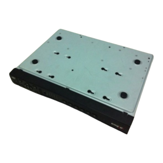
You can refer to the User’s Manual for recommended HDD brand. Please use HDD of 7200rpm or higher. Usually we do not recommend the PC HDD. Please follow the instructions below to install hard disk. 1.4.1 32 Series/32-P Series/32-S Series 1. Loosen the screws of the 2. Fix four screws in the HDD 3. -
Page 8: Series
4. Turn the device upside down 6. Connect the HDD cable and Fix the HDD firmly. and then turn the screws in power cable. firmly. 7. Put the cover in accordance 8. Secure the screws in the rear panel and the side panel. with the clip and then place the upper cover back. -
Page 9: Front Panel
Important: Please turn off the power before you replace the HDD. 1.5 Front Panel 1.5.1 32 Series/32-P Series/32-S Series The front panel is shown as in Figure 1-1. Figure 1-1 Please refer to the following sheet for front panel button information. -
Page 10: Series
Play Next In playback mode, playback the next video Up/Down Activate current control, modify setup, and then move up and down. Increase/decrease numeral. Assistant function such as PTZ menu. Left/Right Shift current activated control, and then move left and right. When playback, click these buttons to control playback bar. - Page 11 Figure 1-2 Please refer to the following sheet for front panel button information. Name Icon Function Power button, press this button for three seconds to boot up or Power button shut down DVR. Input Arabic number Number 0-9 Number button Switch channel and etc Input number...
-
Page 12: Rear Panel
If there is Fn indication light, current status indication light is null. Status light Power indication Power indication light light IR Receiver It is to receive the signal from the remote control. 1.6 Rear Panel 1.6.1 32 Series The rear panel is shown as below. See Figure 1-3. -
Page 13: 32-P Series/32-S Series
Figure 1-3 Please refer to the following sheet for detailed information. Port Name Connection Function USB port. Connect to USB mouse. Network port 10M/100M/1000M self-adaptive Ethernet port. Connect to the network cable. RS232 232 debug COM. It is for general COM debug to configure IP address or transfer transparent COM data. - Page 14 The rear panel of the 32-P series is shown as below. See Figure 1-4. Figure 1-4 The rear panel of the 32-S series is shown as below. See Figure 1-5. Figure 1-5 Please refer to the following sheet for detailed information. Port Name Connection Function USB port.
-
Page 15: Series
Port Name Connection Function C2,Group 3:port NO3~C3)).Output C1 to C3 alarm signal to the alarm device. Please make sure there is power to the external alarm device. NO:Normal open alarm output port. C:Alarm output public end. RS485 port RS485_A port. It is the cable A. You can connect to the control devices such as speed dome PTZ. - Page 16 Port Name Connection Function Power input Input AC 220V power. port MIC IN Audio input Bidirectional talk input port. It is to receive the port analog audio signal output from the devices such as mike phone, pickup. MIC OUT Audio output Audio output port.
-
Page 17: Connection Sample
Port Name Connection Function Network port 10M/100M/1000M self-adaptive Ethernet port. Connect to the network cable. eSATA eSATA port External SATA port. It can connect to the device of the SATA port. Please jump the HDD when there is peripheral connected HDD. -
Page 18: System Performance
System Performance This series product max supports 16-channel standard definition video/high definition non-real-time video and the transmission rate is 2mbps per channel. It can also max supports 4-channel high definition video and the transmission rate is 8mbps. The delay time of each channel is below 500ms. Model System Performance 4-ch series... -
Page 19: Simple Gui Operation
3 Simple GUI Operation Connect the device to the monitor and then connect a mouse and power cable. Click the power button at the rear panel and then boot up the device to view the analog video output. You can use the mouse to implement some simple GUI operation. -
Page 20: System Setting-Schedule
Figure 3-2 Important: For security reason, please modify password after you first login. Within 30 minutes, three times login failure will result in system alarm and five times login failure will result in account lock! 3.2 System Setting-Schedule After the system booted up, it is in default 24-hour regular mode. You can set record type and time in schedule interface. -
Page 21: System Setting-Network Setup
Figure 3-3 Tips Copy function: This function allows you to copy one channel setup to another. After setting in channel 1, you can click paste button and turn to channel 2 and then click copy button. You can finish setting for one channel and then click save button or you can finish all setup and then click save button to memorize all the settings. -
Page 22: System Setting-Ptz
Figure 3-4 3.4 System Setting-PTZ Please note: Slight difference may be found in the user’s interface, due to various protocols. Please make sure the speed domes A/B cables are properly connected to the A/B ports of NVR. You have properly set PTZ information.(Main menu->Setting->PTZ). Please switch camera monitor channel to current window. -
Page 23: Ptz Operation
Figure 3-5 After completing all the setups please click save button, system goes back to the previous menu. 3.4.2 PTZ Operation In one window display mode, right click mouse (click “Fn” Button in the front panel or click “Fn” key in the remote control). -
Page 24: Advanced-Hdd Management
Figure 3-7 Here is a sheet for you reference. Name Function function Shortcut Function function Shortcut Zoom Near ► Focus Near ► Iris close Open You can click set button in Figure 3-6 (or click REC button in the front panel) to set preset, tour, and pattern. -
Page 25: Remote Device
Type: Normal open or normal close. Period: Click set button, you can set alarm period. System can only generate an alarm in the specified period. There are six periods in one day. Please highlight icon to select the corresponding function. After setting all the setups please click save button, system goes back to the previous menu. -
Page 26: Remote Device
Figure 3-11 3.7.3 Remote Device In the main menu, click the Remote Device icon to go to the corresponding interface. See Figure 3-12. Figure 3-12 The remote device interface is shown as in Figure 3-13. IP search: Click it to search IP address. Add: Click it to connect to the selected device and add it to the Added device list. - Page 27 Total resources:400/480fps@D1,200/240fps@720P.100/120@1080P. 8-ch series Max support 8-channel video. Total resources:400/480fps@D1,200/240fps@720P.100/120@1080P. 16-ch series Max support 16-channel video. Total resources:400/480fps@D1,200/240fps@720P.100/120@1080P. This series product supports the IPC from many popular manufactures such as Sony, Hitachi, Axis, Samsung, and Dahua. Figure 3-14 3.7.3.1 Short-cut Menu...
- Page 28 In the preview interface, for the channel of no IPC connection, you can click the icon “+” in the centre of the interface to quickly go to the Remote Device interface. See Figure 3-15 and Figure 3-16. Figure 3-15 Figure 3-16 3.7.3.2 Remote Device Info Please go to the main menu->system info, click the remote device info button to view the detailed information.
- Page 29 Here you can view the channel status of the remote device, connection log and network balance information and etc. Channel status: Here you can view the IPC status of the corresponding channel such as motion detect, video loss, camera masking, alarm and etc. See Figure 3-18. Figure 3-18 Connection log: In this interface, you can search the IPC log information of the corresponding channel.
-
Page 30: Web Client Operation
4 Web Client Operation Slightly difference may be found in the interface due to different series. 4.1 Network Connection Before web client operation, please check the following items: Network connection is right NVR and PC network setup is right. Please refer to network setup. Use order ping ***.***.***.***(* NVR IP address) to check connection is OK or not. - Page 31 Figure 4-2 Please refer to the Web operation manual included in the resources CD for detailed information.
-
Page 32: Appendix Toxic Or Hazardous Materials Or Elements
Appendix Toxic or Hazardous Materials or Elements Toxic or Hazardous Materials or Elements Component Name Cr VI PBDE Sheet ○ ○ ○ ○ ○ ○ Metal(Case) Plastic Parts ○ ○ ○ ○ ○ ○ (Panel) Circuit Board ○ ○ ○ ○...
Need help?
Do you have a question about the 32 Series and is the answer not in the manual?
Questions and answers