Table of Contents
Advertisement
Advertisement
Table of Contents

Subscribe to Our Youtube Channel
Related Manuals for Dahua VEC0404HD-M70


Summary of Contents for Dahua VEC0404HD-M70
- Page 1 Video Matrix Platform User’s Manual V 1.0.0 Dahua Technology CO., LTD...
-
Page 2: Table Of Contents
1.4.3 Control Panel ........................5 Function Card........................6 1.5.1 VEC0404HD-M70 Video Matrix Platform 4-CH HD DVI Encoding Card ......6 1.5.2 VEC0404HV-M70Video Matrix Platform 4-CH VGA Encoding Card ........7 1.5.3 VEC0804HS-M70 Video Matrix Platform 8-CH HD SDI Encoding Card ......8 1.5.4... - Page 3 3.1.10 Scheme ........................32 Advanced Menu Operation ....................34 3.2.1 Menu Navigation ......................34 3.2.2 Menu Operation ......................35 3.2.3 Info ..........................36 3.2.4 System Setting........................ 41 3.2.5 Advanced ........................68 3.2.6 Remote Device ....................... 79 3.2.7 Shutdown ........................81 WEB OPERATION ........................
- Page 4 Welcome Thank you for purchasing our Video Matrix Platform! This user’s manual is designed to be a reference tool for the installation and operation of your system. Here you can find information about features and functions, as well as a detailed menu tree. Before installation and operation please read the following safeguards and warnings carefully!
-
Page 5: Important Safeguards And Warnings
Important Safeguards and Warnings 1.Electrical safety All installation and operation here should conform to your local electrical safety codes. We assume no liability or responsibility for all the fires or electrical shock caused by improper handling or installation. 2.Transportation security Heavy stress, violent vibration or water splash are not allowed during transportation, storage and installation. -
Page 6: Product Overview
1 Product Overview 1.1 Introduction The Video Matrix Platform is designed by referring to ATCA (Advanced Telecommunications Computing Architecture) as the modern telecommunication-level device which supersede DVR, decoder, analog matrix, video wall controller and is compatible with past and current network monitoring environments. -
Page 7: Software
Intel x 86 Platforms for device expandability and fluency when system is in full load. High speed connector on compression card, x4 PCI-E gen2,12V DC power supply, for fluency of high speed data flow. Compression card’s hot swap button and indicator for users’ flexible extension on the ... -
Page 8: Introduction To Compression Cards In System
Splicing image favorites, simplified operations on multiple video channels. Other Complete set of operation, alarm, abnormality and log recording, simplifying user and technical staff’s maintenance. Complete user authority management and storage management, while the authority can be subdivided into a channel and a single HDD, making the device more user-friendly. -
Page 9: Main Control Panel
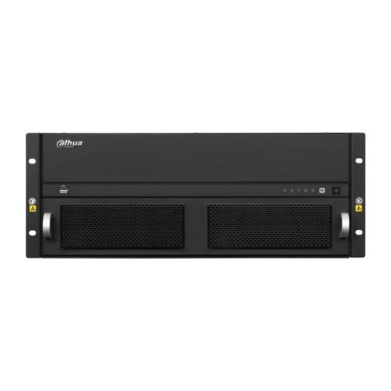
Figure 1- 2 Front panel, for displaying device working status; ON/OFF button. Device power indicator. Off: Not operating after plugged in. Red: Operating. Device alarm indicator. Red: Alarm on. Off: Alarm off. Device tatus indicator. Yellow: Device is properly running. ... -
Page 10: Control Panel
Figure 1- 3 Interface Function Reset Button 1, support restoring to default settings Mainboard 1, display mainboard power status Power Indicator System Status 1, display system working status Indicator PCI-E Status 1, display PCI-E working status Indicator USB Port 3, as 1 USB 3.0 and 2 USB 2.0 for connection to mouse, keyboard, USB 1, for local display output Audio Input... -
Page 11: Function Card
Function Card adopts blade module design, and is mainly used to input analog, digital video and centralize encoding compression, achieving remote preview, network centralized storage and etc. 1.5.1 VEC0404HD-M70 Video Matrix Platform 4-CH HD DVI Encoding Card Please see Figure 1- 5. -
Page 12: Vec0404Hv-M70Video Matrix Platform 4-Ch Vga Encoding Card
Support picture compression in 4 CIF under JPEG standard or CIF and net transmission Support watermark technology 1.5.1.2 Interface introduction VIN video input interface, DVI-I interface 1.5.1.3 Technical Specifications Model VEC0404HD-M70 A/V Input Video Input 4-ch, DVI-I Video H.264 Encoding Compression Parameter... -
Page 13: Vec0804Hs-M70 Video Matrix Platform 8-Ch Hd Sdi Encoding Card
4 indicators High speed connector, including x4 PCI-E gen2,12V DC power Encoding Function VGA HD input port: UXGA@60Hz 1080P@60Hz,1080P@50Hz,720P@50Hz,720P@60Hz,1024x768@60Hz,1024x768@75Hz ,1280x1024@60Hz,1280x1024@75Hz; Adopts H.264 video compression technology Video encoding parameter is adjustable in each channel, including resolution, bit stream rate, image quality and etc. -
Page 14: Vec0804Hc-M70 Video Matrix Platform 8-Ch Hdcvi Encoding Card
1.5.3.1 Main Features and Performance Features 8-ch HD-SDI video interface input 2-ch RS485 interface 2 buttons, hot swap 4 indicators High speed connector, including x8 PCI-E gen2, 12V DC power Encoding Function Adopts H.264 video compression technology ... - Page 15 1.5.4.1 Main Features and Performance Features 8-ch BNC video input interface, support HDCVI signal input. 8-ch audio input, support external and built-in. Countercharge 2 buttons, hot swap 4 indicators High speed connector, including x4 PCI-E gen2, 12V DC power Encoding Function ...
-
Page 16: Vdc0404D-M70 Video Matrix Platform 4-Ch Hd Dvi Decoding Card
1.5.5 VDC0404D-M70 Video Matrix Platform 4-CH HD DVI Decoding Card Please see Figure 1- 9. Figure 1- 9 1.5.5.1 Main Features and Performance Features 4-ch DVI digital video interface output 2 buttons, hot swap 4 indicators High speed connector, including x4 PCI-E gen2, 12V DC power Decoding Function ... -
Page 17: Vs0201R-M70 Video Matrix Platform M70 Series Raid Card
Please see Figure 1- 10. Figure 1- 10 1.5.6.1 Main Features and Performance Features 4-ch VGA digital video interface output 2 buttons, hot swap 4 indicators High speed connector, including x4 PCI-E gen2, 12V DC power, Decoding Function ... - Page 18 Figure 1- 11 1.5.7.1 Main Features and Performance Features 2 MINI SAS ports, may connect to external disk matrix 1 button, hot swap 8indicators (MINI SAS work indicator) High speed connector, including x4 PCI-E gen2, 12V DC power Storage Function ...
-
Page 19: Open-Package Inspection And Wiring
2 Open-Package Inspection and Wiring 2.1 Inspection Procedure When you receive video matrix platform, please check for obvious external damage. The material of product package should be able to protect the product from majority impacts during transportation. Secondly please open the package, and check all accessories see if any part is missing. You may refer to accompanied accessory bag. -
Page 20: Local Interface Config
3 Local Interface Config 3.1 Software Interface Basic Operation 3.1.1 Boot Up Device Plug in power line, and press power switch on front panel. Power indicator turns on and device boots up followed by boot interface which lasts for 90s. When you boot up device, please keep the following in mind: Make sure whether the supplied voltage is within 100~240V 47~63Hz. - Page 21 Figure 3- 1 The system login interface is shown as in Figure 3- 2. System consists of four accounts (defaulted): Username: admin. Password: admin. (administrator, local and network) Username: 888888. Password: 888888. (administrator, local only) Username: 666666. Passwords: 666666(Lower authority user who can only monitor, playback, backup and etc.) ...
-
Page 22: Main Interface Introduction
Figure 3- 2 3.1.4 Main Interface Introduction After you logged in, you will enter main interface as shown in Figure 3- 3 (for various icon definitions, please refer to the following Chart 3- 1). Figure 3- 3... -
Page 23: Output Device Tree Introduction
Name Function Description Current Display current output slot name Output Display current output screen or cubeless video wall’s splicing illustration. Display Click channel, and if its corresponding area turns yellow, it is selected window successfully. Support1, 4, 8, 9, 16 channel display at the same time. Display mode:single channel, 4-ch, 8-ch, 9-ch and 16-ch available. - Page 24 Figure 3- 4 Name Function Description List of output card inserted in slot, when an output card is inserted into Output Card current slot, will display. You may click it to extend the list as will List Area . Meanwhile the current output card’s corresponding output change to interface name will be listed.
-
Page 25: Input Device Tree Introduction
Chart 3- 2 3.1.6 Input Device Tree Introduction The input device tree is show as follows; please see Figure 3- 5 and Chart 3- 3. Figure 3- 5... -
Page 26: Display Control Area Introduction
Name Function Description List of Decoding Card inserted in slot, when an Decoding Card is inserted Decoding into current slot, will display. You may click it to extend the list as will Card List Area . Meanwhile the current Decoding Card’s corresponding input change to interface name will be listed. -
Page 27: Display Setting
Name Function Description When current output interface’s current output channel does not have Blank Area corresponding input channel, the status info is blank. You may click this channel to view it, and its corresponding area will turn yellow. If current output interface’s output channel has been set up remote input device device channel, then device ID, IP address, device type, channel Remote Input... - Page 28 Figure 3- 8 In display window, select corresponding channel and then its corresponding window turns yellow. Please see Figure 3- 8.
- Page 29 Figure 3- 9 Switch to input device list. Please see Figure 3- 9.
- Page 30 Figure 3- 10 Double click corresponding input channel and then you may config video to output interface. Please see Figure 3- 10. Double click homepage, you will see Figure 3- 11.
-
Page 31: Input Group
Figure 3- 11 E-zoom: When input device supports e-zoom, you can use this function. Close Video: Delete current output screen’s channel configuration. Cubeless: Cubeless video wall. Input Group: Config input group. You can display all video config of input group on the output screen. - Page 32 Figure 3- 12 Step 2. Click add. You will see Figure 3- 13. Figure 3- 13...
- Page 33 Step 3. Select input source. means selected. Click add, and fill in name of input group. Click OK. See Figure 3-15 and Figure 3-16. Figure 3- 14...
- Page 34 Figure 3- 15 Step 4. You may continue adding if you need. If you want to delete input group, you can check the small box in front of designated group and click delete. Click OK to confirm. When you are done, click OK to exit. You can open the input group you added in Figure 3-17.
- Page 35 Figure 3- 16 Step 5. In output device list, double click output channel name and select one output channel. You will see its corresponding window turns yellow. Please see Figure 3- 17.
- Page 36 Figure 3- 17 Step 6. Switch to input device list. Double click configured input group, you will see configured signal source appear on output channel. See Figure 3-19.
-
Page 37: Scheme
Figure 3- 18 Note: When signal of input is more than the max split of output screen, auto tour starts. 3.1.10 Scheme Step 1. Click scheme, and you will enter Figure 3- 19. - Page 38 Figure 3- 19 Step 2. Click add to add new scheme. See Figure 3- 20. Figure 3- 20 Step 3. If the name has already existed, you may rename it. See Figure 3- 21.
-
Page 39: Advanced Menu Operation
Figure 3- 21 Step 4. You may delete and load existing scheme. Note: If the scheme is not configured, you cannot save it. 3.2 Advanced Menu Operation 3.2.1 Menu Navigation Main Level Option Note Menu Submenu SATA interface status, HDD total capacity, free space, video HDD Info start/end time and etc. -
Page 40: Menu Operation
AV encoding mode, frame rate, quality and other parameter Encode setting It includes timing setting for general video record, motion detect Schedule and external alarm. RS232 To set serial function, baud rate and other parameters. To set network address, video data transmission protocol and Network other parameters and PPPoE, DDNS function. -
Page 41: Info
Figure 3- 22 3.2.3 Info After you enter information menu, the submenu is shown as below. Please see Figure 3- 23. There are total five icons: HDD info, bit per second (BPS), log, version, online user and status. Figure 3- 23 3.2.3.1 HDD Info... - Page 42 It displays HDD interface status, total capacity of all HDDs, free space, video record start and end time, status and etc. Please see Figure 3- 24. Figure 3- 24 In HDD info, add “*” after SN means is it current working disk (i.e. 1*). Status info shows whether there is conflict in the disk.
- Page 43 Figure 3- 25 Note: You may left click view recording times button to switch to view type and capacity. 3.2.3.2 Log The interface displays system log file. Log types include system, config, storage, alarm, record, account, clear, and playback. Pleased select start time and end time, then click search button. You can view the log files in list format.
- Page 44 Figure 3- 26 3.2.3.3 BPS This interface real time displays bit stream (Kb/S) and used space (MB/H), while wave pattern better shows changes in bit stream. Please see Figure 3- 27. Figure 3- 27...
-
Page 45: Online Users
3.2.3.4 Version The interface displays system version, WEB version and their SN. You may click start to upgrade system after connect a USB device to device. Note: The upgrading file in USB must be named update.bin. 3.2.3.5 Online Users In this interface, you can view and management online users connected to device. -
Page 46: System Setting
Figure 3- 29 Fan speed: It displays current speed of two fans. Card information: It displays card information of each slot, including type, encoding/decoding. It also displays current status of each card, including data exchange and online stat us. ... - Page 47 Figure 3- 30 Note: Only authorized user can enter system setting. 3.2.4.1 General General setting interface is shown as follow; please see Figure 3- 31. Figure 3- 31...
- Page 48 System time: You can set system date and time. After you modify setting, you must save your change to make changes effective. Date format: There are three types: YYYY-MM-DD: MM-DD-YYYY or DD-MM-YYYY. Date separator: There are three denotations to separate date: dot, beeline and solidus. ...
- Page 49 Figure 3- 33 Note: Since system time is very important, do not modify time casually unless there is a must! Before your time modification, please stop record operation first! 3.2.4.2 Encode Encode setting interface is shown as below. Please see Figure 3- 34. Figure 3- 34 ...
- Page 50 Video/audio: You can enable or disable the video/audio. Main bit stream video by default is ON. For extra bit stream, you must select video prior to selecting audio. Audio format: You can select audio format: G711a, G711u and PCM. Note: In encode setup, you cannot set encode parameter for remote device.
- Page 51 Figure 3- 36 Analog channel: Please select the channel number first. Slot: Please select the slotl number first. You can select “all” if you want to set for the whole slots. Video input: Please select the channel number first. You can select “all” if you want to set for the whole channels.
- Page 52 Figure 3- 37 Device: Remote device IP address. Channel: Remote device channel no. Quick Setting This function allows you to copy one channel setting to another. After setting in channel 1, you can click copy button and turn to channel 3 and then click paste button or vice versa. You can finish setting for one channel and then click save button or you can finish all setting and then click save button to memorize all the settings.
- Page 53 Figure 3- 38 Function: There are various devices for you to select. Console is for you to use the COM or mini-end software to upgrade or debug the program. The keyboard is for you to control the device via the special keyboard. Adapter is to connect to the PC to transfer data directly. Net keyboard is for you to use the special keyboard to control the device.
- Page 54 Figure 3- 39 Network Mode: It includes multi-addresses, fault tolerance, load balance, net bridge and link aggregation. Aggregation Set: Under net bridge mode under. Net bridge Set: Under net bridge mode only. This setup can bind any two network cards to one net bridge as one network card can only bind one net bridge.
- Page 55 view current IP information. You must set IP-related parameters again if you disabled DHCP. Besides, when PPPoE is operating, you cannot modify IP/Subnet mask /Gateway. TCP port: Default value is 37777. You may set this port. UDP port: Default value is 37778. You may set this port. ...
- Page 56 Figure 3- 41 3.2.4.5.2 NTP Setting Figure 3- 42 You need to install SNTP server (Such as Absolute Time Server) in your PC first. In Windows 7 OS, you can use command “net start w32time” to boot up NTP service. NTP setting interface is shown as in Figure 3- 42.
- Page 57 New Deli GMT+5 Bangkok GMT+7 Beijing (Hong Kong) GMT+8 Tokyo GMT+9 Sydney GMT+10 Hawaii GMT-10 Alaska GMT-9 Pacific Time(P.T) GMT-8 American Mountain Time(M.T) GMT-7 American Central Time(C.T) GMT-6 American Eastern Time(E.T) GMT-5 Atlantic Time GMT-4 Brazil GMT-3 Middle Atlantic Time GMT-2 ...
- Page 58 3.2.4.5.5 UPNP Figure 3- 44 The UPNP protocol is to establish a mapping relationship between the LAN and the WAN. Please see Figure 3- 44. UPNP on/off :Turn on or off the UPNP function of the device. Status: Display UPNP function status, including success, fail and searching. ...
- Page 59 Email setting interface is shown as in Figure 3- 46. Figure 3- 46 SMTP server: Please input your email SMTP server IP here. Port: Please input corresponding port value here. User name: Please input the user name to login the sender email box. ...
- Page 60 alarm occurs, the device will send data according to protocol format and client will receive designated data. Please see Figure 3- 47. Figure 3- 47 3.2.4.5.8 iSCSI Click system setting network network service setting iSCSI setting. Set its parameter, including host IP, port.
-
Page 61: Video Detection
Figure 3- 48 3.2.4.6 Video Detection Introduction: Please set in menu system settings detect. There are no settings of detection area, sensitivity or anti-dither in video loss and camera mask. You can drag your mouse to set motion detect area. You may right click to save your selection and exit setting. - Page 62 3.2.4.6.1 Motion detect When the system detects dynamic signal that reaches preset sensitivity via analyzing video image, motion detect alarm will turn on. The interface is shown below as in Figure 3- 49. Figure 3- 49 Note: Please make sure you have enabled motion detect function as the check box filled by ■.
- Page 63 Figure 3- 50 Sensitivity: System supports 1-6 levels. The sixth level has the highest sensitivity. Period: Click set button, you can see an interface is shown as in Figure 3- 50. You may set period of motion detect and during other periods, motion detect will remain off. Select designated days of week with six periods per day available for selection.
- Page 64 Figure 3- 52 Figure 3- 53 Anti-jitter: Here you can set anti-jitter time. If anti jitter is set to be 10s, then when motion detect is triggered, this signal will lasts 10s. Currently this function is on motion detect only. The value ranges from 5 to 600s.
- Page 65 Figure 3- 54 Buzzer: Buzzer rings when motion detection alarms. 3.2.4.6.2 Video Loss...
- Page 66 Figure 3- 55 In Figure 3- 55, select video loss from the type list. This function allows you to be informed when video loss occurred. You can enable alarm upload, send email and screen prompt function. Note: You can refer to setting in motion detect. 3.2.4.6.3 Camera Masking Figure 3- 56...
- Page 67 Camera masking interface is shown as in Figure 3- 56. When someone viciously masks the lens, or the output video is in one-color due to the environments light change, the system can alert you to guarantee video continuity. You may enable alarm upload, show message and send email function for alert.
- Page 68 Figure 3- 57 When card of corresponding slot is fiber encoding card and HDCVI encoding card, you can set countercharge front-end function. See Figure 3- 58. Figure 3- 58 After above setting is complete, as may countercharge front-end via video line, please refer to RS 485 control.
- Page 69 Display is shown below as in Figure 3- 59, Figure 3- 60 and Figure 3- 61. Figure 3- 59...
- Page 70 Figure 3- 60...
- Page 71 Figure 3- 61 Channel/output name: Click channel/output name to enter channel name interface where you may edit channel name. (support maximal 20 characters, which may vary among versions)
- Page 72 Figure 3- 62 Color setting: Click to enter image color output setting. Please see Figure 3- 62. Decoder screen setting: Click to enter setting of decoder screen. Please see Figure 3- 63. Figure 3- 63...
-
Page 73: Advanced
3.2.4.9 Default The default interface is shown in Figure 3- 64. Figure 3- 64 Click default icon, system pops up a dialogue box. Please see Figure 3- 64. Please highlight icon to select the corresponding function. After all the settings please click save button, system goes back to the previous menu. Note: System menu color, language, video standard, IP address, user account will not maintain previous setting after default operation! 3.2.5 Advanced... -
Page 74: Hdd Management
Figure 3- 65 3.2.5.1 HDD Management Here is for you to view and implement hard disk management. In menu, click advanced setting and then click HDD manage. Please see Figure 3- 66. You can see current HDD name, type, status, free capacity and total capacity. Operation include modify HDD property, change to read-write disk, read only disk, and clear disk. - Page 75 Figure 3- 66 Type: write-read disk and read-only disk. HDD: Set current port input remote storage directory or external HDD no. Channel HDD channel: You can set HDD channel according to your actual condition. Slot sets local video input. Digital channel sets remote video input. Please see Figure 3- 67.
- Page 76 Figure 3- 68 Abnormality interface is shown as in Figure 3- 68. In menu, click advanced setting and then click Abnormality. Event type: There are several options for you such as disk error, no disk, disconnection, IP conflict, MAC conflict and etc. You can set one and more events. ...
- Page 77 Figure 3- 69 3.2.5.4 Account Figure 3- 70 Here is for you to implement account management. Please see Figure 3- 70. For account management please note: For the user account name and the user group, the string max length is 6-byte. The backspace in front of or at the back of the string is invalid.
- Page 78 middle. The string includes the valid character, letter, number, underline, subtraction sign, and dot. System account adopts two-level management: group and user. No limit to group or user amount. For group or user management, there are two levels: admin and user. ...
- Page 79 Figure 3- 72 Add Group You can add group by inputting group name and then inputting some memo information if necessary. Enter add group interface and select rights over control panel, shut down, real-time monitor, playback, record, record file backup, PTZ, user account, system information view, alarm input/output setting, system setting, log view, clear log, upgrade system, control device and etc.
-
Page 80: Auto Maintain
3.2.5.5 Auto Maintain Figure 3- 74 Here you can set auto-reboot time and auto-delete old files setting. You can set to reboot device by specified time. You can set to delete files or expired files for the specified days. You can select proper setting from dropdown list. Please see Figure 3- 74. After all the settings please click save button, system goes back to the previous menu. - Page 81 Select config and click delete to delete config. Click add to add config of cubeless video wall. Please see Figure 3- 76. Figure 3- 76 Name: Name of the cubeless video wall. Row: Set number of rows of the cubeless video wall. ...
- Page 82 Figure 3- 78 Step 2. You can continue to add cubeless video wall or edit or delete added ones. Select cubeless video wall and click remove to delete it. Step 3. You can edit name of cubeless video wall as in Figure 3- 79. Figure 3- 79 Step 4.
- Page 83 Figure 3- 80 Click Add to add new Raid. Select corresponding level. Figure 3- 81...
-
Page 84: Remote Device
Click hot spare manager to set Raid hot spare disk which improves security. Figure 3- 82 3.2.6 Remote Device Note: This function must work with DVR or IPC. 3.2.6.1 IP Search In remote device interface, click IP search. You may search all remote devices in network. The display includes IP address, port, manufacturer protocol and type, please see Figure 3- Check box in front of remote device you want to add. - Page 85 Figure 3- 83 3.2.6.2 Manually Add In remote device, click manually add. A prompt pops up and you need to input device name, manufacturer, IP address, TCP port, username, password and channel number. Please see Figure 3- 84. Make sure you save changes. Add device into added device.
-
Page 86: Shutdown
Figure 3- 84 3.2.7 Shutdown Figure 3- 85 Double click shutdown button, system pops up a dialogue box for you to select. Please see Figure 3- 85. Logout menu user: log out menu. You need to input password when you login the next time. ... -
Page 87: Web Operation
4 Web Operation 4.1 Network Connection Before web client operation, please check the following items: Network connection is right for the device and PC. PC network setting is right, including IP address, subnet mask and gateway. (If there is no router in network, then allocate IP address in same net section. - Page 88 At login, system pops up warning information to ask you whether install webrec.cab control or not. Please click yes button. If you can’t download the ActiveX file, please make sure there is no plug-ins prohibiting this ActiveX file and meanwhile lower your IE security level. You will see the following interface after successful login in Figure 4- 2.
- Page 89 Audio: Whether turn on audio or not. (Note: Audio here is not related to audio in system setting.) Device IP, monitor From left to channel No. and right: zoom in, local network monitor record, snapshot, bit stream audio on, and close video.
- Page 90 Please see Figure 4- 6. From left to right are: image quality fluency full screen single window four windows six windows eight windows nine windows thirteen windows sixteen windows twenty windows ...
- Page 91 Hide PTZ Console Figure 4- 7...
- Page 92 Figure 4- 8 Please see Figure 4- 7 and Figure 4- 8. Auto scan: Select left border of camera auto scan via direction buttons, and click left border button to confirm. It is same for right border. Preset: Rotate the camera to designated position via direction buttons. Input preset value in corresponding box, and click add button to save.
- Page 93 Light Wiper: Remote control over light and wiper. On: Select speed dome image, click ON to overlay. Off: Turn off overlay. Up/down/left/right: Select menu item. 7 Image/Other Settings Image setting: select one channel with green box and you may set the brightness, contrastness, hue, and saturation.
- Page 94 Update Click update button, and select updating file. Please see Figure 4- 13, Figure 4- 14 and Figure 4- Figure 4- 13 Figure 4- 14 Figure 4- 15 Click BIOS to start updating.
-
Page 95: Matrix Control
Local Playback Web support playback of record file saved on PC. Click local playback, you will see a prompt box as in Figure 4-16. You need to select file to playback. Figure 4- 16 4.2.1 Matrix Control Via matrix, you can slit TV wall, and complete output and input config. Step 1. - Page 96 Figure 4- 18 Step 2. If you want to add new card or delete output screen and add again, please select to add and click Save. Step 3. Select slot to config. See Figure 4-19.
- Page 97 Figure 4- 19 The red area can be dragged to move. Step 4. Click Splice, and select area to splice, click OK. Step 5. Click Scheme. Step 6. Right click scheme to add. Later, you can right click a certain scheme to rename and delete, or double click scheme to operate.
-
Page 98: System Info
Step 11. You can refresh, add to favorites, sort favorites and add input group. Click add to favorites and sort favorites. Step 12. Enable tour. You can set tour interval time with 10-120s. 4.2.2 System Info 4.2.2.1 Version Info Here you can view hardware features, software version and its release date. Please see Figure 4- 20. - Page 99 Figure 4- 21 4.2.2.3 Here you can view system log. System logs are classified into: system operation, config, data management, alarm event, record, user, and deleted log. You can select classification to search by directly clicking on search button. The system will display logs in list format. You may click backup button to record log on PC. If you click delete button, the system will clear all log files.
- Page 100 Figure 4- 22 4.2.2.4 System Status Here you can view status of system CPU, memory, temperature, fan and power. Please see Figure 4- 23.
- Page 101 Figure 4- 23 4.2.2.5 Sub Card Status View sub card, fan and power status.
-
Page 102: System Config
Figure 4- 24 4.2.3 System Config 4.2.3.1 General... - Page 103 Figure 4- 25 Please see Figure 4- 25. System Time: Here is for you to modify system time. Please click Save button after your completed modification. Date Format: Y-M-D, M-D-Y or D-M-Y. Date Separator: ., - or /. ...
- Page 104 4.2.3.2 Encode Figure 4- 26 Please see Figure 4- 26. Slot: Here is for you to select corresponding slot. Channel: Here is for you to select a monitor channel. Signal type: Select signal type of current slot. ...
- Page 105 Figure 4- 27 Watermark: Here you can insert watermark into display. 4.2.3.3 Schedule Here you can select local or remote channels to record video for different periods and dates. Users may set multiple periods. Please see Figure 4- 28. Figure 4- 28 Steps: 1.
- Page 106 2. Set record period, and select designated day of week. (If you do not select, the setting is effective for the day only.) 3. After you finish settings, click OK to save. You will return to the above interface, and click OK to save.
- Page 107 Figure 4- 30 Please see Figure 4-37. Slot: Select slot to configure RS232. Channel: Select channel to configure RS232. Communication: Serial type as RS232, RS422 and RS485. RS422 and RS485 are for alarm card only. Function:Select corresponding COM protocol. ...
- Page 108 Figure 4- 31 Please see Figure 4- 31. Network mode: There are three modes of multiple, fault-tolerant and load balancing. Aggregation: Under net bridge mode only. Net Bridge: Under net bridge mode only. Bridge cycle set: Under net bridge mode only. ...
- Page 109 Max connection: system support maximal 128 users. 0 means there is no connection limit. DNS: It is 8 8 8 8 in general. Alternate DNS: It is 8 8 4 4 in general. Transfer QOS: You can prefer fluency, image quality or self-adaptive. Based on your selection, the stream will be automatically adjusted with QOS box checked.
- Page 110 Figure 4- 33 4.2.3.8...
- Page 111 Figure 4- 34 Please see Figure 4- 34. Here you can realize network time synchronization. Please enable current function and then input IP of the PC of SNTP server, port number, time zone and update interval. Please note the SNTP supports TCP transmission only and its port shall be 123.The update interval ranges from 0 to 65535.
-
Page 112: Alarm Center
Atlantic Time GMT-4 Brazil GMT-3 Middle Atlantic Time GMT-2 Update period can be set to 0 to 65535 min. Default is 10 min. Click save when you are done. When first two update get successfully, SNTP server will sync system time immediately. Note: Check to enable item after setup. - Page 113 Figure 4- 36 Please see Figure 4- 36. It allows you to establish the mapping relationship between the LAN and the public network. Same with local config. Here you can also add, modify or remove UPNP item. Port mapping: Enable UPNP function. Status: Display UPNP function status: successful, failed and searching.
- Page 114 Figure 4- 37 4.2.3.12 Timeset IP Filter After you enable Timeset IP filter, only when it filters devices on white list, it can modify time on the platform. See Figure 4- 38.
- Page 115 Figure 4- 38 4.2.3.13 ISCSI You may save local and remote video record inputted on device to remote storage server. You may also add multiple SVRs which allows you to save image or video from different channels to different servers. Please see Figure 4- 39.
- Page 116 Figure 4- 39 4.2.3.14 Multicast After multicast is enabled, login WEB, select multicast method. WEB will automatically get multicast address and add the group. Then you can monitor video via multicast. See Figure 4- 40.
- Page 117 Figure 4- 40 4.2.3.15 Detect By analyzing the video, system enable motion detection alarm when it detects the motion signal reached the specified sensitivity.
- Page 118 Figure 4- 41 Please see Figure 4- 41. Event type: There are three types: Motion detection/video loss/Camera Masking. Slot and Channel: Select channel name from the dropdown list. Enable: You need to check box to enable motion detection function. Region: You can set detect region. Video loss and video mask do not have this function. Sensitivity: There are 1-6 levels as 6 is highest sensitivity.
- Page 119 Figure 4- 42 Anti-dither: Anti-dither is duration of motion detect Its range is 5 to 600s. . Record channel: Select channel (multiple choices) and system automatically activates motion detection function to record once alarm occurs (working with motion detection function). You need to set period of motion detection in schedule setting and select auto in local record control.
- Page 120 Figure 4- 43 Slot and channel: Select channel for speed dome input. Port: Select port to control signal output. PTZ type: Select either local or other PTZ. Protocol: Select the corresponding dome protocol.(such as PELCOD) Address: Set corresponding dome address. Default value is 1. Please note your setting here shall comply with your dome address;...
- Page 121 Figure 4- 44 4.2.3.18 Input Title The interface may modify input channel name, name of remote device cannot be modifies by default. Control ID is no. of input channel. See Figure 4- 45.
- Page 122 Figure 4- 45...
- Page 123 Figure 4- 46 4.2.3.19 Picture Manager User can upload picture to the platform. Uploaded picture can be set as background of the platform. Picture size cannot exceed 8M with resolution of 4096*4096 and lower in JPG format. See Figure 4- 47.
-
Page 124: Display Setup
Figure 4- 47 4.2.3.20 Display Setup You can set corresponding slot-channel output, including resolution, display, HUE, brightness, contrast, saturation and margins. Display includes hot swap and force. See Figure 4- 48. - Page 125 Figure 4- 48 4.2.3.21 Input Channel Setup It adjusts DVI, VGA signal inputs. When input signal resolution is special resolution which causes input signal to be incomplete, you can adjust to make input signal complete. See Figure 4- 49.
- Page 126 Figure 4- 49 Color Setting: It adjusts brightness, contrast, saturation, HUE, gain and phase of output image. See Figure 4- 50. Figure 4- 50...
- Page 127 Cover-Area: Select monitor option, and click the setup button to enter corresponding channel image. User can select area to be covered via mouse. One channel supports a max of 4 covered blocks. Select one covered block, click delete or right click to delete it. Single click to delete all covered blocks.
- Page 128 Figure 4- 53 4.2.3.22 NET Sniffer When network error occurs, such as disconnection, video frame is not fluent and etc., you can sniff network data on device. It sniff via IP, port and protocol type. Sniffer data can be saved to video matrix platform locally or USB.
- Page 129 Figure 4- 54 4.2.3.23 Default/Backup There are general, schedule, network, detect, display, encode, RS232, alarm, PTZ, and channel name as setup and output. You can select them separately or all. (You cannot select alarm.) See Figure 4-49.
-
Page 130: Advanced
Figure 4- 55 There are encode, remote device, PTZ, matrix control, group info, network, detect, output title, scheme, display setup, input title and intelligent. You can select multiple items. Export config: Click export config and select backup path to export all config on web. ... - Page 131 Figure 4- 56 Group setting is as follows; please see Figure 4- 57 and Figure 4- 58.
-
Page 132: Raid Config
Figure 4- 57 Figure 4- 58 4.2.4.2 Raid Config Figure 4- 59 Click Add to add Raid, and select corresponding level. - Page 133 Figure 4- 60 Click hot spare management to set Raid hot spare disk which improves security. Figure 4- 61...
- Page 134 4.2.4.3 Abnormality Figure 4- 62 Please see Figure 4- 62. Event type: The abnormal events includes: no disk, disk error, capacity warning, net error, IP conflict and MAC conflict. You can set linkage among these events. Enable: Check enable box. Alarm out: You can set event alarm out channel to alarm.
- Page 135 Figure 4- 63 Auto: System enables auto record function as you set in record schedule setting. Manual: Enable corresponding channel to record no matter what period applied in the record setting. Stop: Stop current channel record no matter what period applied in the record setting. 4.2.4.5 Account...
- Page 136 Figure 4- 64 Please see Figure 4-59. 1) Group Add group 1. The initial interface is as in Figure 4- 64. Upper level is group which can be extended into user list by clicking on +. 2. Click add group button as in Figure 4- 65. Input group name and select authority group from list.
- Page 137 Figure 4- 65...
- Page 138 Figure 4- 66 2) User Operation Add user 1. Click add user button, and you will see interface as in Figure 4- 66. Input new username, password and its confirmation in the window, and then select authority for this user. 2.
- Page 139 3) Modify password Select one user, and click modify password button, then you will see the following interface as in Figure 4- 68. Input current password, new password and its confirmation. Click save when you are done. Figure 4- 68 4.2.4.6 User Control User control allows user to disconnect current online user or shield some user within a certain...
- Page 140 Figure 4- 69 4.2.4.7 Snapshot...
-
Page 141: Auto Maintenance
Figure 4- 70 Please see Figure 4-64. Slot: Select slot to snapshot. Snapshot mode: Select scheduled snapshot or trigger snapshot. You must check the box behind to enable scheduled snapshot. Frame rate: Set snapshot frame rate, support 1~7s/pic. Resolution: Channel support 1080P/720P/D1/HD1/BCIF/CIF/QCIF. Quality: There are six levels of quality: 10%, 30%, 50%, 60%, 80%, 100%. - Page 142 Figure 4- 71 4.2.4.9 Remote Device Here you can add remote device via automatic search or manually adding. Please see Figure 4- 72 and Figure 4- 73.
- Page 143 Figure 4- 72 Figure 4- 73...
- Page 144 By Group: Step 1. Click Group Manager to see Figure 4- 74. Figure 4- 74 Step 2. Select group, and click Add. See Figure 4- 75. Figure 4- 75 Step 3. Enter name, click OK. See Figure 4- 76.
- Page 145 Figure 4- 76 Step 4. Check input device on the left to add into group 1 and check group 1. See Figure 4- 77. Figure 4- 77 Step 5. Click Add to add input device into group 1. See Figure 4- 78.
- Page 146 Figure 4- 78 Step 6. Click Save to input grouping of input device. You can add sub group under current group level. 4.2.4.10 Ventilator Control You can set temperature to control speed of ventilator. See Figure 4-68.
- Page 147 Figure 4- 79 4.2.4.11 Directory Manager It is mainly for network keyboard to control matrix. See Figure 4-69.
- Page 148 Figure 4- 80 Step 1. Select root directory, as check the box in front of root directory. Click Add. See Figure 4- Figure 4- 81 Step 2. Input name, and fill in control no. Each group has different control no. If you enter same control no.
- Page 149 Figure 4- 82 Step 4. Click Add. See Figure 4- 83. Figure 4- 83...
-
Page 150: Search
4.3 Search Click search button, you can see an interface is shown as in Figure 4- 84 The record type includes the record, alarm, motion, local, and picture. Please select record playback mode, and then select start time, end time, slot and channel. Then please click search button, you can see the corresponding files in the list. - Page 151 Figure 4- 85 Tip: in parameter setting, you may select date from the dropdown list and click search date. Please see Figure 4- 86. Red circle is current system date, and grey number is start time of search. Figure 4- 86...
- Page 152 During playback, you may play, pause, stop, slowly play and quickly play via corresponding buttons on control bar. The channel No. and device IP of this record are displayed in playback window. Please see Figure 4- 87. IP and channel Figure 4- 87 Download: Select record, click download button, and the save dialogue pops up.
- Page 153 Figure 4- 88 You need to input record name, and click save button to start to download. The downloading progress bar will be displayed and the download button will change to a stop button. Please see Figure 4- 89 and Figure 4- 90. Figure 4- 89...
- Page 154 Figure 4- 90 Click open local record button, and select local record to play. Please see Figure 4- 91.
-
Page 155: Alarm
Figure 4- 91 4.4 Alarm Here you can set WEB monitoring alarm type and alarm sound only if you enable alarm upload function. Please see Figure 4- 92. In alarm type, select alarm event, check to enable event. When there are event checked, you can view alarm info below. -
Page 156: Log Out
Figure 4- 93 4.6 Log Out Click log out button, system goes back to log in interface. You need to input user name and password to login again. -
Page 157: Dss Operation
5 DSS Operation Besides web-based operation, you can log in device via Digital Surveillance System (DSS). For detailed instructions please refer to DSS user’s manual. -
Page 158: Faq
6 FAQ 6.1 FAQ Q: I cannot boot up the device properly after plug it to power supply. A: When you plug to power supply after you properly turned it off, you must press the start button on the front panel in order to properly boot up the device. Q: Device buzzer turns on when I press the start button. - Page 159 b) Video transmission is too long or degrading is too huge. c) Device color or brightness setting is not correct. Q:Decoding and wall mount process are not fluent. A:This may be due to: a) Poor network environment. b) Front-end device setup or malfunction. c) Limit in decoding channel capacity.
- Page 160 a) Period setting is not correct. b) Motion detection zone setting is not correct. c) Sensitivity is too low. 14. Q: I cannot login client-end or web. A: This may be due to: a) ActiveX control has been disabled. b) Network connection error. c) Network setting error.
-
Page 161: Maintenance
a) Camera quality is too low. Lens is dirty. Camera is installed against the light. Camera aperture setting is not correct. b) HDD capacity is not enough. c) HDD is damaged. 20. Q: I cannot playback the downloaded file. A: This may be due to: a) There is no video player. -
Page 162: Appendix A Mouse Control
Appendix A Mouse Control Note: This section is designed for mouse operation with right hand. User must connect a mouse to via USB interface in order to access the menu for mouse operation. Left click System pops up password input dialogue box if you have not logged in. mouse When you have selected one menu item, left click mouse to view menu content. - Page 163 Right click In real-time monitor mode, pops up shortcut menu: video off, cubeless screen, mouse input,scheme, main menu, logoff and power off. Among which, video off applies to turn off video of selected window. Cubeless screen applies to combine video of different screens into one screen. Input applies to group input channels.
-
Page 164: Appendix B Toxic Or Hazardous Materials Or Elements
Appendix B Toxic or Hazardous Materials or Elements Toxic or Hazardous Materials or Elements Component Name Cr VI PBDE Circuit Board ○ ○ ○ ○ ○ ○ Component ○ ○ ○ ○ ○ ○ Device Case ○ ○ ○ ○ ○... - Page 165 Dahua Technology CO.,LTD. Address:No.1199 Bin’an Road, Binjiang District, Hangzhou, PRC. Postcode: 310053 Tel: +86-571-87688883 Fax: +86-571-87688815 Email:overseas@dahuatech.com Website: www.dahuatech.com...
Need help?
Do you have a question about the VEC0404HD-M70 and is the answer not in the manual?
Questions and answers