Table of Contents
Advertisement
Quick Links
Advertisement
Table of Contents

Related Manuals for Hioki 3255-50 HiTESTER


Summary of Contents for Hioki 3255-50 HiTESTER
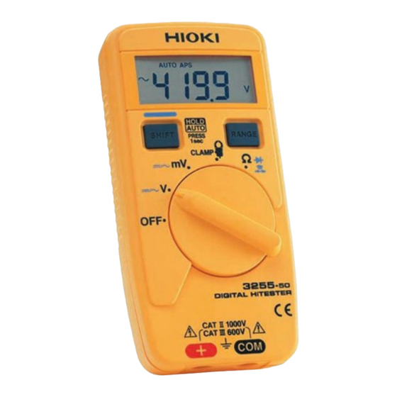
- Page 1 INSTRUCTION MANUAL 3255-50 DIGITAL HiTESTER...
-
Page 3: Table Of Contents
Contents Contents Introduction ............... 1 Inspection..............1 Safety Notes ............. 2 Usage Notes ............. 6 Chapter 1 Overview Product Overview ........13 Features ............ 13 Parts Names and Functions ...... 14 Chapter 2 Measurement Procedures Connection ..........17 Voltage Measurement ....... 19 Current Measurement ....... - Page 4 Contents Chapter 4 Specifications General Specifications ......33 Accuracy ........... 37 Chapter 5 Maintenace and Service Replacing the Batteries and Fuses ... 39 Cleaning and Storage ....... 42 Service ............43...
-
Page 5: Introduction
Introduction Introduction Thank you for purchasing the HIOKI "3255-50 DIGITAL HiTESTER." To obtain maximum perfor- mance from the product, please read this manual first, and keep it handy for future reference. Inspection When you receive the product, inspect it carefully to ensure that no damage occurred during ship- ping. -
Page 6: Safety Notes
Safety Notes Safety Notes This manual contains information and warnings essential for safe operation of the product and for maintaining it in safe operating condition. Before using the product, be sure to carefully read the fol- lowing safety notes. This product is designed to conform to IEC 61010 Safety Standards, and has been thor- oughly tested for safety prior to shipment. -
Page 7: Safety Symbols
Safety Notes Safety Symbols In the manual, the symbol indicates particu- larly important information that the user should read before using the product. symbol printed on the product indicates that the user should refer to a corresponding topic in the manual (marked with the symbol) before using the relevant function. - Page 8 Safety Notes Other Symbols Indicates the prohibited action Accuracy We define measurement tolerances in terms of f.s. (full scale), rdg. (reading) and dgt. (digit) values, with the following meanings: f.s. (maximum display value or scale length) The maximum displayable value or the full length of the scale.
- Page 9 Safety Notes Measurement categories (Overvoltage categories) This product conforms to the safety requirements for CAT III 600V, CAT II 1000V measurement products. To ensure safe operation of measurement products, IEC 61010 establishes safety standards for various electrical envi- ronments, categorized as CAT I to CAT IV, and called mea- surement categories.
-
Page 10: Usage Notes
• Before using the product the first time, verify that it operates normally to ensure that the no damage occurred during storage or shipping. If you find any damage, contact your dealer or Hioki representa- tive. • Before using the product, make sure that the insu- lation on the test leads is undamaged and that no bare conductors are improperly exposed. - Page 11 Usage Notes Observe the following to avoid damage to the product. • Installation and Operating Environment Between 0°C and 40°C; 80% RH or less; indoors only. However, it can be safely operated at as low as -10°C. • Do not store or use the product where it could be exposed to direct sunlight, high temperature or humidity, or condensation.
- Page 12 Usage Notes • Adjustments and repairs should be made only by technically qualified personnel. • If the protective functions of the product are damaged, either remove it from service or mark it clearly so that others do not use it inadvert- ently.
-
Page 13: Voltage Measurement
Usage Notes Connection and Measurement For other precautions and details, see explana- tions of the measurement procedures. Use only the specified test lead or clamp-on probe. Using a non-specified cable may result in incorrect measurements due to poor connection or other reasons. - Page 14 Usage Notes Resistance Measurement, Checking the Continuity or Diode Never apply voltage to test leads when the Resistance, Continuity or Diode Check func- tions are selected. Doing so may damage the product and result in personal injury. To avoid electrical accidents, remove power from the circuit before measuring.
- Page 15 Usage Notes • To prevent damage to the product and Clamp- on probe, never connect or disconnect a sensor while the power is on. • Be careful to avoid dropping the Clamp-on probe or otherwise subjecting them to mechani- cal shock, which could damage the mating sur- faces core adversely...
- Page 16 Usage Notes...
-
Page 17: Chapter 1 Overview
1.1 Product Overview Chapter 1 Overview 1.1 Product Overview This measurement product is a multi-functional digital multimeter capable of measuring DC and AC voltages, AC currents, and the resistance, and checking the diode and continuity. 1.2 Features Compliance with CE marking requirements The measurement product is designed to comply with the international safety standard (IEC61010) and EMC standards. -
Page 18: Parts Names And Functions
1.3 Parts Names and Functions 1.3 Parts Names and Functions LCD Display (page 15) SHIFT Button (page 15) RANGE Button (page 15) Function Selector Selects functions V, mV Voltage measurement CLAMP Current measurement Resistance measure- ment Continuity checking Diode checking Terminal Turns the power on/off COM Terminal... -
Page 19: Lcd Display
1.3 Parts Names and Functions LCD Display Indicates Auto Power Save is enable Indicates Autoranging Indicates diode check function function Indicates continuity check Indicates HOLD AUTO function function is enable. Indicates current mea- Blinks when on standby surement function for a trigger Clamp-on Indicates probe ranges... - Page 20 1.3 Parts Names and Functions...
-
Page 21: Chapter 2 Measurement Procedures
2.1 Connection Measurement Chapter 2 Procedures Observe the following precautions to avoid electric shock. • Always verify the appropriate setting of the function selector before connecting the test leads. • Disconnect the test leads from the mea- surement object before switching the func- tion selector. - Page 22 2.1 Connection Current measurement To perform measurement, an optional Clamp-on probe is required. Connect the red plug of the Clamp-on probe to terminal +, and the black plug to terminal COM. Connect the plug to the ter- minals securely. Black Clamp-on probe...
-
Page 23: Voltage Measurement
2.2 Voltage Measurement 2.2 Voltage Measurement • The maximum input voltage is 1000 VDC,1000 Vrms(sin), or 10 V•Hz. Attempt- ing to measure voltage in excess of the maximum input could destroy the product and result in personal injury or death. •... - Page 24 2.2 Voltage Measurement Move function mV measurement V measurement selector to the V or mV position ("V" or "mV" lights up, lights up). If you are not sure of the approximate volt- age level, select V first. When voltage measurement, press AC Voltage DC Voltage...
-
Page 25: Current Measurement
2.3 Current Measurement 2.3 Current Measurement To perform measurement, an optional Clamp-on probe is required. Connect the Clamp-on probes to the product first, and then to the active lines to be mea- sured. Observe the following to avoid electric shock and short circuits. •... - Page 26 2.3 Current Measurement • To prevent damage to the product and sensor, never connect or disconnect a probe while the power is on. • Check the position of the range switch of the Clamp-on probe before taking measurements. • Make sure the range setting of the product is the same as that of the Clamp-on probe before start- ing measurement.
- Page 27 2.3 Current Measurement Move the function selector to the CLAMP position. lights up) Set the measurement range Clamp-on probe When the measurement (option). range is set to 100A If you are not sure of the level 9010 of the current to be mea- sured, select a large range.
-
Page 28: Resistance Measurement
2.4 Resistance Measurement 2.4 Resistance Measurement • Never apply voltage to the test leads when Resistance function selected. Doing so may damage the product and result in personal injury. • To avoid electrical accidents, remove power from the circuit before measuring. Move the function selector to the Ω... -
Page 29: Continuity Check
2.5 Continuity Check 2.5 Continuity Check • Never apply voltage to the test leads when the Continuity check function is selected. Doing so may damage the product and result in personal injury. • To avoid electrical accidents, remove power from the circuit before measuring. Move the function selector to the Ω... -
Page 30: Diode Check
2.6 Diode Check 2.6 Diode Check • Never apply voltage to the test leads when the Diode Check function is selected. Doing so may damage the product and result in personal injury. • To avoid electrical accidents, remove power from the circuit before measuring. Move the function selector to the Ω... -
Page 31: Chapter 3 Additional Functions
3.1 Auto Range Function and Manual Range Additional Chapter 3 Functions 3.1 Auto Range Function and Manual Range Function Functions Auto range function: / CLAMP Manual range function: Auto range function _______________________ The Autoranging function automatically selects the optimum measurement range. Turning on the power also switches Autoranging on (AUTO lights up). - Page 32 3.1 Auto Range Function and Manual Range Manual range function ____________________ Press the RANGE button to active the manual range function (AUTO is turned off). Only Manual Range is available for current mea- surement (CLAMP). Range selection: V/ Ω Each pressing of the RANGE button selects the next larger range.
-
Page 33: Hold Auto Function
3.2 HOLD AUTO Function 3.2 HOLD AUTO Function Functions V/ mV/ Description Simply moving the test leads away from the mea- surement object holds the measured value. This function is useful when it is difficult to read the displayed value in the current location or both hands are being used to conduct the measure- ment. -
Page 34: Overflow Warning Function
3.3 Overflow Warning Function 3.3 Overflow Warning Function Functions V/ mV/ CLAMP When the measured value exceeds the maxi- Description mum indication (4199 counts), O.F is displayed and an intermittent sound is generated. O.F is displayed and an intermittent sound is generated also in the cases described below. -
Page 35: Auto Power Save Function
3.4 Auto Power Save Function 3.4 Auto Power Save Function Functions All functions Description Approximately 10 minutes after completing final operation, the measurement product automati- cally enters Power Save mode. When the mea- surement product is turned on, it automatically enters Auto Power Save mode (APS lights up). - Page 36 3.4 Auto Power Save Function...
-
Page 37: Chapter 4 Specifications
4.1 General Specifications Chapter 4 Specifications 4.1 General Specifications General Measurement Dual integration method AC measurement Average rectifying measurement system Function DC voltage ( V), AC voltage( AC current ( ) (using with the optional Ω clamp-on probe), Resistance ( Continuity check( ), Diode check( (judgment only) - Page 38 4.1 General Specifications General Range switching Auto/Manual Range Sampling rate 2.5 S/s +(V, Ω, continuity, diode) terminal Input terminals COM terminal OFF/ V/ mV/ CLAMP/ Ω Functions Buttons SHIFT, RANGE Power supply Two manganese (R03) batteries or two alkaline (LR03) batteries Battery-life indicates low battery warning...
-
Page 39: Electrical Characteristics
4.1 General Specifications Applicable Standards Safety EN61010-1:2001 EN61010-031:2002 Pollution Degree 2 Measurement Category CAT III 600 V, CAT II 1000 V (Anticipated Transient Over- voltage: 6000 V) EN61326:1997+A1:1998+A2:2001 +A3:2003 Dustproof and EN60529:1991 IP54 waterproof Electrical Characteristics Measurement See accuracy table (page 37) accuracy Accuracy guaran- 23°C±5°C (73°F±9°F), 80%RH or less... - Page 40 4.1 General Specifications Electrical Characteristics Rated power 3.0 VDC supply voltage 12 mVA (Max) (supply voltage 3.0 VDC) Maximum rated power Rated power 4 mVA (Typ) (supply voltage 3.0 VDC, in DCV mode) 0.1 mVA (Max) Power during auto (supply voltage 3.0 VDC, during Auto power saving Power Saving) Approx.
-
Page 41: Accuracy
4.2 Accuracy 4.2 Accuracy Accuracy Table (Accuracy guaranteed for one year at 23°C±5°C (73°F±9°F), 80%RH or less.) (rdg.: displayed value, dgt.: resolution) Voltage Measurement Range Accuracy Input Impedance ±(rdg.)±(dgt.) (Frequency range) 420.0 m ±1.0%±4 Approx.10 MΩ 4.200 ±1.0%±4 Approx.11 MΩ 42.00 ±0.5%±4 Approx.10 MΩ... - Page 42 4.2 Accuracy (rdg.: displayed value, dgt.: resolution) Current Measurement (3255-50 only. For accuracy of the combination of the Clamp-on probe and the 3255-50, add the measurement accuracy of the clamp-on probe) Range Accuracy Input Impedance ±(rdg.)±(dgt.) (Frequency range) 10.00 ±2.0%±4 20.00 ±2.0%±4 CLAMP...
-
Page 43: Chapter 5 Maintenace And Service
5.1 Replacing the Batteries and Fuses Maintenace and Chapter 5 Service 5.1 Replacing the Batteries and Fuses • To avoid electric shock when replacing the batteries and fuses, first disconnect the test leads from the object to be measured. • Before using the product after replacing the batteries or fuses, replace the cover and screw. -
Page 44: Replacing The Fuses
5.1 Replacing the Batteries and Fuses Replacing the Fuses Replace the fuse only with one of the speci- fied characteristics and voltage and current ratings. Using a non-specified fuse or short- ing the fuse holder may cause a life-threat- ening hazard. Fuse type: Model DMM-44/100, Fast-acting, Rating: 0.44 A/1000 V (AC/DC), Breaking capacity:... - Page 45 5.1 Replacing the Batteries and Fuses Necessary tool: Phillips screwdriver Disconnect the test leads from the measurement Rear case circuit, and make sure the function selector is in the OFF position. Turn the 3255-50 over and use a Phillips screw- driver to remove the one retaining screw.
-
Page 46: Cleaning And Storage
5.2 Cleaning and Storage 5.2 Cleaning and Storage Cleaning ________________________________ • To clean the product, wipe it gently with a soft cloth moistened with water or mild detergent. Never use solvents such as benzene, alcohol, acetone, ether, ketones, thinners or gasoline, as they can deform and discolor the case. -
Page 47: Service
• When sending the product for repair, remove the batteries and pack carefully to prevent damage in transit. Include cushioning material so the instrument cannot move within the package. Be sure to include details of the problem. Hioki can- not be responsible for damage that occurs during shipment. - Page 48 5.3 Service...
- Page 51 HIOKI 3255-50 DIGITAL HiTESTER Instruction Manual Publication date: September 2006 Revised edition 1 Edited and published by HIOKI E.E. CORPORATION Technical Support Section All inquiries to International Sales and Marketing De- partment 81 Koizumi, Ueda, Nagano, 386-1192, Japan TEL: +81-268-28-0562 / FAX: +81-268-28-0568 E-mail: os-com@hioki.co.jp...
- Page 52 HEAD OFFICE 81 Koizumi, Ueda, Nagano 386-1192, Japan TEL +81-268-28-0562 / FAX +81-268-28-0568 E-mail: os-com@hioki.co.jp URL http://www.hioki.co.jp/ HIOKI USA CORPORATION 6 Corporate Drive, Cranbury, NJ 08512, USA TEL +1-609-409-9109 / FAX +1-609-409-9108 3255D981-01 06-09H Printed on recycled paper...
Need help?
Do you have a question about the 3255-50 HiTESTER and is the answer not in the manual?
Questions and answers