Hioki DT4261 Instruction Manual
Hide thumbs
Also See for DT4261:
- Remote operation manual (11 pages) ,
- Manual (20 pages) ,
- Manual (36 pages)

Related Manuals for Hioki DT4261


Summary of Contents for Hioki DT4261
- Page 1 DT4261 Instruction Manual DIGITAL MULTIMETER Read carefully before use. Keep for future reference. Aug. 2021 Edition 1 DT4261A961-00 21-08H HIOKI DT4261A961-00...
- Page 2 HIOKI DT4261A961-00...
-
Page 3: Table Of Contents
Instrument Installation in the Measurement Location .........44 Using the instrument with the stand ......44 Using magnetic strap ..........45 Magnetic strap attachment procedure ...... 47 Strap attachment procedure ........49 Measurement Inspecting the Instrument Before Use ..51 HIOKI DT4261A961-00 DT4261A961-00... - Page 4 Filter Function (FILTER) ........79 Maximum, Minimum, Average, and Peak Values ...........82 Displaying MAX, MIN, AVG, PEAK MAX, and PEAK MIN in order ........... 82 Displaying “MAX and MIN” or “PEAK MAX and PEAK MIN” simultaneously ........83 Zero Adjustment ..........84 HIOKI DT4261A961-00...
- Page 5 When exposed to water during storage ....128 When condensation occurs ........129 Cleaning ..............130 Shipping Precautions ..........130 Disposal ..............130 Troubleshooting ..........131 Before returning for repair ........131 Error and Operation Display ......135 Fuse Replacement ........136 Fuse replacement procedure ........138 HIOKI DT4261A961-00...
- Page 6 Contents Appendix RMS and Average ........141 Index Warranty Certificate HIOKI DT4261A961-00...
-
Page 7: Introduction
® • The Bluetooth word mark and logos are registered trademarks owned by Bluetooth SIG, Inc. and any use of such marks by Hioki E.E. Corporation is under license. Other trademarks and trade names are those of their respective owners. -
Page 8: Checking Package Contents
Operating Precautions (0990A907) Options The options listed as follows are available for the instrument. To order an option, please contact your authorized Hioki distributor or reseller. Options are subject to change. Please check Hioki’s website for the latest information. HIOKI DT4261A961-00... - Page 9 *6: CAT III 600 V, 5 A *7: CAT III 1000 V, 2 A *8: CAT III 600 V, CAT II 600 V, 10 A *9: CAT III 600 V, 10 A *10: CAT IV 1000 V, 2 A HIOKI DT4261A961-00...
- Page 10 C0202 Carrying Case C0207 Carrying Case Magnetic strap (p. 4 5) Attach this strap to the instrument and secure it on the wall surface such as a metal plate for use. Z5004 Magnetic Strap Z5020 Magnetic Strap (Extra strength) HIOKI DT4261A961-00...
- Page 11 A communication adapter, USB cable, PC software, and communication specifications are included. The instrument data can be stored on the PC. Z3210 Wireless Adapter (p. 4 1, p. 9 2) With this adapter installed to the instrument, the wireless communications function can be used. HIOKI DT4261A961-00...
-
Page 12: Notations
Indicates the presence of a hazard caused by a strong magnet. The effects of the magnetic force can cause abnormal operation of heart pacemakers and/or medical electronics. Indicates an action that must not be performed. Indicates an action that must be performed. HIOKI DT4261A961-00... - Page 13 Indicates a grounding terminal. Indicates DC (Direct Current). Indicates AC (Alternating Current). Symbols for various standards Indicates the Waste Electrical and Electronic Equipment Directive (WEEE Directive) in EU member states. Indicates that the product complies with standards imposed by EU directives. HIOKI DT4261A961-00...
- Page 14 1 2 3 4 5 6 7 8 9 0 A different display is used in the case below (when fuse is blown). Accuracy Hioki expresses accuracy as error limit values specified in terms of percentages of reading and digits. Indicates the value displayed by the instrument. Limit...
-
Page 15: Safety Information
Carefully read the following safety notes before using the instrument. DANGER Familiarize yourself with the instructions „ and precautions in this manual before use. Failure to do so could cause improper use of the instrument, resulting in serious bodily injury or damage to the instrument. HIOKI DT4261A961-00... - Page 16 Protective gear Use appropriate protective insulation. „ Performing measurement using this instrument involves live-line work. Failure to use protective gear could cause the operator to experience an electric shock. Using protective gear is prescribed under applicable laws and regulations. HIOKI DT4261A961-00...
- Page 17 Applicable to test and measuring circuits connected directly to utilization points (socket outlets and similar points) of the low- voltage mains installation. EXAMPLE: Measurements on household appliances, portable tools, and similar equipment, and on the consumer side only of socket-outlets in the fixed installation. HIOKI DT4261A961-00...
- Page 18 EXAMPLE: Measurements on devices installed before the main fuse or circuit breaker in the building installation. Service Entrance Distribution Panel Internal Wiring Service Drop CAT II CAT III CAT IV Outlet Power Meter Fixed Installation See: “2.3 Use of Test Leads” (p. 35) HIOKI DT4261A961-00...
-
Page 19: Precautions For Use
Before use, verify that test lead insulation „ is not torn and that no metal is exposed. Using test leads or an instrument that is damaged could result in serious bodily injury. If you discover any damage, replace with replace with a Hioki-specified part. HIOKI DT4261A961-00... - Page 20 • In locations where it would be exposed to high humidity or condensation • In locations with an excessive amount of dust or metal particles Doing so could damage the instrument or cause it to malfunction, resulting in bodily injury. HIOKI DT4261A961-00...
- Page 21 Do not drop the instrument. „ Doing so could damage the product. Turn the rotary switch to OFF after use. A small amount of battery power is used in sleep mode in the auto power save function. HIOKI DT4261A961-00...
- Page 22 Doing so could cause serious bodily injury. Do not input voltage to the resistance „ measurement input terminal or the resistance measurement, continuity check, diode test, or capacitor function. Doing so could damage the instrument, resulting in bodily injury. HIOKI DT4261A961-00...
- Page 23 Doing so could cause electric shock. When using the instrument, use only „ Hioki-specified test leads or options. Using test leads and options other than those specified could cause bodily injury or a short circuit accidents. HIOKI DT4261A961-00...
- Page 24 If the instrument is not to be used for an extended period of time NOTICE Remove the battery if the instrument will not be „ used for an extended period of time. Failure to do so may cause the battery to leak, damaging the instrument. HIOKI DT4261A961-00...
-
Page 25: Overview
The Z3210 Wireless Adapter (option) is required. (p. 92 ) Supplied test lead The measurement category can be switched by sliding the protective finger guard. (p. 36 ) HIOKI DT4261A961-00... -
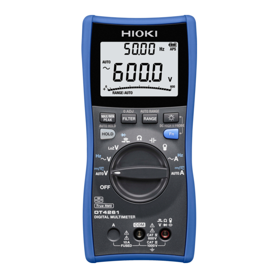
Page 26: Part Names And Functions
Part Names and Functions 1.2 Part Names and Functions Front Display (p. 2 7) Operation keys (p. 2 0) Rotary switch (p. 2 3) Measurement terminals (p. 2 4) Operation keys HIOKI DT4261A961-00... - Page 27 Z3210 is display backlight. installed) Specifies/cancels Specifies/cancels Disables the auto AUTO HOLD the hold function. the auto holding power save function function. (APS). Switches the – Enables/disables measurement the user settings items. retention function. HIOKI DT4261A961-00...
- Page 28 – – ON/OFF of the HID function. (Only when the Z3210 is installed) – Specifies/cancels – DC HIGH V PROBE mode* DC HIGH V PROBE * Used when the DC high voltage probe (on sale soon) is connected. HIOKI DT4261A961-00...
- Page 29 Ω (Input impedance 1.0 M ±20%) Continuity check, diode test Resistance measurement Electrostatic capacity measurement AC current measurement (with clamp sensor) AC current (A) measurement, frequency measurement AC/DC current measurement (automatic judgment), DC current measurement, AC+DC current measurement HIOKI DT4261A961-00...
- Page 30 Setting the rotary switch to any of the above measurements closes the current measurement terminal. Be sure to carefully read the following precautions for the terminals with the marking. • “Precautions during measurement” (p. 1 6) • “6.4 Fuse Replacement” (p. 136) HIOKI DT4261A961-00...
- Page 31 (p. 3 4, p. 4 3, and p. 1 39) Do not remove this label as the When the gasket (waterproof number is important. seal) attached to the battery cover shows signs of deterioration it needs to be replaced. Contact your authorized Hioki distributor or reseller. HIOKI DT4261A961-00...
- Page 32 Part Names and Functions Bottom Strap holes (p. 4 9) Drain holes (p. 1 28) HIOKI DT4261A961-00...
- Page 33 (on sale soon) is (p. 9 4) connected. AC, DC For details about the error, see The measured value in the “6.3 Error and Operation Display” main display exceeds the (p. 135). maximum value of the range. HIOKI DT4261A961-00...
-
Page 34: Alarm Display And Battery Indicator
The charge is only a reference for the continuous operation time. Power shutdown When the battery charge is 0% (less than 3.0 V ±0.1 V), [bAtt] in the display blinks for 3 seconds and the power is shut down. HIOKI DT4261A961-00... -
Page 35: Preparing For Measurements
As necessary, perform zero adjustment (p. 8 4). Connect the test leads to the object to be measured. (As necessary) Retain the measured value (p. 7 5). Black Move the test leads away from the object under measurement and then turn off the power. HIOKI DT4261A961-00... -
Page 36: Inserting/Replacing Batteries
Do not short-circuit the battery. „ Do not charge the battery. „ Do not disassemble the battery. „ Do not throw the battery into a fire. „ Doing so can cause the battery to explode, resulting in bodily injury. HIOKI DT4261A961-00... - Page 37 ” indicator lights up when battery voltage becomes low. Replace the batteries as soon as possible. • Before replacing the batteries, make sure that the rotary switch is OFF. • Handle and dispose of batteries in accordance with local regulations. HIOKI DT4261A961-00...
- Page 38 • The operating temperature range of the batteries provided with the instrument at the time of shipment is between −10°C and 45°C. When using the instrument outside of the specified temperature range, use batteries that are compatible with the operating temperature. HIOKI DT4261A961-00...
-
Page 39: Battery Installation/Replacement Procedure
Release the locks for the battery cover. Turn the locks 180° in the counterclockwise direction using the screwdriver or coin to align [UNLOCKED] with the symbol (2 places). Rear Lock LOCKED UNLOCKED UNLOCKED LOCKED Continued to the next page → HIOKI DT4261A961-00... - Page 40 If the cover is not attached properly, the waterproof and dust-proof performance cannot be maintained. Gasket (waterproof seal) After the battery cover is removed, the fuse can be seen. For details about how to replace the fuse, see p. 1 36. HIOKI DT4261A961-00...
-
Page 41: Use Of Test Leads
See: “Options” (p. 2 ) WARNING When using the instrument, use the test „ leads and options specified by Hioki. Using test leads and options other than those specified could cause bodily injury or short circuit accidents. When measuring the power line voltage, „... -
Page 42: L9300 Test Lead (Accessory)
Use the test leads with the correct „ measurement category displayed. Do not use the test leads if the metal pin „ is bent or the protective finger guard does not slide properly. Doing so could cause short circuit accidents. HIOKI DT4261A961-00... - Page 43 3.6 mm) When the white portion inside the cable is exposed, replace the test lead with a new L9300. Plug Connected to the measurement terminals on this instrument. (p. 24 ) Protective sleeves are provided. Remove them before use. HIOKI DT4261A961-00...
- Page 44 Rotate it until you hear a sound and make sure that the mark is pointing at [LOCKED]. Perform the above steps to change from measurement category II to measurement category III or IV as well. HIOKI DT4261A961-00...
-
Page 45: L9207-10 Test Lead (Option)
See: “Measurement categories” (p. 1 1) CAUTION When using the test leads with the sleeves „ attached, verify that the sleeves are free of damage. Performing measurement with a damaged sleeve attached could cause the user to experience electric shock. HIOKI DT4261A961-00... - Page 46 Grip the base of the sleeves and pull the sleeves off. Store removed sleeves for future use. Attaching the sleeves Insert the metal pins of the test leads into the holes of the sleeves, and firmly push them all the way in. HIOKI DT4261A961-00...
-
Page 47: Installing Wireless Adapter
Using the instrument with the cover removed could result in bodily injury. Besides, the cover cannot be secured unless it is locked. NOTICE Before handling the Z3210, touch metal (a door „ knob, etc.) to discharge static electricity. Static electricity may damage the Z3210. HIOKI DT4261A961-00... -
Page 48: Z3210 Wireless Adapter Installation Procedure
Set the rotary switch to OFF. Release the locks for the battery cover. Turn the locks 180° in the counterclockwise direction using the screwdriver or coin to align [UNLOCKED] with the symbol (2 places). Rear Lock LOCKED UNLOCKED UNLOCKED LOCKED HIOKI DT4261A961-00... - Page 49 Turn the locks 180° in the clockwise direction using the screwdriver or [LOCKED] coin and align with the symbol (2 places). If the cover is not attached properly, the waterproof and dust-proof performance cannot be maintained. Gasket (waterproof seal) Protective cap Z3210 HIOKI DT4261A961-00...
-
Page 50: Instrument Installation In The Measurement Location
Doing so could cause the instrument to fall or overturn, resulting in bodily injury or damage to the instrument. NOTICE Do not apply excessive force from „ above when utilizing the stand. Doing so may damage the stand. HIOKI DT4261A961-00... -
Page 51: Using Magnetic Strap
WARNING Keep the magnetic strap out of the reach „ of children. Magnets can be life-threatening if swallowed. If magnets are accidentally swallowed, immediately seek medical attention and follow the directions of the health authority. HIOKI DT4261A961-00... - Page 52 Keep the magnetic strap away from PCs, TV „ screens, electronic wrist watches, or other precision electronics devices. Failure to do so may damage the data and devices. HIOKI DT4261A961-00...
-
Page 53: Magnetic Strap Attachment Procedure
Release the locks for the battery cover. Turn the locks 180° in the counterclockwise direction using the screwdriver or coin to align [UNLOCKED] with the symbol (2 places). Rear Lock LOCKED UNLOCKED UNLOCKED LOCKED Continued to the next page → HIOKI DT4261A961-00... - Page 54 Turn the locks 180° in the clockwise direction using the screwdriver or coin and align [LOCKED] with the symbol (2 places). If the cover is not attached properly, the waterproof and dust-proof performance cannot be maintained. Place the magnet on the wall surface (metal plate), etc. Magnet HIOKI DT4261A961-00...
-
Page 55: Strap Attachment Procedure
Pass the strap through the strap holes at the bottom of the instrument as shown below. 45 mm or more Loop type Use a strap with a loop length of 45 mm or more. HIOKI DT4261A961-00... - Page 56 Instrument Installation in the Measurement Location HIOKI DT4261A961-00...
-
Page 57: Measurement
Using the damaged test leads or instrument can result in serious bodily injury. If any damage is found, replace the test leads with those specified by Hioki. IMPORTANT When the instrument is returned from a high temperature/... - Page 58 The coating of the test leads is If any damage is found, replace the neither broken nor frayed, or the test leads with those specified by Hioki. white portion or metal part within Otherwise, there is a risk of receiving the lead is not exposed.
- Page 59 If any of the display segments are All the display segments are lit missing, request repair. RANGE while the key is held down when the rotary switch is turned [AUTO V] with the power OFF. (p. 2 7) Displaying all LCD segments HIOKI DT4261A961-00...
- Page 60 • The grip makes a sound when it is locked. Abnormal: The lock is easily released. Corrective action: There is a risk of receiving an electric shock. Replace with those specified by Hioki. HIOKI DT4261A961-00...
- Page 61 Replace with those specified by Hioki. If the same condition persists even after the test leads are replaced, a malfunction of the instrument may have occurred. Stop the inspection Black and then request repair. Continued to the next page → HIOKI DT4261A961-00...
- Page 62 (In this example, the commercial supply, and then check the display. voltage level should appear.) Abnormal: The measured value does not appear. Corrective action: A malfunction may have occurred. Stop the inspection and then request repair. Black HIOKI DT4261A961-00...
- Page 63 Check the position of the rotary switch „ before measurement. Remove the test leads from the object „ under measurement before changing the position of the rotary switch. Failure to do so can cause serious bodily injury, short circuit, or damage to the instrument. HIOKI DT4261A961-00...
-
Page 64: Voltage Measurement
(p. 7 4). • Displayed values can frequently fluctuate due to induction potential even when no voltage is applied. This, however, is not a malfunction. • The 600 mV range is available only for DC voltage measurement. HIOKI DT4261A961-00... -
Page 65: Measuring Dc Voltage, Ac Voltage, And Dc/Ac Composite Voltage
Measuring DC voltage, AC voltage, and DC/AC composite voltage Measure the DC voltage, AC voltage, or DC/AC composite voltage. See: “4.8 DC Voltage Positive/Negative Judgment Function” (p. 88) Black Switches the measurement items. AC/DC automatic judgment DC voltage DC + AC voltage HIOKI DT4261A961-00... -
Page 66: Measuring Ac Voltage
Voltage Measurement Measuring AC voltage Measure the AC voltage. Measure the frequency simultaneously. The measured value is a true RMS. (p. 1 41) Black Switches the measurement items. AC voltage Frequency HIOKI DT4261A961-00... -
Page 67: Measuring Voltage With Low Input Impedance
Voltage Measurement Measuring voltage with low input impedance Ω Measure the voltage with 1 M input impedance to prevent false measurement due to stray voltage. Black HIOKI DT4261A961-00... -
Page 68: Frequency Measurement
This does not apply to cases where the value fluctuates due to noise. • During the measurement of low frequency voltage (current), if the auto range does not stabilize and the frequency cannot be measured, fix the voltage (current) range and measure again. HIOKI DT4261A961-00... -
Page 69: Continuity Check
Failure to do so could cause electric shock or damage to the instrument. Black Detection Threshold value Buzzer sound Red backlight Ω Ω Short circuit ±10 Sounds Turns on detection (continuous buzzer sound) Ω Ω Open detection ±10 Turns off HIOKI DT4261A961-00... -
Page 70: Diode Voltage Measurement
Failure to do so could damage the object to be measured. The open terminal voltage is approximately 2.0 V DC or less. In the case of the opposite Cathode Anode connection The measured value and [OVER] blink. Black HIOKI DT4261A961-00... -
Page 71: Resistance Measurement
NOTICE Check the specification of the object to be „ measured in advance. Failure to do so could damage the object to be measured. The open terminal voltage is approximately 2.0 V DC or less. Black HIOKI DT4261A961-00... -
Page 72: Electrostatic Capacity Measurement
Failure to do so could cause electric shock or damage the instrument. Do not measure the capacitor which has „ been charged. Doing so can cause the capacitor to explode, resulting in bodily injury or damage to the instrument. Also accurate measurement cannot be performed. HIOKI DT4261A961-00... - Page 73 Electrostatic Capacity Measurement Black When measuring the polar capacitor Connect the V terminal (red test lead) to the plus terminal of the capacitor and the COM terminal (black test lead) to the minus terminal. HIOKI DT4261A961-00...
-
Page 74: Current Measurement
The fuse may have blown. Check whether the fuse has blown. (p. 57 ) If so, replace it. (p. 1 36) When measuring an unknown current Set the range to auto (the default setting) or 10 A. HIOKI DT4261A961-00... -
Page 75: Measuring Ac Current
• Measurement is performed using DC coupling, and the AC component’s RMS value is calculated in software and displayed. • The bar graph displays RMS values for AC and DC components. Additionally, the GENNECT Cross waveform display shows waveforms for AC and DC components. HIOKI DT4261A961-00... -
Page 76: Measuring Dc Current/Ac Current
Current Measurement Measuring DC current/AC current Measure the DC current or AC current. Load Power supply Black Switches the measurement items. AC/DC automatic judgment DC current DC + AC current HIOKI DT4261A961-00... -
Page 77: Measurement With Clamp On Probe (Ac Current)
Current range Change the range in accordance with the actual measurement. If the range of the Clamp on Probe is changed during measurement, change the range of the instrument as well. Continued to the next page → HIOKI DT4261A961-00... - Page 78 Do not clamp the Do not pinch instrument around two the conductor. or more conductors. When the measured value and [OVER] blink The measured value has exceeded the maximum display counts. Increase the range by one step. HIOKI DT4261A961-00...
-
Page 79: Convenient Usage
An optimum measurement range is automatically selected. When the measurement function is switched using the rotary switch, the auto range is enabled. [RANGE: AUTO] lights up Pressing during auto-range operation will switch to manual- range operation with the range fixed at the current setting. HIOKI DT4261A961-00... -
Page 80: Measuring With The Manual Range
Example: When the range is 6.000 V to 1000 V 6.000 V 60.00 V 600.0 V AUTO 1000 V Switching from the manual range to the auto range Press for at least 1 second. HIOKI DT4261A961-00... -
Page 81: Hold Function (Hold)
Retaining the measured value manually (HOLD) Display update is stopped at a selected timing. (The bar graph is updated.) (Default setting: OFF) Press (Press it again to cancel the hold function.) lights up lights up Retention of the measured value. HIOKI DT4261A961-00... -
Page 82: Retaining The Measured Value Automatically (Auto Hold)
• If the input signal is too small for the relevant range, the measured value cannot be automatically retained. • The measured value will be automatically retained once it stabilizes within the stable range (which takes approx. 2 seconds). HIOKI DT4261A961-00... - Page 83 Example: 100.0 V Auto holding Example: 99.0 V Threshold for Measured value auto holding Dead zone Time Connect to the object Connect Connect to be measured Stable Disconnect Disconnect Disconnect range (1) Not retained automatically (the threshold is not exceeded). HIOKI DT4261A961-00...
- Page 84 120 counts AUTO A DC current 10 A Within 20 counts 20 counts AC + DC current *1: Auto holding is not available for measurement items not shown. *2: Auto holding is not available for the 600 mV range. HIOKI DT4261A961-00...
-
Page 85: Filter Function (Filter)
Additionally, it could cause attenuation of signals in the band being measured, preventing the instrument from displaying accurate measured values. HIOKI DT4261A961-00... - Page 86 Each time the key is pressed, the passband setting is changed. [100 Hz] [500 Hz] [oFF] When the desired passband setting is displayed for approximately 2 seconds, the setting is applied and then the measurement screen is displayed again. lights up blinks turns off HIOKI DT4261A961-00...
- Page 87 When measuring power supplies with a power frequency of 400 Hz, which is mainly used in ships and aircrafts Set the FILTER to [oFF] [500 Hz]. If the FILTER is set to [100 Hz], accurate measurement can not be performed. HIOKI DT4261A961-00...
-
Page 88: Maximum, Minimum, Average, And Peak Values
Each time the key is pressed, the main display is changed. The current measured value can be checked in the sub display. [MAX] [MIN] [AVG] [PEAK MIN] [PEAK MAX] When changing back to the normal display Press for at least 1 second. HIOKI DT4261A961-00... -
Page 89: Displaying "Max And Min" Or "Peak Max And Peak Min" Simultaneously
Each time is pressed, the “MAX and MIN” display and “PEAK MAX and PEAK MIN” display are switched. When changing back to the normal display Press for at least 1 second. HIOKI DT4261A961-00... -
Page 90: Zero Adjustment
*2: Count value for which zero adjustment can be performed in all ranges Zero adjustment is not applicable for maximum value of the peak value (PEAK MAX) or minimum value of the peak value (PEAK MIN). HIOKI DT4261A961-00... - Page 91 Screen displayed when zero adjustment fails Example: Resistance measurement Select the measurement function. Connect the test leads to the measurement terminals. Allow the test leads to short-circuit. Press for at least 1 second. Black Ω (After zero adjustment: 0.0 Measure the resistance. HIOKI DT4261A961-00...
-
Page 92: Backlight
The warning backlight operates only for the current measured value and not for the retained value or recorded value of the MAX, MIN, AVG, PEAK MAX, or PEAK MIN display function. See: “1.3 Alarm Display and Battery Indicator” (p. 28) HIOKI DT4261A961-00... -
Page 93: Auto Power Save (Aps)
Disabling the APS function With the power off, turn the rotary switch while holding down the HOLD key. [APS] goes off (Any position) Enabling the APS function again [APS] lights up Turn the power off and then back on again. HIOKI DT4261A961-00... -
Page 94: Dc Voltage Positive/Negative Judgment Function
Reference value: −10 V or less Measurement function: DC V, AUTO V, or LoZ V Enabling/disabling the DC voltage positive/negative judgment function With the power off, turn the rotary switch while holding down the MAX/MIN PEAK key. (Any position) HIOKI DT4261A961-00... -
Page 95: Communication With The Pc
Infrared asynchronous serial communication Communication method (half-duplex) • Response with measurement data Communication content • The key operation function can be set on the Transmission speed 9600 bps Data length 8 bits Stop bit Parity bit Delimiter CR+LF HIOKI DT4261A961-00... - Page 96 Communication with the PC Controls the instrument. Transmits data. Attaching the communication adapter to the instrument Attach the communication USB cable adapter to the instrument. Connect the USB cable to the communication Communication adapter. adapter Communication port HIOKI DT4261A961-00...
- Page 97 • It is possible to use the instrument while the communication adapter is attached, however, the communication adapter is excluded from the drop-proof. • When the wireless communications function is ON, communication using the DT4900-01 cannot be performed. HIOKI DT4261A961-00...
-
Page 98: Wireless Communications Function
When the instrument is placed on the floor or ground, the communication distance becomes shorter. It is recommended that you move the instrument from the floor or ground and place it on a desk or table or hold it by hand. HIOKI DT4261A961-00... - Page 99 1 second. function ON) Off: Wireless communications function OFF Blinking: Wireless communications in process Start GENNECT Cross and connect and register the instrument. Tap [Other]. [Instrument Select the instrument to Settings]. connect. Continued to the next page → HIOKI DT4261A961-00...
- Page 100 The instrument can record up to 99 events. The event recording will terminate when the recorded events reach 99 in number. When you start another event recording session, the instrument will delete previously recorded data. HIOKI DT4261A961-00...
-
Page 101: Excel ® Direct Input Function (Hid Function)
When you wish to use GENNECT Cross, disable the HID function. The setting whether the HID function has been enabled or disabled will not be saved in the instrument but in the Z3210. Measured values can be entered. Continued to the next page → HIOKI DT4261A961-00... - Page 102 The setting saved in the Z3210 is displayed. When [−−−−] is displayed Update the Z3210 to the latest version using GENNECT Cross (version 1.8 or later). See the procedure on the next page when changing the HID setting. HIOKI DT4261A961-00...
- Page 103 Turn on the power as follows. (Any position) After displaying the following screens in turn, the instrument will be turned off automatically. The power turns off automatically. Turn on the power again. The HID setting is changed. Continued to the next page → HIOKI DT4261A961-00...
- Page 104 2. Disable the Z3210’s HID function. (p. 9 7) 3. Use the Instrument Settings of GENNECT Cross to reconnect the instrument. For details, please visit the Z3210’s website. https://z3210.gennect.net HIOKI DT4261A961-00...
-
Page 105: Power-On Option Table
(Turn the rotary switch from OFF.) Setting Description Procedure/Display saved With power off (Any position) Disabling the auto power save function (APS) (See: p. 8 7) ([APS] off) With power off (Any position) Buzzer sound ON/ HIOKI DT4261A961-00... - Page 106 (Any position) positive/negative judgment function enabled/disabled (See: p. 8 8) With power off AUTO V (First position from OFF) Displaying all LCD If any of the display segments are missing, segments request repair. – (See: p. 5 3) HIOKI DT4261A961-00...
- Page 107 Power-On Option Table Setting Description Procedure/Display saved With power off (Second position from OFF) Software version Example: Ver 1.00 display – With power off LoZ V (Third position from OFF) Model number – display HIOKI DT4261A961-00...
- Page 108 The manufacturing month and year – shown in the following figure are August and 2021, respectively. With power off Ω HID setting check (Fifth position from OFF) (Only when Z3210 is installed) – (See: p. 9 6) HIOKI DT4261A961-00...
- Page 109 (See: p. 8 3) ON/OFF of the HID function With power off (Only when the –* Z3210 is installed) (Any position) (See: p. 9 7) *: The ON/OFF setting of HID is saved in the Z3210. HIOKI DT4261A961-00...
- Page 110 Power-On Option Table HIOKI DT4261A961-00...
-
Page 111: Specifications
40°C to 65°C (104.0°F to 149.0°F): Linearly reduces from 80% RH or less at 40°C (104.0°F) to 25% RH or less at 65°C (149.0°F) (non-condensation). Temperature derating Temperature (°C) Storage −30°C to 70°C (−22.0°F to 158.0°F), 80% RH or less temperature and (non-condensation) humidity range HIOKI DT4261A961-00... - Page 112 Rated supply voltage: 1.5 V DC × 3 Maximum rated power: 800 mVA Rated power: 50 mVA + 20% or less (Power voltage: 4.5 V, AUTO V, backlight off) 15 mVA + 20% or less (Power voltage 4.5 V, sleep mode) HIOKI DT4261A961-00...
- Page 113 For current terminal 11 A/1000 V Breaking capacity: 50 kA AC/30 kA DC, fast-blow type Diam. 10.3 × 38 mm Manufacturer: Hollyland The fuse can be changed by the user. Accessories See: p. 2 Options See: p. 2 HIOKI DT4261A961-00...
-
Page 114: Input And Measurement Specifications
DC V measurement: −60 dB or more (50 Hz/60 Hz) characteristics NMRR Noise rejection DC V measurement: −100 dB or more Ω characteristics (DC/50 Hz/60 Hz, 1 k CMRR unbalance) AC V measurement: −60 dB or more Ω (DC/50 Hz/60 Hz, 1 k unbalance) HIOKI DT4261A961-00... - Page 115 0.05 to 5 times/second (When measuring electrostatic capacitance, varies with the electrostatic capacitance value.) 1 to 2 times/second (frequency) • Bar graph: 25 times/second * The range movement time is not included. Peak value detection 1 ms or more time width HIOKI DT4261A961-00...
- Page 116 Accuracy Accuracy guarantee duration: 1 year guarantee Accuracy guarantee duration after adjustment made conditions by Hioki: 1 year Accuracy guarantee temperature and humidity range: 23°C ±5°C (73.0°F ± 9.0°F), 80% RH or less (Non- condensation) Accuracy guarantee supply voltage range: 3.0 V ±0.1 V or more (Until the power is off)
- Page 117 1000 V −1000 V to 1000 V ±1.0% rdg ±7 dgt Input impedance, overload protection, coupling type: The same as the DC voltage measured value Range movement: Based on the range movement of the DC voltage measured value HIOKI DT4261A961-00...
- Page 118 100 Hz: ±1.5% rdg added in the range of 40 Hz to 100 Hz, no specified accuracy over 100 Hz 500 Hz: ±0.5% rdg added in the range of 40 Hz to 500 Hz, no specified accuracy over 500 Hz HIOKI DT4261A961-00...
- Page 119 (±50 V to ±1000 V) Input impedance, overload protection, coupling type: The same as the AC + DC voltage RMS value (p. 112 ) Range movement: Based on the range movement of the AC + DC voltage RMS value HIOKI DT4261A961-00...
- Page 120 100 Hz: ±1.5% rdg added in the range of 40 Hz to 100 Hz, no specified accuracy over 100 Hz 500 Hz: ±0.5% rdg added in the range of 40 Hz to 500 Hz, no specified accuracy over 500 Hz HIOKI DT4261A961-00...
- Page 121 ±1.5% rdg ±7 dgt (±50 V to ±1000 V) Input impedance, overload protection, coupling type: The same as the AC voltage RMS value (p. 114 ) Range movement: Based on the range movement of the AC voltage RMS value HIOKI DT4261A961-00...
- Page 122 *1: The measurement range of 5.00 Hz and above is only for the 6.000 V range. The measurement range for other voltage ranges is 40.00 Hz to 99.99 Hz. *2: ±2 dgt should be added to 20% or less of the range. HIOKI DT4261A961-00...
- Page 123 Continuity ON threshold value: 25 ±10 (continuous buzzer sound, red backlight turns on) Ω Ω Continuity OFF threshold value: 245 ±10 Response time: Open circuit or short circuit is detected for at least 0.5 ms. Accuracy guarantee conditions: After zero adjustment HIOKI DT4261A961-00...
- Page 124 Current under overload Steady state: 15 mA or less Transient state: 1.6 A or less Accuracy guarantee conditions: After zero adjustment Auto range movement threshold value: More than 6000 counts for upper range Less than 540 counts for lower range HIOKI DT4261A961-00...
- Page 125 Steady state: 15 mA or less Transient state: 1.6 A or less Maximum count for each range: 1100 (1000 for 10.00 mF range) Auto range movement threshold value: More than 1100 counts for upper range Less than 100 counts for lower range HIOKI DT4261A961-00...
- Page 126 100 Hz: ±1.5% rdg added in the range of 40 Hz to 100 Hz, no specified accuracy over 100 Hz 500 Hz: ±0.5% rdg added in the range of 40 Hz to 500 Hz, no specified accuracy over 500 Hz HIOKI DT4261A961-00...
- Page 127 The same as the AC current (clamp sensor) RMS value (p. 120 ) The accuracy does not include the error of the Clamp on Probe. The maximum input is based on the Clamp on Probe specifications. *1: Minimum resolution 10 A HIOKI DT4261A961-00...
- Page 128 100 Hz: ±1.5% rdg added in the range of 40 Hz to 100 Hz, no specified accuracy over 100 Hz 500 Hz: ±0.5% rdg added in the range of 40 Hz to 500 Hz, no specified accuracy over 500 Hz HIOKI DT4261A961-00...
- Page 129 600.0 mA range. If the current frequency is displayed in the sub display, the current frequency range is fixed to the auto range mode. *1: ±2 dgt should be added to 20% or less of the range. HIOKI DT4261A961-00...
- Page 130 ±1.5% rdg ±7 dgt 35 m ±30% 10.00 A −10.00 A to 10.00 A ±1.5% rdg ±7 dgt Coupling type: The same as the DC current measured value Range movement: Based on the range movement of the DC current measured value HIOKI DT4261A961-00...
- Page 131 ±2.0% rdg ±7 dgt (±0.50 A to ±10.00 A) Input impedance, coupling type: The same as the AC + DC current RMS value Range movement: Based on the range movement of the AC + DC current RMS value HIOKI DT4261A961-00...
-
Page 132: Other Specifications
GENNECT Cross cannot be performed. Upgrade function Using GENNECT Cross, update the instrument firmware version. Compatible instrument firmware: Version 1.00 or later GENNECT Cross: Version 1.8 or later When the wireless communications function is ON, communication using the DT4900-01 cannot be performed. HIOKI DT4261A961-00... -
Page 133: Maintenance And Service
The calibration interval depends on factors such as operating conditions and environment. Please determine the appropriate calibration interval based on your operating conditions and environment and contact Hioki to calibrate it accordingly on a regular basis. HIOKI DT4261A961-00... -
Page 134: When Exposed To Water During Storage
10 times until no water drops are coming out. Turn the rotary switch to switch the shutter and drain water from all the 3 measurement terminals. HIOKI DT4261A961-00... -
Page 135: When Condensation Occurs
24 hours or longer. Otherwise, accurate measurement may not be performed. HIOKI DT4261A961-00... -
Page 136: Cleaning
Use the packaging in which the instrument „ was initially delivered and then pack that in an additional box. Failure to do so could cause damage during shipment. Disposal Dispose of the instrument in accordance with local regulations. HIOKI DT4261A961-00... -
Page 137: Troubleshooting
Include cushioning material so the instrument cannot move within the package. Be sure to include details of the problem. Hioki cannot be responsible for damage that occurs during shipment. Before returning for repair... - Page 138 2 3 in the display. position is not confirmed. Set the rotary switch to the proper position. The display Check the contents of the error display. If p. 1 35 indicates an the problem persists, request repair. error. HIOKI DT4261A961-00...
- Page 139 Solution Reference Would like to The fuse can be purchased via authorized p. 1 36 replace the fuse. Hioki distributor or reseller. Would like to know how to obtain the fuse. Would like to [FUSE OPEn] is displayed if the current p. ...
- Page 140 DT4900-01 Communication Package commands. (option) is required. For details on commands, see the Would like communication specifications in the CD to perform accompanied by the communication communication package. The specifications can also be using own downloaded from Hioki’s website. software. HIOKI DT4261A961-00...
-
Page 141: Error And Operation Display
Error and Operation Display 6.3 Error and Operation Display Display Description Solution Err 001 ROM error (program) Repair is necessary. Please contact your authorized Hioki Err 002 ROM error (adjustment data) distributor or reseller. Err 004 Memory error (hardware malfunction) Err 005... -
Page 142: Fuse Replacement
Fuse Replacement 6.4 Fuse Replacement If the fuse is blown, replace it with a new one. The fuses can be purchased via authorized Hioki distributor or reseller. See: “4 Check that the fuse is not blown.” (p. 5 7) See: “Fuse replacement procedure” (p. 138) - Page 143 It may cause a malfunction. Do not remove the fuse using the tip of the test „ lead. Doing so can bend the tip of the test lead. Continued to the next page → HIOKI DT4261A961-00...
-
Page 144: Fuse Replacement Procedure
Set the rotary switch to OFF. Release the locks for the battery cover. Turn the locks 180° in the counterclockwise direction using the screwdriver or coin to align [UNLOCKED] with the symbol (2 places). Rear Lock LOCKED UNLOCKED UNLOCKED LOCKED HIOKI DT4261A961-00... - Page 145 (2 places). If the cover is not attached properly, the waterproof and dust-proof performance cannot be maintained. Gasket (waterproof seal) Fuse Location at which to insert flathead screwdriver or other suitable tool HIOKI DT4261A961-00...
- Page 146 Fuse Replacement HIOKI DT4261A961-00...
- Page 147 100 V 111 V V (t) V (t) V avg V rms V m = V avg = V rms Sine wave Square wave V m: Maximum value, V avg: Average value, V rms: RMS, T: Time period HIOKI DT4261A961-00...
- Page 148 RMS and Average HIOKI DT4261A961-00...
- Page 149 Inspection before use ... 51 Connection cable set ....3 Installation ......14 Continuity......63 Current........68 L9207-10 ......39 L9300........36 Diode ........64 LoZ V ........61 Display ........27 Display all LCD segments ..53 Magnetic strap ...... 45 HIOKI DT4261A961-00...
- Page 150 Power-On Option ....99 Zero adjustment....84 Range ........73 Red backlight ......28 Resistance ......65 Rotary switch ......23 Serial number display ..102 Sleeve........40 Software version ....101 Specifications ..... 105 Stand ........44 Strap ........45 HIOKI DT4261A961-00...
- Page 151 HIOKI DT4261A961-00...
- Page 152 HIOKI DT4261A961-00...
- Page 153 HIOKI DT4261A961-00...
- Page 154 HIOKI DT4261A961-00...
Need help?
Do you have a question about the DT4261 and is the answer not in the manual?
Questions and answers