Table of Contents
Advertisement
Quick Links
Advertisement
Table of Contents

Related Manuals for Hioki 3801-50


Summary of Contents for Hioki 3801-50
- Page 1 3801-50 DIGITAL HiTESTER Instruction Manual...
-
Page 3: Table Of Contents
Contents Contents Introduction .................1 Verifying Package Contents ..........1 Safety Information ..............2 Operating Precautions ............5 1 Overview Product Overview .............7 Features ..............8 Names and Functions of Parts .........9 2 Measurement Pre-Operation Inspection ........17 Voltage Measurement ..........19 Current Measurement ..........21 Resistance Measurement ........23 Ω... - Page 4 Contents Recording Function ..........43 Relative (REL) Display Function ......45 Battery Indicator Function ........46 Communications Function ........47 Warning Functions ..........49 3.8.1 Terminal A Misconnection Warning ......49 3.8.2 Overload Warning ............50 4 Power On Options Communications Settings ........53 4.1.1 Communications Speed Setting (Baud Rate) ..53 4.1.2...
-
Page 5: Introduction
Introduction Thank you for purchasing the HIOKI “Model 3801-50 DIGITAL HiTESTER.” To obtain maximum performance from the instrument, please read this manual first, and keep it handy for future reference. Verifying Package Contents • When you receive the instrument, inspect it carefully to ensure that no damage occurred during shipping. -
Page 6: Safety Information
Safety Information This instrument is designed to comply with IEC 61010 Safety Standards, and has been thoroughly tested for safety prior to shipment. However, mis- handling during use could result in injury or death, as well as damage to the instrument. Be certain that you understand the instructions and precautions in the manual before use. - Page 7 The following symbols in this manual indicate the relative importance of cautions and warnings. Indicates that incorrect operation presents an extreme hazard that could result in seri- ous injury or death to the user. Indicates that incorrect operation presents a significant hazard that could result in serious injury or death to the user.
- Page 8 Measurement categories (Overvoltage categories) This instrument complies with CAT III (1000 V) and CAT IV (600 V) safety requirements. To ensure safe operation of measurement instruments IEC 61010 establishes safety standards for various elec- trical environments, categorized as CAT I to CAT IV, and called measurement categories.
-
Page 9: Operating Precautions
Using the instrument in such conditions could cause an electric shock, so contact your dealer or Hioki rep- resentative for replacements. (Model 3851-10 TEST LEAD) - Page 10 Measurement Precautions Observe the following precautions to avoid electric shock. • Always verify the appropriate setting of the func- tion selector before connecting the test leads. • Disconnect the test leads from the measurement object and terminals before switching the function selector.
-
Page 11: Overview 7
1.1 Product Overview Overview 1.1 Product Overview The 3801-50 is a multifunction, high-performance digital multimeter that can be used for voltage (DC/AC/AC+DC), current (DC/AC/AC+DC), resistance, continuity, diodes, electrostatic capacity, frequency, frequency counter, duty ratio, pulse width, and temperature measurement. addition, this instrument is equipped with a pulse output function that can be used to check a variety of pulse sig- nal instruments. -
Page 12: Features
1.2 Features 1.2 Features High-performance Handheld DMM The 3801-50 can display a maximum count of 51,000. It can even measure distorted waveforms with high-preci- sion using true RMS measurement. The basic accuracy for DC voltage measurement is 0.025% rdg. 5 dgt. -
Page 13: Names And Functions Of Parts
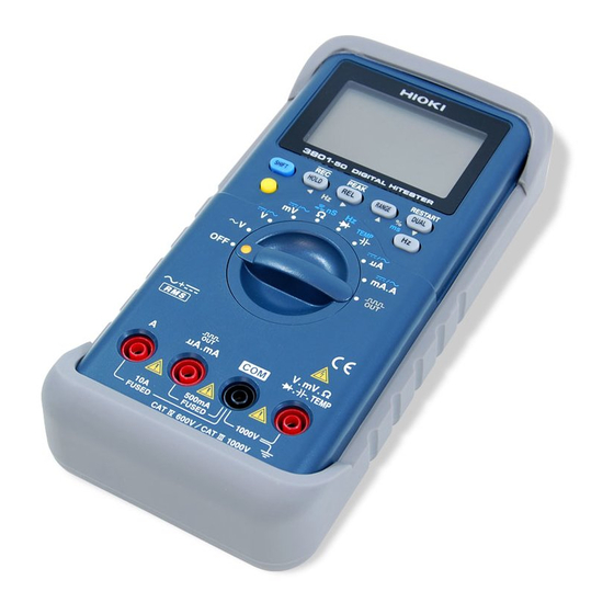
1.3 Names and Functions of Parts 1.3 Names and Functions of Parts The name and function of each part of the 3801-50 is described below. Front Panel Display (10 page) Operation Keys (11 page) Function Selector (12 page) Terminals (13 page) - Page 14 1.3 Names and Functions of Parts Display Sub display and units Main display and units Bar graph Lights when under remote control. Remote Lights when the pulse output function is being used. Lights when the DCV measurement or DCA measurement func- tion is being used.
- Page 15 1.3 Names and Functions of Parts Operation Keys SHIFT key SHIFT Locks the current measured value. (Hold function) HOLD Holding this key down toggles the recording function ON/OFF. Displays the relative value. (Relative value display function) Holding this key down toggles the peak hold function ON/OFF.
- Page 16 1.3 Names and Functions of Parts Function Selector Pressing this key turns the instrument off. AC voltage measurement function Voltage measurement function Use the key to select DC, AC, or AC+DC. SHIFT Voltage measurement function up to 1000 mV. Use the key to select DC, AC, or AC+DC.
-
Page 17: Rear Panel
1.3 Names and Functions of Parts Terminals Terminal used for current measurement. (A function) A Terminal Connect the read test lead. Terminal used for current measurement and for pulse output. (μA, mA, pulse output function) μ A.mA Terminal Connect the read test lead. Common terminal used for all measurements. - Page 18 Holder Stand Pass the strap provided through the hole in the holster to Strap secure the 3801-50 for portable use. The strap can be Attachment used to suspend the instrument from a belt or hook when Hole there is no place to set it down.
-
Page 19: Measurement 15
Measurement Observe the following precautions to avoid electric shock. • Always verify the appropriate setting of the func- tion selector before connecting the test leads. • Disconnect the test leads from the measurement object before switching the function selector. • The maximum input voltage is 1000 VDC, 1000 Vrms (sin) or 10 VHz. - Page 20 The terminals do not have sufficient spatial isola- tion. To avoid electrocution, do not touch the termi- nals. For safety reasons, when taking measurements, only use the test lead provided with the instrument. In order to protect the tips of the test leads, the test leads are capped when the unit is shipped from the factory.
-
Page 21: Pre-Operation Inspection
Before using the instrument the first time, verify that it operates normally to ensure that the no damage occurred during storage or shipping. If you find any damage, con- tact your dealer or Hioki representative. Inspection • Is the battery indicator ( ) lit? →If it is lit, replace the battery. - Page 22 2.1 Pre-Operation Inspection Connect the red test lead to the V terminal, and the black test lead to the COM terminal. Black Short the tips of the red and black test leads by touching them together. • Buzzer sounds. • Value stabilizes around 0 Ω. →...
-
Page 23: Voltage Measurement
2.2 Voltage Measurement 2.2 Voltage Measurement • Note that the instrument may be damaged if voltage or current the measurement range. • When the power is turned off, do not apply voltage or current to the measurement terminal. Doing so may damage the instrument. - Page 24 2.2 Voltage Measurement <Example> Connect the test leads to the object ACV Measurement being tested. Black DCV Measurement Black Read the value displayed in the main display. <Example> When measuring AC voltage To display the frequency, press the or the key.
-
Page 25: Current Measurement
2.3 Current Measurement 2.3 Current Measurement Never apply voltage to the test leads. Doing so may damage the instrument and result in personal injury. To avoid electrical accidents, remove power from the circuit before measuring. When a test lead is connected to terminal A, an alarm sounds if the function switch is set to a func- tion other than mA or A. - Page 26 2.3 Current Measurement Set the function switch. mA.A mA.A: For measuring voltages above 5100 μA μA: For measuring voltages below 5100 μA μA If you are not sure of the voltage to be mea- sured, set the function switch to "mA.A". Use the key to select either SHIFT...
-
Page 27: Resistance Measurement
2.4 Resistance Measurement 2.4 Resistance Measurement Never apply voltage to the test leads. Doing so may damage the instrument and result in personal injury. To avoid electrical accidents, remove power from the circuit before measuring. 2.4.1 Resistance Measurement ( Ω Ω... -
Page 28: Conductance
2.4 Resistance Measurement 2.4.2 Conductance (1/ Ω )Measurement (nS) The conductance measurement displays the reciprocal of the resistance. The display unit is "nS" (nanosiemens). For example, if the resistance is 40 MΩ, the conductance measurement will be 1/40 MΩ = 25 nS. (M is 10 , n is 10 If the resistance is infinity, 0 nS is displayed. -
Page 29: Continuity Check
2.5 Continuity Check 2.5 Continuity Check Never apply voltage to the test leads. Doing so may damage the instrument and result in personal injury. To avoid electrical accidents, remove power from the circuit before measuring. Set the function switch. Select with the key. -
Page 30: Diode Check
2.6 Diode Check 2.6 Diode Check Never apply voltage to the test leads. Doing so may damage the instrument and result in personal injury. To avoid electrical accidents, remove power from the circuit before measuring. Set the function switch. Connect the test leads to the test ter- minals. -
Page 31: Capacitance Measurement
2.7 Capacitance Measurement 2.7 Capacitance Measurement Never apply voltage to the test leads. Doing so may damage the instrument and result in personal injury. To avoid electrical accidents, remove power from the circuit before measuring. Set the function switch. If you want to change the range, press the key. -
Page 32: Frequency Measurement
2.8 Frequency Measurement 2.8 Frequency Measurement • Note that the instrument may be damaged if voltage or current the measurement range. • When the power is turned off, do not apply voltage or current to the measurement terminal. Doing so may damage the instrument. -
Page 33: Frequency Counter Measurement
2.8 Frequency Measurement 2.8.2 Frequency Counter Measurement Use for measurement of high frequencies, such as a CPU clock signal. Set the function switch. Select Hz counter with the key. SHIFT lights) SHIFT Select the division with the key. DUAL (Pressing the key toggles between 1 DUAL and 100.) -
Page 34: Duty Ratio Measurement
2.9 DUTY Ratio Measurement 2.9 DUTY Ratio Measurement The duty ratio is the ratio between the pulse width and the pulse cycle. This instrument displays this ratio in terms of 100 (%). Plus slope pulse width Minus slope pulse width Pulse cycle (=tw + tw Plus slope... -
Page 35: Pulse Width Measurement
2.10 Pulse Width Measurement 2.10 Pulse Width Measurement Set the function switch. See Section 2.2 Voltage Measurement (page 19) See Section 2.3 Current Measurement (page 21) See Section 2.8.2 Frequency Counter Mea- surement (page 29) SHIFT Use the key to select either SHIFT AC+DC DC, AC, or AC+DC. -
Page 36: Temperature Measurement
2.11 Temperature Measurement 2.11 Temperature Measurement Never apply voltage to the test leads. Doing so may damage the instrument and result in personal injury. To avoid electrical accidents, remove power from the circuit before measuring. • The sensor used in the temperature probe is a thin, precision platinum film. - Page 37 2.11 Temperature Measurement TEMP Select the thermocouple sensor (K or J). See Section 4.6 Thermocouple Type Setting (page 60) Set the function switch. Use the key to select the tem- SHIFT ° SHIFT perature display. <Example> K (J) is selected ): Uses reference contact tempera- ture compensation according to the instrument's internal tempera-...
-
Page 38: Pulse Output Function
2.12 Pulse Output Function 2.12 Pulse Output Function The pulse output function can be used as a signal source for checking a variety of pulse signal equipment. The amplitude is fixed to 0 to 2.8 V, while the frequency and duty ratio (or pulse width) can be varied. - Page 39 2.12 Pulse Output Function • As soon as the function switch is set to pulse output, the pulse voltage is output from the output terminal. • The initial settings are a frequency of 600 Hz and a duty ratio of 50.00%. Turning off the instrument restores these initial settings.
- Page 40 2.12 Pulse Output Function...
-
Page 41: Additional Functions
3.1 Auto Range Function Additional Functions 3.1 Auto Range Function The auto range function automatically selects the optimal range for measurement. Use this function when you do not know the strength of the input signal or if you wish to avoid having to set the range manually. -
Page 42: Manual Range Function
3.2 Manual Range Function 3.2 Manual Range Function Press the key to set the manual range function. RANGE Each time the key is pressed the range increases, and the position of the decimal point changes. Use this func- tion when you know the strength of the input signal. To change to auto range, hold down the key. -
Page 43: Hold Functions
3.3 Hold Functions 3.3 Hold Functions 3.3.1 Trigger Hold Function The trigger hold function locks the value that was being measured at the moment that the key was pressed. HOLD Turn the refresh hold function off. See Section 4.8 Refresh Hold Setting (page 62) Press the key during measurement to lock the HOLD... -
Page 44: Refresh Hold Function
3.3 Hold Functions 3.3.2 Refresh Hold Function The refresh hold function locks the display value auto- matically once the measurement value stabilizes. As the display value remains locked even if you remove the test leads from the test subject, this function is useful when you are measuring in locations where it is difficult to see the display value or when you are using both hands to take measurements. - Page 45 3.3 Hold Functions If the display value does not exceed the threshold value that was set, the display value is not locked in. If you have trouble getting the display value to lock, try changing the threshold value. * The threshold value of each function is shown below. Function Threshold value 0.05 V...
-
Page 46: Peak Hold Function
3.3 Hold Functions 3.3.3 Peak Hold Function This function locks in the maximum and minimum change in the measured value of an input signal over a period of 1ms (one-shot) or 250 μþs (repetitive). Input signal maximum value : HOLD Input signal minimum value : HOLD To turn on the PEAK HOLD function, hold down the... -
Page 47: Recording Function
3.4 Recording Function • The range is locked in the peak hold function. Press key to select the range. Changing the RANGE range restarts the function. • The sub display shows the time from the start of the peak hold function until the maximum (minimum) value was updated. - Page 48 3.4 Recording Function Press the key again to toggle between the maxi- HOLD mum value, minimum value, average value, current value and the main display. HOLD MAX MIN AVG When the maximum value (or minimum value) is updated, the buzzer sounds. To clear the maximum value, minimum value average value and time and restart, press the key.
-
Page 49: Relative (Rel) Display Function
3.5 Relative (REL) Display Function 3.5 Relative (REL) Display Function Pressing the key causes future values to be dis- played relative to the currently displayed value, which becomes the reference value. To reproduce a zero adjust function while measuring volt- age (mV), resistance, etc., short the test leads to set the relative value display mode. -
Page 50: Battery Indicator Function
3.6 Battery Indicator Function 3.6 Battery Indicator Function Holding down the key causes the current battery level to be displayed. The original display returns automati- cally after three seconds. Hold down The bar graph displays a reading from 0 to 100% for the battery voltage over a range from 6.0 to 10.0 V. -
Page 51: Communications Function
Model 3856-01 or Model 3856-02 Instruction Manual Install the software in the personal computer. Model 3856-01 or Model 3856-02 Instruction Manual Set up the personal computer and the 3801-50 for communications. See Section 4.1 Communications Settings (page 53) When the software of the communications package is used, set up the instrument as follows. - Page 52 3.7 Communications Function Connect the optical connector of the communications cable to the connector on the holster for the 3801-50. Make sure "RS-232C INTERFACE" is facing upwards Communication is not possible if "RS-232C INTERFACE" is facing downwards. Connect the other end of the communications cable to the personal computer.
-
Page 53: Warning Functions
3.8 Warning Functions 3.8 Warning Functions 3.8.1 Terminal A Misconnection Warning When a test lead is connected to terminal A, an alarm sounds if the function switch is set to a func- tion other than mA or A. For safety, if the alarm sounds, immediately remove the test lead from the object being tested. -
Page 54: Overload Warning
3.8 Warning Functions 3.8.2 Overload Warning During voltage measurement, if the input voltage exceeds 1010.0 V, the 3801-50 sounds an intermittent beep as a warning. Remove the test leads from the test subject immediately. If full scale is exceeded in any of the ranges, "... -
Page 55: Power On Options
Power On Options The Power On Option Setting screen is used to set the following items. Power On Option Description Ref Page Sets the communications speed. Baud Rate (53 page) (communications setting) Sets parity checking. Parity Check (53 page) (communications setting) Sets the data length. - Page 56 Power On Option Setting Screen List +Power On SHIFT HOLD HOLD Baud Rate Data Length Parity Check setting screen setting screen setting screen HOLD HOLD HOLD Percentage Display Data Output Response setting setting screen setting screen screen HOLD HOLD HOLD Minimum Frequency Buzzer Sound Decibel Display...
-
Page 57: Communications Settings
4.1 Communications Settings 4.1 Communications Settings 4.1.1 Communications Speed Setting (Baud Rate) SHIFT + 1. In order to display the Baud Rate Power On setting screen, hold down the key while turning the func- SHIFT tion switch. 2. Press the key or the RANGE DUAL... -
Page 58: Data Length Setting
4.1 Communications Settings 4.1.3 Data Length Setting 1. In order to display the Power On SHIFT + (twice) Power On Option setting screen, hold down key while turning the SHIFT function switch. 2. Press the key twice to dis- HOLD play the Data Length setting screen. -
Page 59: Data Output On/Off Setting
4.1 Communications Settings 4.1.5 Data Output ON/OFF Setting If data output is on, this instrument only outputs data after each sample. It does not receive commands. 1. In order to display the Power On SHIFT + (4 times) Power On Option setting screen, hold down key while turning the SHIFT... -
Page 60: Toggling The Percentage Display (4 - 20Ma/0 - 20Ma)
4.2 Toggling the Percentage Display (4 - 20mA/0 - 20mA) 4.2 Toggling the Percentage Display (4 - 20mA/0 - 20mA) When measuring with the DCmA function, press the key three times to display the percentage display in DUAL the sub display. This procedure sets the percentage display method. -
Page 61: Minimum Frequency Setting
4.3 Minimum Frequency Setting 4.3 Minimum Frequency Setting Sets the minimum frequency for frequency and frequency counter measurement. The setting of the minimum fre- quency determines the sampling time (gate time) used in low frequency measurement. <Example> → Minimum frequency 0.5 Hz Sampling time 2 s 1. -
Page 62: Buzzer Sound Setting
4.4 Buzzer Sound setting 4.4 Buzzer Sound setting The buzzer sound can be set as preferred. 1. In order to display the Power On SHIFT + (7 times) Power On Option setting screen, hold down key while turning the SHIFT function switch. -
Page 63: Toggling The Decibel Display (Dbm/ Dbv)
4.5 Toggling the Decibel Display (dBm/ dBV) 4.5 Toggling the Decibel Display (dBm/ dBV) While measuring voltage, pressing the key twice DUAL displays the measured value converted into decibels in the sub display. The procedure for setting this display method is described below. During voltage measurement, converts into decibels the ratio of power versus power of 1 mW for the refer- ence resistance. -
Page 64: Thermocouple Type Setting
4.6 Thermocouple Type Setting <Display example> 600 Ω (Measured value [V]) X 1000 [dBm] dBm = 10log Reference resistance [Ω] Select through power on option dBV = 20log (Measured value[V]) [dBV] Setting Method of reference resistance: See Section 4.11 Reference Impedance Setting (page 65) 4.6 Thermocouple Type Setting Set according to the type of thermocouple in the tempera- ture probe to be used. -
Page 65: Temperature Display Setting
4.7 Temperature Display Setting 4.7 Temperature Display Setting Set whether to display the ambient temperature or not in the sub display. (The ambient temperature is measured by a temperature sensor in the instrument.) 1. In order to display the Power On SHIFT + (6 times) Power On... -
Page 66: Refresh Hold Setting
4.8 Refresh Hold Setting 4.8 Refresh Hold Setting This procedure sets the threshold value for the refresh hold function. The threshold value locks the display to showing the amount of change after the display value has stabilized, using the set amount of change as a criteria. Setting this to off disables the refresh hold function and enables the trigger hold function. -
Page 67: Auto Power Save Function
RANGE DUAL switch to a position other than pulse output and then back to its original position. The 3801-50 reverts to the power ON state. • The auto power save function is automatically dis- abled when either the peak hold function or the recording function is used. -
Page 68: Display Backlight Setting
4.10 Display Backlight Setting 4.10 Display Backlight Setting This procedure sets the time until the display backlight turns off. To turn on the display backlight, press the key. To turn off the display backlight before the time elapses, press the key again. -
Page 69: Reference Impedance Setting
4.11 Reference Impedance Setting 4.11 Reference Impedance Setting This procedure sets the reference impedance for the decibel (dBm) conversion screen. 1. In order to display the Power On SHIFT + (twice) Power On Option setting screen, hold down key while turning the SHIFT function switch. -
Page 70: Reset
4.12 Reset 4.12 Reset This procedure resets the power on option settings to their initial values. 1. In order to display the Power On SHIFT + (once) Power On Option setting screen, hold down key while turning the SHIFT function switch. 2. -
Page 71: Specifications
5.1 General Specifications Specifications 5.1 General Specifications AC measurement True RMS measurement method Measurement • DC voltage measurement functions • AC voltage measurement • AC+DC voltage measurement • DC current measurement • AC current measurement • AC+DC current measurement • Resistance measurement •... - Page 72 5.1 General Specifications Display • Data display Main display: 4 1/2 digits Sub display: 4 1/2 digits Maximum display count [51000] Maximum display count [15000] 1000 V range/ 1000 mV range Maximum display count [99999] Hz function Maximum display count [9999] C function Polarity display [-] mark lights automatically.
- Page 73 5.1 General Specifications Storage C to 60 C (-4 F to 140 F), 80%RH or less (no ° ° ° ° temperature and condensation) humidity Warranty period Three years (excludes measurement accuracy) Accessories 3851-10 TEST LEAD Strap Protective holster Instruction manual (built into instrument) 6LR61 alkaline battery Replacement parts μA.mA terminal: 440 mA fuse (1000 V AC/DC Cutoff...
- Page 74 5.1 General Specifications Temperature Measurement accuracy X 0.15/ ° characteristic Noise resistance DCV: 60 dB or more (50 Hz/ 60 Hz) NMRR ACV: 60 dB or more (DC) Noise resistance DCV: 90 dB or more CMRR (DC/ 50 Hz/ 60 Hz, 1 kΩ unbalance) ACV: 60 dB or more (DC/ 50 Hz/ 60 Hz, 1 kΩ...
-
Page 75: Accuracy
5.2 Accuracy 5.2 Accuracy (Guaranteed at 23°C ± 5°C / 73°F ± 9°F, 80%RH or less) DC mV/ V (DCV measurement) Range Accuracy Input Impedance Overload Protection 51.000 mV ± 0.05%rdg. ± 50 dgt. 1000 V DC/ 1000 Vrms (sin) or 510.00 mV VHz, transient 1 GΩ... - Page 76 5.2 Accuracy AC+DCmV/ V (AC+DCV measurement) Accuracy Input Range Impedance 20-45Hz 45-1kHz 1k-10kHz 10k-20kHz 20k-100kHz 51.000 ±1.2%rdg. ± 0.4%rdg. ± 0.7%rdg. ± 1.5%rdg. ± 3.5%rdg. ±80 dgt. ± 60 dgt. ± 60 dgt. ± 60 dgt. ± 220 dgt. 1 GΩ 510.00 or more ±...
- Page 77 5.2 Accuracy DC μA/ mA/ A (DCA measurement) Overload Input Impedance Range Accuracy Overload Protection Current (Shunt resistance) 510.00 μA 0.06 V ± 0.05%rdg. 100 Ω Protective fuse 440 ± 25 dgt. 5100.0 μA 0.6 V 1000 V AC/DC 51.000 mA 0.09 V ±...
- Page 78 5.2 Accuracy AC+DC μA/ mA/ A (AC+DCA measurement) Accuracy Input Im- Overload pedance Range Current (Shunt re- 20-45Hz 45-2kHz 2k-20kHz sistance) ± 1.6%rdg. ± 3.1%rdg. 510.00 μA 0.06 V ± 55 dgt. ± 85 dgt. ± 0.8%rdg. 100 Ω ± 25 dgt. ±...
- Page 79 5.2 Accuracy Ω (Resistance measurement)/ Contact Check Measured Open Terminal Overload Range Accuracy Current Voltage Protection Approx. 510.00 Ω ±0.05%rdg.±10 dgt. 1.00 mA Approx. 5.1000 kΩ ± 0.05%rdg. ± 5 dgt. 0.38 mA 1000 V DC/ Approx. 51.000 kΩ 38 μA 1000 Vrms ±...
- Page 80 5.2 Accuracy C (Capacitance Measurement) Sampling Rate Range Accuracy Overload Protection (Maximum) 9.999 nF ± 2.5%rdg. ± 8 dgt. 99.99 nF 4 times/ s 999.9 nF 1000 V DC/ 1000 Vrms (sin) 9.999 μF or 10 VHz, for 1 minute ±...
- Page 81 5.2 Accuracy * Minimum Sensitivity Voltage (Hz/ DUTY ratio/ Pulse width Measurement) Sin Wave DC Coupling Accuracy Specifica- Range tion Exceeds Less than 20Hz-200kHz 100kHz-500kHz Maximum 200 kHz 100 kHz Voltage 51.000 mV 10 mV 25 mV 10 mV 25 mV 500 mV 510.00 mV 70 mV 150 mV...
- Page 82 5.2 Accuracy Hz (Frequency Counter) Division 100 (Sub Display "-100-") Minimum Minimum Sensi- Overload Range Accuracy Frequency tivity Voltage Protection 9.9999 MHz 300 mVrms 1000 V DC/ 1000 Vrms ± 0.002%rdg. ± 3dgt. 1 MHz (sin) or 20 MHz or less 99.999 MHz 500 mVrms VHz,...
-
Page 83: Maintenance And Service
We cannot accept responsibility for damage incurred during ship- ping. • Never modify the instrument. Only Hioki service engi- neers should disassemble or repair the instrument. Failure to observe these precautions may result in fire, electric shock, or injury. - Page 84 → Check whether the wrong voltage is being input to the mA.mA terminal. Is there a problem with the communication settings of the 3801-50 and the computer? → Power on option Communication not possible Are the baud rate and parity check set correctly (53...
-
Page 85: Cleaning
6.2 Cleaning 6.2 Cleaning To clean the instrument, wipe it gently with a soft cloth moistened with water or mild detergent. Never use sol- vents such as benzene, alcohol, acetone, ether, ketones, thinners or gasoline, as they can deform and discolor the case. - Page 86 6.3 Replacing the Battery Disconnect the test leads from the unit and set the function switch to OFF. Detach the holster from the unit. Using a Philips screwdriver, turn the battery cover screw to the OPEN position, slide the battery cover to the side, then lift the battery cover and remove it from the unit.
-
Page 87: Replacing The Fuses
6.4 Replacing the Fuses 6.4 Replacing the Fuses • To avoid electric shock, turn off the power and dis- connect the test leads before replacing the fuses. After replacing the fuses, replace the cover and screws before using the instrument. •... - Page 88 6.4 Replacing the Fuses Disconnect the battery from the snap-on battery connec- tor. Remove the three screws, and then remove the lower case. Pull the circuit board out of the upper case. Remove the blown fuse, and replace it with a new fuse of the specified type.
-
Page 89: Checking The Instrument Software Version
6.5 Checking the Instrument Software Version 6.5 Checking the Instrument Software Version You can use the following procedure to check the version number of the instrument software. Turn on the power while holding down the key. Release the key while the buzzer is sounding. The version number appears on the main screen. - Page 90 6.5 Checking the Instrument Software Version...
- Page 93 HIOKI 3801-50 DIGITAL HiTESTER Instruction Manual Publication date: Sptember 2006 Revised edition 1 Edited and published by HIOKI E.E. CORPORATION Technical Support Section All inquiries to International Sales and Marketing Department 81 Koizumi, Ueda, Nagano, 386-1192, Japan TEL: +81-268-28-0562 / FAX: +81-268-28-0568 E-mail: os-com@hioki.co.jp...
- Page 94 HEAD OFFICE 81 Koizumi, Ueda, Nagano 386-1192, Japan TEL +81-268-28-0562 / FAX +81-268-28-0568 E-mail: os-com@hioki.co.jp / URL http://www.hioki.co.jp/ HIOKI USA CORPORATION 6 Corporate Drive, Cranbury, NJ 08512, USA TEL +1-609-409-9109 / FAX +1-609-409-9108 3801C980-01 06-09H...
Need help?
Do you have a question about the 3801-50 and is the answer not in the manual?
Questions and answers