Table of Contents
Advertisement
Advertisement
Table of Contents

Subscribe to Our Youtube Channel
Related Manuals for Hioki 3256-50


Summary of Contents for Hioki 3256-50
- Page 1 INSTRUCTION MANUAL 3256-50 3256-51 DIGITAL HiTESTER...
-
Page 3: Table Of Contents
Contents Introduction ............. 1 Inspection ............... 1 Safety Notes ............2 Usage Notes ............6 Chapter 1 Overview Product Overview ........9 Features ..........9 Parts Names and Functions ....10 Chapter 2 Measurement Procedures Voltage Measurement......16 Frequency Measurement...... 18 Current Measurement...... - Page 4 Chapter 4 Specifications General Specifications ......35 Accuracy ..........39 Chapter 5 Maintenace and Service Replacing the Batteries and Fuses ..43 Cleaning ..........45 Service ..........45...
-
Page 5: Introduction
Introduction Thank you for purchasing the HIOKI "3256-50/51 DIGITAL HiTESTER". To obtain maximum perfor- mance from the product, please read this manual first, and keep it handy for future reference. Inspection • When you receive the product, inspect it carefully to ensure that no damage occurred during ship- ping. -
Page 6: Safety Notes
Instruction Manual....... 1 3256-51 R03 Manganese battery....2 (Supplied with this product, for monitor) 9378 CARRYING CASE 3256-50 only Protective holster 3256-51only) Safety Notes This manual contains information and warnings essential for safe operation of the product and for maintaining it in safe operating condition. Before using the product, be sure to carefully read the fol- lowing safety notes. -
Page 7: Safety Symbols
Safety Symbols In the manual, the symbol indicates particu- larly important information that the user should read before using the product. symbol printed on the product indicates that the user should refer to a corresponding topic in the manual (marked with the symbol) before using the relevant function. - Page 8 The following symbols in this manual indicate the relative importance of cautions and warnings. Indicates that incorrect operation presents an ex- treme hazard that could result in serious injury or death to the user. Indicates that incorrect operation presents a sig- nificant hazard that could result in serious injury or death to the user.
- Page 9 Measurement categories (Overvoltage categories) This product complies with CATIII (600 V), CATII (1000 V) safety requirements. To ensure safe operation of measurement products, IEC 61010 establishes safety standards for various electrical environments, categorized as CAT I to CAT IV, and called measurement cate- gories.
-
Page 10: Usage Notes
Usage Notes Follow these precautions to ensure safe operation and to obtain the full benefits of the various func- tions. • To avoid electric shock, do not allow the product to get wet, and do not use it when your hands are wet. •... - Page 11 Observe the following to avoid damage to the product. • Installation and Operating Environment Between 0°C and 40°C; 80% RH or less; indoors only. However, it can be safely operated at as low as -10°C. Direct • Do not store or use the product where it could sunlight be exposed to direct sunlight, high temperature or humidity, or condensation.
- Page 12 • Accurate measurement may be impossible in the presence of strong magnetic fields, such as near transformers and high-current conductors, or in the presence of strong electromagnetic fields such as near radio transmitters. • To avoid battery depletion, turn the function selector OFF after use (the Auto Power Save feature consumes a small amount of current).
-
Page 13: Chapter 1 Overview
1.1 Product Overview Chapter 1 Overview 1.1 Product Overview This measurement product is a multi-functional digital multimeter capable of measuring DC and AC voltages, DC and AC currents, and the resis- tance, checking the diode and continuity, and detecting voltage. 1.2 Features Compliance with CE marking requirements The measurement product is designed to comply... -
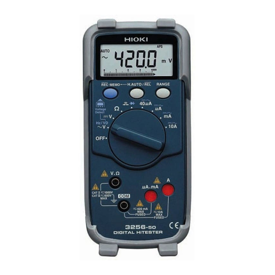
Page 14: Parts Names And Functions
1.3 Parts Names and Functions 1.3 Parts Names and Functions *: for details, see the following pages LCD display * REC•MEMO H.AUTO/REL Button Button * (Press this button to change to the function indicat- RANGE ed in blue.) Button * For other func- tions, see the fol- lowing pages. - Page 15 1.3 Parts Names and Functions LCD(Display) Indicates Recording function Indicates HOLD AUTO/ HOLD function Indicates Continuity Check function Indicates Relative function Indicates Diode Check function Indicates Autoranging Indicates Auto Power function Save is enabled Frequency units Indicates DC voltage/cur- Resistance and continuity check rent function units...
-
Page 16: Quick Reference
1.3 Parts Names and Functions Function Selector Press REC•MEMO when the function in parentheses is being (Diode Check function) used. Continuity function μ A DC/AC current Resistance function function μ A DC/AC current DC voltage function function (Voltage detecting) mA DC/AC current (Frequency function function) - Page 17 1.3 Parts Names and Functions Frequency Measure- MEMO RANGE • ( 1 - 4 ) ment "Hz" lights up Voltage MEMO × Bring test leads RANGE • detecting ( 1 - 4 ) close to the power "1" lights up line.
- Page 18 1.3 Parts Names and Functions Cancel the Auto-Power Save function. (Auto-Power Save function) V/Hz/ Press this button until a REC•MEMO beeping sound is generated. VD/Ω/ 40μA/μA/mA/ Enable the Power Save function: ("APS" Power Function Save lights up) change After mode 10 minutes Check the maximum, minimum, and average values during measurement.
-
Page 19: Chapter 2 Measurement Procedures
1.3 Parts Names and Functions Measurement Chapter 2 Procedures Observe the following precautions to avoid electric shock. • Always verify the appropriate setting of the function selector before connecting the test leads. • Disconnect the test leads from the mea- surement object before switching the func- tion selector. -
Page 20: Voltage Measurement
2.1 Voltage Measurement 2.1 Voltage Measurement • The maximum input voltage is 1000 VDC, 1000 Vrms, or 10 V•Hz. However, for CATIII circuits, the maximum voltage is 600 Vrms. Attempting to mea- sure voltage in excess of the maximum input could destroy the product and result in personal injury or death. - Page 21 2.1 Voltage Measurement AC Voltage Measurement Connect the test leads to the measurement object, and read the indicated value. Black DC Voltage Measurement Black Selecting the manual Press RANGE range: ("AUTO" is turned off) Reselecting the auto Press RANGE (for at least 1 sec- range: ond) ("AUTO"...
-
Page 22: Frequency Measurement
2.2 Frequency Measurement 2.2 Frequency Measurement • The maximum input voltage is 1000 VDC, 1000 Vrms, or 10 V•Hz. However, for CATIII circuits, the maximum voltage is 600 Vrms. Attempting to mea- sure voltage in excess of the maximum input could destroy the product and result in personal injury or death. -
Page 23: Current Measurement
2.3 Current Measurement 2.3 Current Measurement • Never apply voltage to the test leads when current measurement function selected. Doing so may damage the prod- uct and result in personal injury. • To avoid electrical accidents, remove power from the circuit before connecting the test leads. - Page 24 2.3 Current Measurement 40μA Measurement (42μA range) Move the function selector to the 40μA position. REC•MEMO Select DC ( ) or AC ( ) using REC•MEMO button. Connect the red test lead to ter- minal μA.mA, and the black test lead to terminal COM.
- Page 25 2.3 Current Measurement mA Measurement (40 mA/400 mA) Move the function selector to the position. Select DC ( ) or AC ( ) using REC•MEMO REC•MEMO button. Connect the red test lead to ter- minal μA.mA, and the black test lead to terminal COM.
-
Page 26: Resistance Measurement
2.4 Resistance Measurement 2.4 Resistance Measurement • Never apply voltage to test leads when the Resistance function is selected. Doing so may damage the product and result in personal injury. • To avoid electrical accidents, remove power from the circuit before measuring. Move the function selector to the Ω... -
Page 27: Continuity Check
2.5 Continuity Check 2.5 Continuity Check • Never apply voltage to test leads when the Continuity function is selected. Doing so may damage the product and result in personal injury. • To avoid electrical accidents, remove power from the circuit before measuring. Move the function selector to the position. -
Page 28: Diode Check
2.6 Diode Check 2.6 Diode Check • Never apply voltage to test leads when the Diode Check function is selected. Doing so may damage the product and result in personal injury. • To avoid electrical accidents, remove power from the circuit before measuring. Move the function selector to the position. -
Page 29: Chapter 3 Additional Functions
3.1 HOLD AUTO Function Additional Chapter 3 Functions 3.1 HOLD AUTO Function Functions V/Ω/40μA/μA/mA/10A Description Simply moving the test leads away from the mea- surement object holds the measured value. This function is useful when it is difficult to read the displayed value in the current location or both hands are being used to conduct the measure- ment. -
Page 30: Hold Function
3.2 HOLD Function 3.2 HOLD Function Functions V/Hz/Ω/ /40μA/μA/mA/10A Description This function holds the currently measured value. Turn on the power while pressing H.AUTO/REL button, and hold H.AUTO/REL the button down until a beeping Measure sound is generated (toggle the function selector to the desired Displayed position). -
Page 31: Overflow Warning Function
3.3 Overflow Warning Function 3.3 Overflow Warning Function Functions V/40μA/μA/mA/10A Description When the measured value exceeds the maxi- mum indication (4200 counts), O.F is displayed and an intermittent sound is generated. When the measured value exceeds 1050 counts in the ranges specified below, O.F is displayed and an intermittent sound is generated. -
Page 32: Relative Display Function
3.4 Relative Display Function 3.4 Relative Display Function Functions V/Ω/40μA/μA/mA/10A Description Once an arbitrary value is specified as a refer- ence, the relative value against the reference is displayed. This function is useful to check any discrepancy from the reference. Checking any discrepancy from the reference (when 10 V is defined as the reference in the voltage measurement) Measure a voltage of 10 V... - Page 33 3.4 Relative Display Function Application: Using the Relative Display function for the purpose of zero adjustment in the measurement of low resistances Short-circuit the test leads Move the function selector Ω to the position and con- nect the test leads to the equipment.
-
Page 34: Auto Power Save Function
3.5 Auto Power Save Function 3.5 Auto Power Save Function Functions All functions Description Approximately 10 minutes after completing final operation, the measurement product automati- cally enters Power Save mode. When the mea- surement product is turned on, it automatically enters Auto Power Save mode ("APS"... -
Page 35: Voltage Detecting Function
3.6 Voltage Detecting Function 3.6 Voltage Detecting Function This function should be used for the covered power line. Depending on the measurement sta- tus, the power may not be detected. Before using this function, check that the measuring device can detect the existing live power line. -
Page 36: Dynamic Recording Function
3.7 Dynamic Recording Function 3.7 Dynamic Recording Function Functions V/Ω/40μA/μA/mA/10A Description This function allows the maximum (MAX), mini- mum (MIN), average (AVG), and currently mea- sured values to be displayed selectively. It is useful for measuring any discrepancy over an extended period. -
Page 37: Memory Function
3.8 Memory Function 3.8 Memory Function Saving data to memory Functions V/Ω/40μA/μA/mA/10A Description This function memorizes the measured value held using the Hold Auto or Hold function. Hold the measured value using the Hold Auto or Hold function. Press the REC•MEMO button REC•MEMO... - Page 38 3.8 Memory Function Calling data from memory Call data from memory as specified below. RANGE Turn on the power while pressing the RANGE button. Move the function selector to position ( hold the but- ton down until a beeping sound is generated).
-
Page 39: Chapter 4 Specifications
4.1 General Specifications Chapter 4 Specifications 4.1 General Specifications Measurement Dual integration Method AC Measurement Average rectifying measurement System Function DC voltage ( V), AC voltage( Ω Resistance ( ), DC current ( AC current ( A), Continuity check( Diode check( ), Frequency (Hz), Voltage detecting Additional... - Page 40 4.1 General Specifications V.Ω terminal (V, Hz, Ω, continuity, diode) Input Terminals μA.mA/ A/ COM terminals Equipped with terminal shutter to prevent improper operation. Function Selector Rotary selector Range Switching Auto/Manual Range Sampling Rate 2.5 S/s (except Frequency), 5 S/s (Fre- quency), 25 S/s (Update of bar graph) Power Supply Two manganese (R03) batteries or...
- Page 41 (2.99"W × 6.57"H × 1.30"D) (without protrusions) Approx. 260 g (9.2 oz) Accessories 9207-10 TEST LEAD Instruction Manual Two R03 manganese batteries Protective holster(3256-51) or 9378 CARRYING CASE (3256-50) Applicable Safety EN61010-1:2001 Standards EN61010-031:2002 Pollution Degree 2 Measurement Category III(600 V), Measurement CategoryII(1000 V)
- Page 42 4.1 General Specifications Protective Fuse 10A terminal: TDC600-10A (made by Cooper Bussmann*) Rating 10 A/600 VAC Fast-Acting Breaking capacity: 10 kA/250 VAC, 200 A/600 VAC μAmA terminal:70125 (made by SIBA Inc.) Rating 0.5 A/700 VAC Fast-Acting Breaking capacity: 50 kA *Cooper Industries Inc., Bussmann Division,...
-
Page 43: Accuracy
4.2 Accuracy 4.2 Accuracy Accuracy guarantee for 23±5°C(73±9°F), 80%RH or less temperature and hu- midity Guaranteed accuracy 1 year period Regulated power sup- 3.4 V or lower (until the mark ply range lights up) (rdg.: displayed value, dgt.: resolution) Voltage Measurement Range Accuracy Input Impedance... - Page 44 4.2 Accuracy (rdg.: displayed value, dgt.: resolution) Frequency Measurement Range Accuracy Input level (Range) [Hz] ±(rdg.)±(dgt.) 199.99 ±0.02%±2 1: 0.8 to 4 V (4.200V) 1999.9 ±0.02%±1 2: 4 to 40 V (42.00V) 19.999k ±0.02%±1 3: 40 to 400 V (420.0V) 199.99k ±0.02%±1 4: 400 to 1000 V (1000V)
- Page 45 4.2 Accuracy (rdg.: displayed value, dgt.: resolution) Current Measurement Range Accuracy Input Impedance ±(rdg.)±(dgt.) (Shunt resistance) 42.00μ ±1.5%±4 10kΩ Approx. 420.0μ ±1.5%±4 100Ω Approx. 4200μ ±1.5%±4 100Ω Approx. 42.00m ±1.5%±4 1Ω Approx. 420.0m ±1.5%±4 1Ω Approx. 10.00*2 ±1.5%±4 0.01Ω Approx. 42.00μ...
- Page 46 4.2 Accuracy...
-
Page 47: Chapter 5 Maintenace And Service
5.1 Replacing the Batteries and Fuses Maintenace and Chapter 5 Service 5.1 Replacing the Batteries and Fuses • To avoid electric shock when replacing the batteries and fuses, first disconnect the test leads from the object to be mea- sured. •... - Page 48 5.1 Replacing the Batteries and Fuses μA.mA A fuse is mounted to the terminals in order to protect the circuit. If the current cannot be measured, the fuse may have blown due to overcurrent. Replace the fuse or battery in accordance with the procedure specified below.
-
Page 49: Cleaning
• If the product seems to be malfunctioning, con- firm that the batteries are not discharged, and that the test leads and fuse are not open cir- cuited before contacting your dealer or Hioki rep- resentative. • To avoid corrosion from battery leakage, remove the batteries from the product if it is to be stored for a long time. - Page 50 5.3 Service...
- Page 53 HIOKI 3256-50/51 DIGITAL HiTESTER Instruction Manual Publication date: September 2006 Revised edition 4 Edited and published by HIOKI E.E. CORPORATION Technical Support Section All inquiries to International Sales and Marketing De- partment 81 Koizumi, Ueda, Nagano, 386-1192, Japan TEL: +81-268-28-0562 / FAX: +81-268-28-0568 E-mail: os-com@hioki.co.jp...
- Page 54 HEAD OFFICE 81 Koizumi, Ueda, Nagano 386-1192, Japan TEL +81-268-28-0562 / FAX +81-268-28-0568 E-mail: os-com@hioki.co.jp URL http://www.hioki.co.jp/ HIOKI USA CORPORATION 6 Corporate Drive, Cranbury, NJ 08512, USA TEL +1-609-409-9109 / FAX +1-609-409-9108 3256C981-04 06-09H Printed on recycled paper...
Need help?
Do you have a question about the 3256-50 and is the answer not in the manual?
Questions and answers