
Subscribe to Our Youtube Channel
Related Manuals for Hioki DT4251


Summary of Contents for Hioki DT4251
-
Page 1: Digital Multimeter
Instruction Manual DT4251 DT4252 DT4253 DIGITAL MULTIMETER June 2014 Revised edition 1 DT4251A981-01 14-06H... -
Page 3: Table Of Contents
Attaching the strap ............ 31 Using the Carrying Case ......33 Performing Measurements Inspection Before Use ........37 Measuring Voltage.........42 Measuring AC voltage ..........42 Measuring DC voltage ..........43 Measurement using the AC and DC automatic judgment (DT4251 DT4253) ........43 Measuring Frequencies ........44... - Page 4 Measuring Current (DT4252 DT4253) ..51 Measuring DC/AC ............. 51 3.10 Measuring AC Using Clamp-on Probe (DT4251 DT4253) ..........54 3.11 Checking the Electric Charge (DT4251) ..56 Using Instrument Conveniently Selecting the Measurement Range ....57 Measuring with the auto range ......... 57 Measuring with the manual range ......
- Page 5 Specifi cations General Specifi cations .........73 Electrical Characteristics ......75 Accuracy Table ..........77 Maintenance and Service Repair Inspection and Cleaning ....87 Troubleshooting ..........88 Error Display ..........91 Replacing Fuses ..........92 Appendix Appx.1 Appx. 1 RMS and Average ......Appx.1...
-
Page 7: Introduction
Introduction Introduction Thank you for purchasing the HIOKI DT4251, DT4252, DT4253 Digital Multimeter. To obtain maximum performance from the product, please read this manual fi rst, and keep it handy for future reference. Verifying Package Contents When you receive the instrument, inspect it carefully to ensure that no damage occurred during shipping. -
Page 8: Options (Sold Separately)
Options (sold separately) Options (sold separately) The following options are available for the instrument. Contact your authorized Hioki distributor or reseller when ordering. Connecting cables *1: CATIV 600 V/CATIII 1000 V/CATII 1000 V *2: CATIV 600 V/CATIII 1000 V *3: CATIII 1000 V... -
Page 9: Carrying Case
Options (sold separately) For the clamp current measurement (Compatible only with the DT4251 and DT4253) 9010-50, 9018-50, 9132-50 Clamp-on Probe 9704 Conversion Adapter Clamp-on probe Rated current Diameter of the measurable conductor 46 mm or less 9010-50, 9018-50 500 Arms ... - Page 10 Options (sold separately) Z5004 Magnetic Strap (p. 31) Attach this strap to the instrument and secure it on the wall surface such as a metal plate for use. DT4900-01 Communication Package (USB) (p. 68) A communication adapter, USB cable, PC software, and communication specifi...
-
Page 11: Safety Notes
Safety Notes Safety Notes This instrument is designed to conform to IEC 61010 Safety Standards, and has been thoroughly tested for safety prior to shipment. However, using the instrument in a way not described in this manual may negate the provided safety features. Before using the instrument, be certain to carefully read the following safety notes. - Page 12 Safety Notes Notation In this manual, the risk seriousness and the hazard levels are classifi ed as follows. Indicates an imminently hazardous situation that will DANGER result in death or serious injury to the operator. Indicates a potentially hazardous situation that may WARNING result in death or serious injury to the operator.
- Page 13 Safety Notes Symbols affi xed to the instrument Indicates cautions and hazards. When the symbol is printed on the instrument, refer to a corresponding topic in the Instruction Manual. Indicates that dangerous voltage may be present at this terminal. Indicates a double-insulated device. Indicates a fuse.
- Page 14 Safety Notes Screen display This instrument uses the following screen displays. A B C D E F G H I J K L M N O P Q R S T U V W X Y Z 1 2 3 4 5 6 7 8 9 0 A different display is used in the case below.
- Page 15 Safety Notes Measurement categories To ensure safe operation of measuring instruments, IEC 61010 establishes safety standards for various electrical environments, categorized as CAT II to CAT IV, and called measurement categories. DANGER • Using a measuring instrument in an environment designated with a higher-numbered category than that for which the instrument is rated could result in a severe accident, and must be carefully avoided.
-
Page 16: Usage Notes
• Before using the instrument the fi rst time, verify that it operates normally to ensure that no damage occurred during storage or shipping. If you fi nd any damage, contact your authorized Hioki distributor or reseller. Installation Installing the instrument in inappropriate locations may cause a malfunction of instrument or may give rise to an accident. - Page 17 Usage Notes Handling the cables WARNING To prevent electric shock, when measuring the voltage of a power line use a test lead that satisfi es the following criteria: • Conforms to safety standards IEC61010 or EN61010 • Of measurement category III or IV •...
- Page 18 • When the clamp-on probe is opened, do not allow the metal part of the clamp to touch any exposed metal, or to short between 2 lines, and do not use over bare conductors. (For the clamp current measurement, only the DT4251 and DT4253)
- Page 19 Precautions during shipment Observe the following during shipment. Hioki cannot be responsible for damage that occurs during shipment. CAUTION • During shipment of the instrument, handle it carefully so that it is not damaged due to a vibration or shock.
- Page 20 Usage Notes...
-
Page 21: Overview
Overview 1.1 Overview and Features This measuring instrument is a multi-function digital multimeter that ensures both safety and durability. Main features and functions • Speedy display of the RMS • Solid body which can be used for an measured value extended period of time (drop-proof) •... -
Page 22: Parts Names And Functions
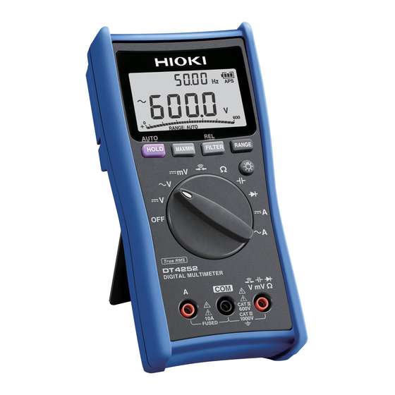
Parts Names and Functions 1.2 Parts Names and Functions Front Some indications are different among the DT4251, DT4252, and DT4253. Display (p. 22) Operation keys (p. 17) Rotary DT4252 switch (p. 18) Measurement terminals (p. 20) DT4251 DT4253... - Page 23 Parts Names and Functions Operation keys Pressed down for Power-on Normal at least 1 second option (p. 70) Cancels the Manually sets/ Sets/cancels the auto cancels the hold hold function for the auto power save function for the displayed value. function (APS).
- Page 24 Parts Names and Functions Rotary switches and measurement descriptions DT4251 DT4252 DT4253 Function DT4251 DT4252 DT4253 AC voltage and frequency √ √ √ measurement √ √* √ DC voltage measurement DC voltage measurement √ (High accuracy 600.0 mV range) DC/AC voltage measurement √...
- Page 25 Parts Names and Functions Function DT4251 DT4252 DT4253 √ √ √ Continuity check √ √ √ Resistance measurement √ √ √ Electrostatic capacity √ √ √ Diode test AC measurement √ √ (Clamp sensor used) √ Electrical charge measurement √...
- Page 26 Parts Names and Functions Measurement terminals DT4251 DT4252 DT4253 Current measurement terminal. Hereafter referred to as “A terminal (μA terminal, mA terminal)”. The red test lead is connected. Commonly used for each measurement. Hereafter referred to as “COM terminal”. The black test lead is connected.
- Page 27 Parts Names and Functions Rear Communication port When the communication adapter supplied with the optional DT4900- 01 Communication Package is connected, the data can be transmitted to the PC. (p. 68) Test lead holder The test lead can be held. Strap hole The optional Z5004 Magnetic Strap can be attached.
-
Page 28: Display
(p. 61) temperature is displayed. AC, DC Indication (example): In the case of *1: DT4251 30 V input in the 60 V range, the bar *2: DT4252 is displayed to the center of the scale. *3: DT4253... -
Page 29: Alarm Display And Battery Indicator
Alarm Display and Battery Indicator 1.4 Alarm Display and Battery Indicator When the measured value exceeds the maximum input range in each range Voltage/Current measurement The measured value and OVER blink and the red LED lights up. Measurement other than voltage and current The measured value and OVER blink. - Page 30 Alarm Display and Battery Indicator Power shutdown When the charge is 0% (less than 4.0 V ± 0.1 V), “bAtt” appears in the display for 3 seconds and the power is shut down.
-
Page 31: Preparation For Measurements
Preparation for Measurements 2.1 Measurement Workfl ow Before using the instrument, be sure to read “Usage Notes” (p. 10). Installation and connection Insert the batteries. (p. 26) As necessary, have other optional items available and ready. Perform the startup check. (p. 37) Measurement Turn on the power and select the measurement function. -
Page 32: Inserting/Replacing Batteries
Inserting/Replacing Batteries 2.2 Inserting/Replacing Batteries Before using the instrument fi rst time, insert 4 LR03 alkaline batteries. Before measurements, check that the battery level is suffi cient. When the battery charge is low, replace the batteries. Nickel-metal hydride batteries Nickel-metal hydride batteries can be used. However, the discharge characteristic of these batteries is different from that of alkaline batteries. - Page 33 Inserting/Replacing Batteries • The indicator appears when the battery charge diminishes. Replace the batteries as soon as possible. The power may be turned off when the backlight lights up or a buzzer sounds. • After use, be sure to turn off the instrument. •...
-
Page 34: Using Test Leads
Using Test Leads 2.3 Using Test Leads The L9207-10 Test Leads supplied with the instrument are used for measurements. Depending on measurement locations, use our optional measurement cables. For details on the optional items, see “Options (sold separately)” (p. 2). WARNING •... - Page 35 Using Test Leads L9207-10 Test Lead Sleeves Barriers Black Plugs Metal pins Cables The plugs of the test leads are covered with the safety caps. Before use, remove the caps. Safety cap Metal pin Connect to the object to be measured. 4 mm or less (sleeve attached) 19 mm or less (sleeve removed) Diameter ...
- Page 36 Using Test Leads Removing and attaching the sleeves Removing the sleeves Attaching the sleeves Gently hold the bottom of the Insert the metal pins of the test sleeves and pull the sleeves off. leads into the holes of the sleeves, Safely store the removed sleeves and fi...
-
Page 37: Installation In Measurement Location
Installation in Measurement Location 2.4 Installation in Measurement Location Using the instrument with the stand Position the instrument with the stand at the rear. CAUTION • Do not position the instrument on an unstable table or inclined surface. • When the instrument is set on the stand, do not apply a strong force above. - Page 38 Installation in Measurement Location DANGER Those with medical electronics such as pacemakers should not use the Z5004 Magnetic Strap. Nor should such persons approach the Z5004. It is extremely dangerous. The electronics may not operate properly and the life of the operator may be put at great risk. CAUTION •...
-
Page 39: Using The Carrying Case
Using the Carrying Case 2.5 Using the Carrying Case C0201 Carrying Case The test leads can be stored. The instrument can be stored. The instruction manual can be stored at the bottom of the case. - Page 40 Using the Carrying Case Removing the cover Unfasten the button on the side of the cover marked with OPEN. Flip the cover to the back. Fasten the button.
- Page 41 Using the Carrying Case Using the instrument with a strap around the neck 1 1 1 Unfasten the button. Secure the button at the position shown in the fi gure.
- Page 42 Using the Carrying Case...
-
Page 43: Performing Measurements
Before using the instrument the fi rst time, verify that it operates normally to ensure that no damage occurred during storage or shipping. If you fi nd any damage, contact your authorized Hioki distributor or reseller. Appearance check of the instrument and test leads... -
Page 44: Operation Check
Inspection Before Use Check item Action No indicators are missing. Display all indicators and ensure that no indicators are missing. (p. 71) If any of the indicators are missing, send the instrument for repair. Operation check This section introduces some of the operation checks. Periodical calibration is necessary in order to ensure that this instrument operates according to its specifi... - Page 45 Inspection Before Use Measure samples (such as battery, commercial power supply, and resistor) of which values have already been known, and check that the appropriate values appear. Check method Action Example: Normal: Perform the AC voltage An already-known value appears. measurement to measure the (In this example, the commercial commercial power supply, and then...
- Page 46 Inspection Before Use Check that the fuse is not broken. DT4252 check method Action 1. Set the rotary switch to Normal: resistance measurement. Fuse rating Resistance 2. Connect the tip of the red test lead to the A terminal and check Ω...
- Page 47 Inspection Before Use Check that the electrical charge detection function operates normally. (Only the DT4251) Check method Action Position the detector on a known Normal: power supply, such as a power outlet. A buzzer sounds and the red LED lights up (energized).
-
Page 48: Measuring Voltage
3.2 Measuring Voltage AC/DC voltage measurement and measurement using the AC and DC automatic judgment (only the DT4251 and DT4253) can be performed. Furthermore, the maximum, minimum, and average values of the measured values can be checked. (p. 6 3) -
Page 49: Measuring Dc Voltage
Black Measurement using the AC and DC automatic judgment (DT4251, DT4253) The AC and DC are automatically judged and the voltage is measured. (The instrument does not measure both AC and DC at the same time) voltage... -
Page 50: Measuring Frequencies
Measuring Frequencies 3.3 Measuring Frequencies During voltage/current measurement of AC, the frequency can be checked in the sub display. The frequency display is autoranging. The AC voltage and current ranges can be changed by pressing the RANGE key. Frequency • If signals out of the range of frequency measurement are measured, “-----” appears. -
Page 51: Checking Continuity
Checking Continuity 3.4 Checking Continuity The input short circuit is detected and informed via a buzzer and red LED. WARNING Before measuring, be sure to turn off the power to the measurement circuit. Otherwise, electric shock may occur or the instrument may be damaged. Black Detection Threshold... -
Page 52: Measuring Diode
Measuring Diode 3.5 Measuring Diode The forward voltage of the diode is measured. If the forward voltage is within the range from 0.15 V to 1.5 V, it is indicated via a buzzer (intermittent buzzer sound) and red LED. WARNING Before measuring, be sure to turn off the power to the measurement circuit. -
Page 53: Measuring Resistance
Measuring Resistance 3.6 Measuring Resistance Resistance is measured. To measure the low resistance accurately, it is necessary to cancel the resistance of the test leads. Perform zero adjustment for the displayed value using the relative value display (relative function) in advance. -
Page 54: Measuring Temperatures (Dt4253)
Measuring Temperatures (DT4253) 3.7 Measuring Temperatures (DT4253) Using our optional DT4910 Thermocouples (K), temperatures can be measured. CAUTION To avoid damage to the instrument, do not input any voltage or supply current to the thermocouple. When a breaking state of the Thermocouples (K) is detected Checking the temperature change... - Page 55 Measuring Temperatures (DT4253) When measuring temperatures with the thermocouple applied to the surface of the measurement object Clean the surface so that the thermocouple can make contact with the object securely. If no numeric value is displayed after the thermocouple is attached ([OPEn] is displayed): The instrument or thermocouple may be malfunctioning.
-
Page 56: Measuring Electrostatic Capacities
Measuring Electrostatic Capacities 3.8 Measuring Electrostatic Capacities The capacity of the capacitor is measured. WARNING Before measuring, be sure to turn off the power to the measurement circuit. Otherwise, electric shock may occur or the instrument may be damaged. Do not measure the capacitor which has been charged. -
Page 57: Measuring Current (Dt4252, Dt4253)
Measuring Current (DT4252, DT4253) 3.9 Measuring Current (DT4252, DT4253) DC/AC is measured. DANGER • Do not input any voltage to the current measurement terminals. Doing so may result in short circuit accidents. • To avoid electrical accidents, turn off the power to the circuit before measuring and then connect the test leads. - Page 58 Measuring Current (DT4252, DT4253) DT4253 Control board Black Example: Measuring the current of the burner fl ame (μA) The measured current value of the burner fl ame varies with the input impedance of the instrument. Ω The μA input impedance of this instrument is approx. 1k DT4252 Load Power...
- Page 59 Measuring Current (DT4252, DT4253) 4 - 20 mA % conversion (DT4253) The 4 - 20 mA signal of the instrumentation system can be converted to 0% to 100% and checked. 4 mA - 20 mA → 0% - 100% (An input less than 4 mA or exceeding 20 mA is displayed with [----].) Two-wire 4-20 mA transmitter...
-
Page 60: Measuring Ac Using Clamp-On Probe (Dt4251, Dt4253)
Measuring AC Using Clamp-on Probe (DT4251, DT4253) 3.10 Measuring AC Using Clamp-on Probe (DT4251, DT4253) The current is measured using our optional clamp-on probe (9010- 50, 9018-50, 9132-50). To connect to this instrument, the 9704 Conversion Adapter is required. Before using the clamp-on probe, be sure to read the Instruction Manual which accompanies the optional clamp. - Page 61 Measuring AC Using Clamp-on Probe (DT4251, DT4253) When clamping a cable Attach the clamp around only one conductor. Single-phase (2-wire) or three-phase (3-wire) cables clamped together will not produce any reading. When the measured value and OVER blink The measured value exceeds the maximum display counts.
-
Page 62: Checking The Electric Charge (Dt4251)
Checking the Electric Charge (DT4251) 3.11 Checking the Electric Charge (DT4251) Whether a power line is energized can be checked easily. If the power line is energized, it is indicated via a buzzer and display. Use this function for coated power lines. The detection may not be made depending on the measurement conditions. -
Page 63: Using Instrument Conveniently
Using Instrument Conveniently 4.1 Selecting the Measurement Range Auto or Manual range can be selected. In the case of measurement where the desired range can be selected, [RANGE:] lights up at the bottom of the display. • Auto range Sets the optimum range automatically in accordance with the actual measurement. -
Page 64: Retaining The Measured Value
Retaining the Measured Value 4.2 Retaining the Measured Value The measured value is retained manually or automatically. (The bar graph is updated.) • Manually When HOLD is pressed, the measured value is retained. (HOLD lights up.) • Automatically When HOLD is pressed and held for at least 1 second, auto mode starts. - Page 65 Retaining the Measured Value Conditions for auto holding Stable range for auto Threshold for auto holding holding Function (Display count) (Dead zone display count) AC voltage 120 or less (except 1000 V 120 or less (except 1000 V range) range) 20 or less (1000 V range) 20 or less (1000 V range) DC voltage...
- Page 66 Retaining the Measured Value Conceptual diagram (AC voltage) Displayed value Auto hold Not retained automatically. (Example) 100.0 V (The threshold is not exceeded.) Auto hold (Example) 99.0 V Threshold for Stable range auto holding Measured value Dead zone Connect to the Release Connect Release...
-
Page 67: Reducing The Noise (Filter)
Reducing the Noise (FILTER) 4.3 Reducing the Noise (FILTER) WARNING To avoid electric shock or other personal injury, select the appropriate passband setting when measuring the AC voltage. If an inappropriate frequency is selected, the measured value displayed will not be correct. The infl... - Page 68 Reducing the Noise (FILTER) Example of frequency property when a fi lter is used Measured (AC voltage 600.0 V range, 100 V input) value [V] Filter OFF Passband 500 [Hz] Passband 100 [Hz] 1000 10000 Frequency at 100 V input (Hz) Example: Power frequency on an aircraft or marine vessel is 400 Hz When voltage is 100 V FILTER setting...
-
Page 69: Checking The Maximum/Minimum/Average
Checking the Maximum/Minimum/Average 4.4 Checking the Maximum/Minimum/ Average The maximum value (MAX), minimum value (MIN), and average value (AVG) after the start of measurement can be checked. When the following measurement function is selected, this function is disabled. AUTO V, Electric charge measurement Press Each time the key is pressed, the main display is changed. -
Page 70: Checking The Relative Value/Performing Zero Adjustment
Checking the Relative Value/Performing Zero Adjustment 4.5 Checking the Relative Value/ Performing Zero Adjustment The relative value comparing to the standard value can be checked (relative function). It can also be used as the zero adjustment function. Zero adjustment eliminates the infl uences of the test lead wiring resistance (continuity, resistance measurement) and the wiring capacity (capacitor measurement). - Page 71 Checking the Relative Value/Performing Zero Adjustment Example 2: Temperature measurement When the standard value is measured, press for at least 1 second. The standard temperature is fi xed as T1. ( △ T and T1 light up.) The currently measured temperature is displayed as T2 alternately with T1.
-
Page 72: Performing Zero Adjustment
Checking the Relative Value/Performing Zero Adjustment Performing zero adjustment When performing zero adjustment, the condition of the test leads varies depending on the measurement function. Perform zero adjustment, referring to the table below. Ω Measurement function V, A, Condition of the test leads Short circuit Open Example 1: Resistance measurement... -
Page 73: Turning On The Backlight
Turning On the Backlight 4.6 Turning On the Backlight The backlight can be turned on/off by pressing The backlight automatically turns off if the instrument is not operated for approx. 40 seconds. The automatic backlight deactivation function can be disabled. (p. -
Page 74: Communicating With Pc
Communicating with PC 4.8 Communicating with PC Using the optional DT4900-01 Communication Package, it is possible to transmit data to the PC or to control the instrument. Install the special software on the PC. (See the Instruction Manual which accompanies with the communication package.) Attaching the USB cable to the instrument (p. - Page 75 Communicating with PC Attaching the communication adapter to the instrument Attach the USB cable communication adapter. Connect the USB cable to the communication Communication adapter. adapter Communication port • Connect the cables, being careful to orient each cable correctly. • During communication, appears in the display.
-
Page 76: Power-On Option Table
Power-on Option Table 4.9 Power-on Option Table The settings in the instrument can be changed or checked. When the power is turned off, all settings except temperature display unit changes are lost. When the operation key is released after changing the setting, the regular display then reappears. - Page 77 Displaying all indicators (Second position from OFF) FACT: Indicates that the settings have been adjusted by Hioki. USER: Indicates that the settings have been adjusted Checking the by the user. adjustment source...
-
Page 78: Changing The Temperature Display Unit
Power-on Option Table Changing the temperature display unit The units of temperature (°C or °F) can be changed. Turn on the power while pressing simultaneously. Press and hold simultaneously. Press to change the (Display: tEMP) temperature unit. Press and hold to save the setting. -
Page 79: Specifi Cations
Specifi cations 5.1 General Specifi cations Power supply LR03 alkaline battery × 4 Battery • 5.5 V or more lights up. indicator • Less than 5.0 V to 5.5 V lights up. warning • Less than 4.5 V to 5.0 V lights up. - Page 80 General Specifi cations Digital multimeter ↔ DT4900-01 Communication Package (USB) ↔ PC communication After a command is sent from the PC, [ ] lights up and communication begins. After the command is sent from the PC, a response operation is performed. Accessories •...
-
Page 81: Electrical Characteristics
Electrical Characteristics 5.2 Electrical Characteristics Noise • DCV: -60 dB or more (50 Hz/60 Hz) suppression NMRR Ω Noise • DCV: -100 dB or more (DC/50 Hz/60 Hz, 1k suppression unbalance) Ω • ACV: -60 dB or more (DC/50 Hz/60 Hz, 1k CMRR unbalance) Response time... - Page 82 Power voltage 6.0 V, auto power save function activated Continuous LR03 alkaline batteries, backlight off: Approx. 130 hours operating time *1: DT4251 *2: DT4252 *3: DT4253 *4: Until the values stabilize within the accuracy specifi cation range. *5: Measured within the measurement range (excluding range movement).
-
Page 83: Accuracy Table
Accuracy Table 5.3 Accuracy Table Accuracy warranty period 1 year Regulated power supply range Until the power shutdown (4.0 V ± 0.1 V or more ) Accuracy guarantee for 23°C ± 5°C (73°F ± 9°F), 80%RH or less temperature and humidity (non-condensating) Temperature characteristic •... - Page 84 Accuracy Table Transient overvoltage: 8000 V • Crest factor: The crest factor is 3 up to 4000 counts and reduces linearly to 2 at 6000 counts. • Connection method: AC coupling • Auto range movement threshold: 6,000 counts or more for upper range 540 counts or less for lower range *1: The accuracy is specifi...
- Page 85 Accuracy Table Minimum sensitivity voltage/current (sine wave) AC voltage range AC range Measurement Range range 6.000 V 60.00 V 600.0 V 1000 V 6.000 A 10.00 A 99.99 5.00 Hz to 0.600 V 6.00 V 60.0 V 100 V 0.6 A 3.00 A 99.99 Hz or more...
- Page 86 Accuracy Table DC voltage (High accuracy 600.0 mV) Range Accuracy Input impedance Ω 600.0 mV ±0.2% rdg. ±5 dgt. 10.2 M ±1.5% • Overload protection: 1000 V DC/1000 V AC or 2 × 10 V • Hz (energized for 1 minute) AUTO V Accuracy Range...
- Page 87 Accuracy Table Continuity Measurement Range Accuracy Open circuit voltage current Ω 200 μA ±20% 600.0 ±0.7% rdg. ±5 dgt. 1.8 V DC or less • Overload protection: 1000 V DC/1000 V AC or 2 × 10 V • Hz (energized for 1 minute) Current under overload: Steady state 15 mA or less, transient state 0.8 A or less...
- Page 88 Accuracy Table Electrostatic capacity Range Accuracy Charging current 1.000 μF 10 n/100 n/1 μA ±20% ±1.9% rdg. ±5 dgt. 10.00 μF 100 n/1 μ/10 μA ±20% ±1.9% rdg. ±5 dgt. 100.0 μF 1 μ/10 μ/100 μA ±20% ±1.9% rdg. ±5 dgt. 10 μ/100 μ/200 μA ±20% 1.000 mF ±1.9% rdg.
- Page 89 Accuracy Table Temperature Thermocouple type Range Accuracy -40.0°C to 400.0°C ±0.5% rdg. ±2°C -40.0°F to 752.0°F ±0.5% rdg. ±3.6°F • Overload protection: 1000 V DC/1000 V AC or 2 × 10 V • Hz (energized for 1 minute) Current under overload: Steady state 15 mA or less, transient state 0.8 A or less •...
- Page 90 Accuracy Table *1: The accuracy is specifi ed in 1% or more of the range, however, ±5 dgt. should be added to 5% or less of the range. • Accuracy guarantee range for frequency: 40 Hz to 1 kHz (Measured values outside the accuracy guarantee range for frequency are also displayed.) The accuracy is not specifi...
- Page 91 Accuracy Table DC (A) Range Accuracy Input impedance Ω 6.000A ±0.9% rdg. ±5 dgt. ±30% Ω 10.00A ±0.9% rdg. ±5 dgt. ±30% • Overload protection: 11 A/1000 V fuse, breaking capacity 50 kA AC/30 kA • Auto range movement threshold: 6,000 counts or more for upper range 540 counts or less for lower range AC (A) Accuracy...
- Page 92 Accuracy Table Electric charge Detection voltage range Detection target frequency 80 V AC to 600 V AC 50/60 Hz • During voltage detection, a continuous buzzer sounds and the red LED lights up. *1: In contact with the insulated wire that is equivalent to IV2 mm...
-
Page 93: Maintenance And Service
Maintenance and Service 6.1 Repair, Inspection, and Cleaning DANGER Customers are not allowed to modify, disassemble, or repair the instrument. Doing so may cause fi re, electric shock, or injury. Calibrations IMPORTANT Periodic calibration is necessary in order to ensure that the instrument provides correct measurement results of the specifi... -
Page 94: Troubleshooting
• When a malfunction of the instrument is suspected, check the information in “Before sending the instrument for repair” and then, if necessary, contact your authorized Hioki distributor or reseller. • When sending the instrument for repair, remove the batteries and pack it carefully to prevent damage during transportation. - Page 95 Troubleshooting Symptom Check and/or remedy The measurement If the measured current value does not appear, value does not check that the fuse is not blown. appear. Check method: “Check that the fuse is not broken.” Even after the (p. 40) measurement, 0 If the fuse is blown, replace it with the specifi...
- Page 96 Using the relative value display function, zero zero adjustment. adjustment can be performed. (p. 66) Would like to replace The fuse can be purchased via authorized Hioki the fuse. distributor or reseller. Would like to know how to obtain the fuse.
-
Page 97: Error Display
Program When the error appears in the ROM error Err 002 display, it is necessary to repair Adjustment data the instrument. EEPROM error Contact your authorized Hioki Err 004 Memory data distributor or reseller. ADC error Err 005 Hardware malfunction... -
Page 98: Replacing Fuses
Size: 10.3 mm × 38 mm (DT4252) 1000 V The fuses can be purchased via authorized Hioki distributor or reseller. When removing the fuse, do not apply excessive force on the fuse holder. If the fuse holder is deformed, the connection becomes... - Page 99 Replacing Fuses CAUTION When replacing the fuse, do not allow foreign matter to enter the instrument. It may cause a malfunction. Do not remove the fuse using the tip of test lead L9207-10 supplied with the instrument. The tip of the test lead may bend.
- Page 100 Replacing Fuses...
-
Page 101: Appendix
Appendix Appx. 1 RMS and Average Difference between the RMS and Average When converting AC to RMS, 2 methods are available, “True RMS method (True RMS indication)” and “Average method (Average rectifying RMS indication)”. In the case of the sine wave where no skew is included, the same values are indicated in both methods. - Page 102 RMS and Average Appx.
- Page 103 13-09...
Need help?
Do you have a question about the DT4251 and is the answer not in the manual?
Questions and answers